

Crestron DM-NVX-E30, DM-NVX-D30, DM-NVX-E30C, DM-NVX-D30C Product Manual

DM NVX™ Network AV
Encoders/Decoders
DM-NVX-E30
DM-NVX-D30
DM-NVX-E30C
DM-NVX-D30C
Product Manual
Crestron Electronics, Inc.

Original Instructions
The U.S. English version of this document is the original instructions.
All other languages are a translation of the original instructions.
The product warranty can be found at www.crestron.com/legal/sales-terms-conditions-warranties.
The specific patents that cover Crestron products are listed at www.crestron.com/legal/patents.
Certain Crestron products contain open source software. For specific information, visit
www.crestron.com/legal/open-source-software.
Crestron, the Crestron logo, 3-Series, Crestron Toolbox, Crestron XiO Cloud, DigitalMedia, DM NVX, and DM NVX Director
are either trademarks or registered trademarks of Crestron Electronics, Inc. in the United States and/or other countries.
Dolby and Dolby Atmos are either trademarks or registered trademarks of Dolby Laboratories in the United States and/or
other countries. DTS HD and DTS:X are either trademarks or registered trademarks of DTS, Inc. in the United States and/or
other countries. HDMI and the HDMI logo are either trademarks or registered trademarks of HDMI Licensing LLC in the
United States and/or other countries. Active Directory is either a trademark or registered trademark of Microsoft
Corporation in the United States and/or other countries. DisplayPort is either a trademark or registered trademark of Video
Electronics Standards Association in the United States and/or other countries. Other trademarks, registered trademarks,
and trade names may be used in this document to refer to either the entities claiming the marks and names or their
products. Crestron disclaims any proprietary interest in the marks and names of others. Crestron is not responsible for errors
in typography or photography.
©2019 Crestron Electronics, Inc.

Contents
Introduction ................................................................................................................................... 1
Physical Description .................................................................................................................... 2
DM-NVX-E30 and DM-NVX-D30 ........................................................................................................... 2
Front Panel, DM-NVX-E30 ................................................................................................................ 2
Front Panel, DM-NVX-D30 ............................................................................................................... 3
Rear Panel, DM-NVX-E30 and DM-NVX-D30 ............................................................................... 4
DM-NVX-E30C ........................................................................................................................................... 5
DM-NVX-D30C ........................................................................................................................................... 6
Configuration and Status .......................................................................................................... 7
DMF-CI-8 Chassis Details ........................................................................................................................ 7
Using the Web Interface .................................................................................................................... 7
Using SIMPL Windows ....................................................................................................................... 8
DM NVX Director Virtual Switching Appliance .................................................................................... 8
Stream Statistics ....................................................................................................................................... 9
Using the Web Interface .................................................................................................................... 9
Using SIMPL Windows ..................................................................................................................... 10
Multicast TTL (Time-to-Live) ................................................................................................................. 10
Using the Web Interface .................................................................................................................. 10
Using SIMPL Windows ...................................................................................................................... 11
DSCP (Differentiated Services Code Point) ...................................................................................... 12
EDID (Extended Display Identification Data) .................................................................................... 13
Subscriptions ............................................................................................................................................ 14
Using the Web Interface .................................................................................................................. 14
Using SIMPL Windows ..................................................................................................................... 15
7.1 Surround Sound Audio ...................................................................................................................... 15
Analog Audio Output .............................................................................................................................. 16
Using the Web Interface .................................................................................................................. 16
Using SIMPL Windows ..................................................................................................................... 16
Crestron XiO Cloud Service Connection ............................................................................................. 17
Enterprise-Grade Security ..................................................................................................................... 18
IEEE 802.1X Authentication ............................................................................................................ 18
Authentication Management ......................................................................................................... 19
Fan Control .............................................................................................................................................. 20
Using the Web Interface ................................................................................................................. 20
Using SIMPL Windows .................................................................................................................... 20
Automatic Firmware Update ................................................................................................................ 21
Product Manual – DOC. 8425A Contents • i

HDCP 2.2 Compliance............................................................................................................... 22
IGMP Snooping .......................................................................................................................... 23
Troubleshooting ......................................................................................................................... 25
Appendix: Device Discovery ..................................................................................................... 27
ii • Contents Product Manual – DOC. 8425A

Introduction
Crestron® DM NVX™ network AV encoders/decoders transport ultra high-definition 4K
video with 60 Hz frame rates and 4:4:4 color sampling over standard Gigabit Ethernet.
Support for High Dynamic Range (HDR) video and HDCP 2.2 ensures high picture quality
and compatibility with a variety of media sources. Using Pixel Perfect Processing
technology, a video signal is encoded and decoded to achieve imperceptible end-to-end
latency of less than 1 frame.
DM-NVX-E30(C) devices consist of the DM-NVX-E30 surface-mountable endpoint
and the DM-NVX-E30C card, which function as encoders (transmitters) only.
DM-NVX-D30(C) devices consist of the DM-NVX-D30 surface-mountable endpoint and
the DM-NVX-D30C card, which function as decoders (receivers) only. Compact in design,
the DM-NVX-E30 and DM-NVX-D30 are designed to fit in various locations, for example,
behind a flat panel display. The DM-NVX-E30C and DM-NVX-D30C are designed to
occupy the DMF-CI-8 card chassis.
NOTES:
• The DM-NVX-D30 and DM-NVX-D30C do not support scaling.
• DM-NVX-E30(C) encoders and DM-NVX-D30(C) decoders are compatible with
DM-NVX-350(C), DM-NVX-351(C), and DM-NVX-352(C) encoders/decoders.
If DM-NVX-E30(C) encoders are used with DM-NVX-35x(C) devices, the
DM-NVX-35x(C) devices must be in Receiver mode. If DM-NVX-D30(C) decoders are
used with DM-NVX-35x(C) devices, the DM-NVX-35x(C) devices must be in
Transmitter mode.
This manual provides information about the following:
• Physical description
• Configuration and status
• HDCP 2.2 compliance
• IGMP snooping
• Troubleshooting
In addition, information about device discovery of a DM NVX device using Crestron
Toolbox™ software is provided in the appendix of this manual. For installation
information, refer to the DM-NVX-E30/DM-NVX-D30 Quick Start (Doc. 8211) and the
DM-NVX-E30C/DM-NVX-D30C Quick Start (Doc. 8346) as applicable. For information
about designing a DM NVX system, refer to the DM NVX System Design Guide
(Doc. 7977). The documents are available at www.crestron.com/manuals
.
Product Manual – DOC. 8425A DM-NVX-E30(C)/DM-NVX-D30(C) Encoders/Decoders • 1
Physical Description
The following sections provide information about the connectors, controls, and indicators
that are available on the DM-NVX-E30(C) and DM-NVX-D30(C) devices.
DM-NVX-E30 and DM-NVX-D30
This section provides information about the front and rear panels of the DM-NVX-E30
and DM-NVX-D30.
Front Panel, DM-NVX-E30
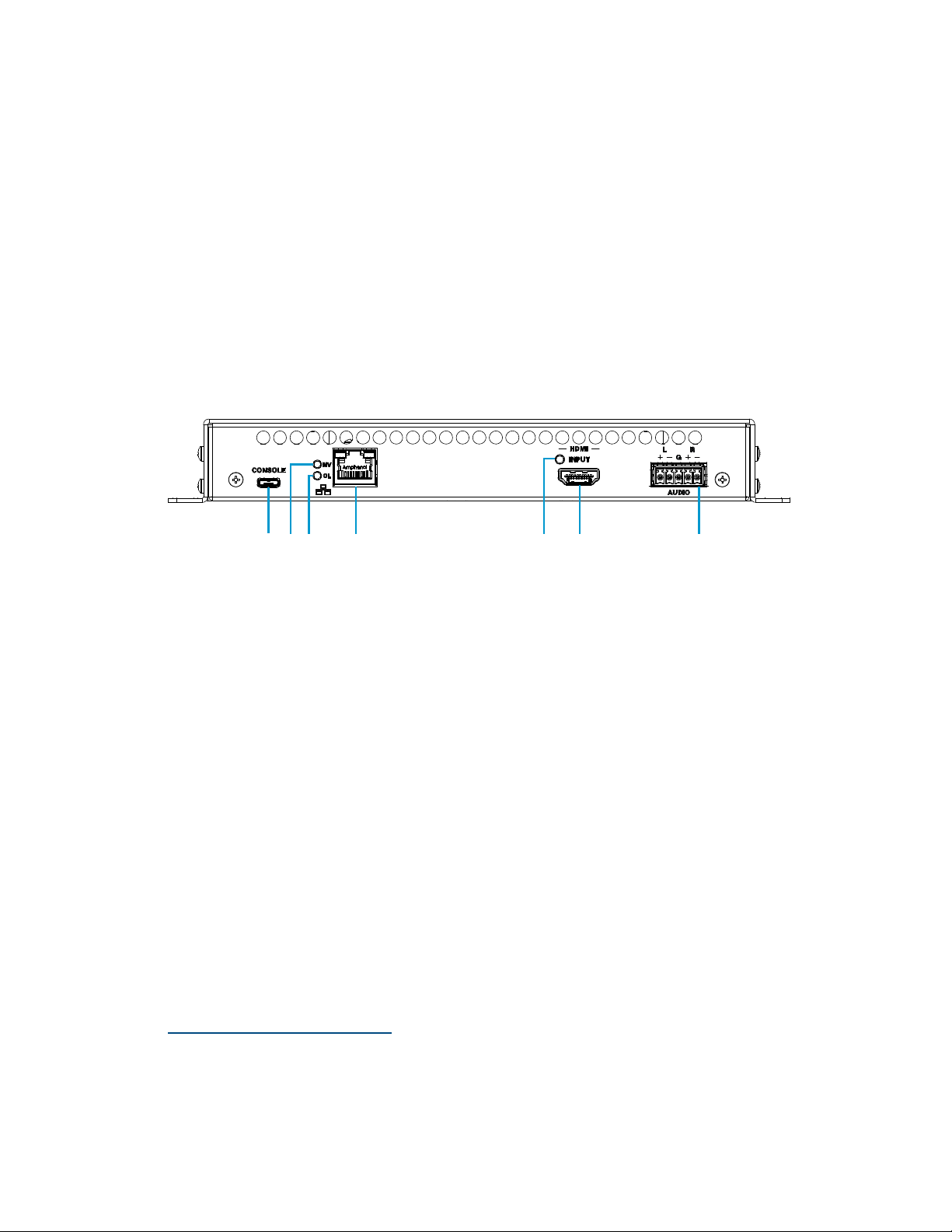
The following illustration shows the front panel of the DM-NVX-E30.
DM-NVX-E30 Front Panel
CONSOLE: Micro USB connector, female;
USB 2.0 computer console port for setup
NV LED: Green LED, indicates that the device is encoding (transmitting)
network video
OL LED: Green LED, indicates an online connection to a control system via Ethernet
LAN: 8-pin RJ-45 connector, female;
100BASE-TX/1000BASE-T Ethernet port;
PoE+ PD (powered device) port compatible with a PoE+ compliant Ethernet switch, a
Crestron DM-PSU-ULTRA-MIDSPAN, or an approved third-party PSE;
Green LED indicates Ethernet link status;
Amber LED indicates Ethernet activity
HDMI INPUT LED: Green LED, indicates sync detection at the HDMI® input
HDMI INPUT: HDMI Type A connector, female;
HDMI digital video/audio input (DVI and Dual-Mode DisplayPort™ interface
compatible)
2, 3
1
1
The LAN port must connect to a 1000BASE-T switch in order to stream network video.
2
The HDMI connection requires an appropriate adapter or interface cable to accommodate a DVI or
Dual-Mode DisplayPort signal. CBL-HD-DVI interface cables are sold separately.
3
Device control via CEC (Consumer Electronics Control) requires the use of a Crestron 3-Series® or later
control system.
2 • DM-NVX-E30(C)/DM-NVX-D30(C) Encoders/Decoders Product Manual – DOC. 8425A
AUDIO: 5-pin 3.5 mm detachable terminal block;
Balanced/unbalanced stereo line-level audio output;
Output Impedance: 200 Ohms balanced, 100 Ohms unbalanced;
Maximum Output Level: 4 Vrms balanced, 2 Vrms unbalanced
NOTE: The analog audio output is functional only when the DM-NVX-E30 is receiving
a 2-channel stereo input signal.
Front Panel, DM-NVX-D30
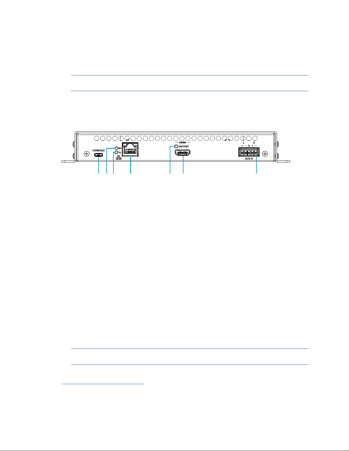
The following illustration shows the front panel of the DM-NVX-D30.
DM-NVX-D30 Front Panel
CONSOLE: Micro USB connector, female;
USB 2.0 computer console port for setup
NV LED: Green LED, indicates that the device is decoding (receiving) network video
OL LED: Green LED, indicates an online connection to a control system via Ethernet
LAN: 8-pin RJ-45 connector, female;
100BASE-TX/1000BASE-T Ethernet port;
PoE+ PD (powered device) port compatible with a PoE+ compliant Ethernet switch, a
Crestron DM-PSU-ULTRA-MIDSPAN, or an approved third-party PSE;
Green LED indicates Ethernet link status;
Amber LED indicates Ethernet activity
1
HDMI OUTPUT LED: Green LED, indicates video signal transmission at the
HDMI output
HDMI OUTPUT: HDMI Type A connector, female;
HDMI digital video/audio output (DVI compatible)
2, 3
AUDIO: 5-pin 3.5 mm detachable terminal block;
Balanced/unbalanced stereo line-level audio output;
Output Impedance: 200 Ohms balanced, 100 Ohms unbalanced;
Maximum Output Level: 4 Vrms balanced, 2 Vrms unbalanced
NOTE: The analog audio output is functional only when the DM-NVX-D30 is receiving
a 2-channel stereo input signal.
1
The LAN port must connect to a 1000BASE-T switch in order to stream network video.
2
The HDMI connection requires an appropriate adapter or interface cable to accommodate a DVI signal.
CBL-HD-DVI interface cables are sold separately.
3
Device control via CEC requires the use of a Crestron 3-Series or later control system.
Product Manual – DOC. 8425A DM-NVX-E30(C)/DM-NVX-D30(C) Encoders/Decoders • 3
Rear Panel, DM-NVX-E30 and DM-NVX-D30
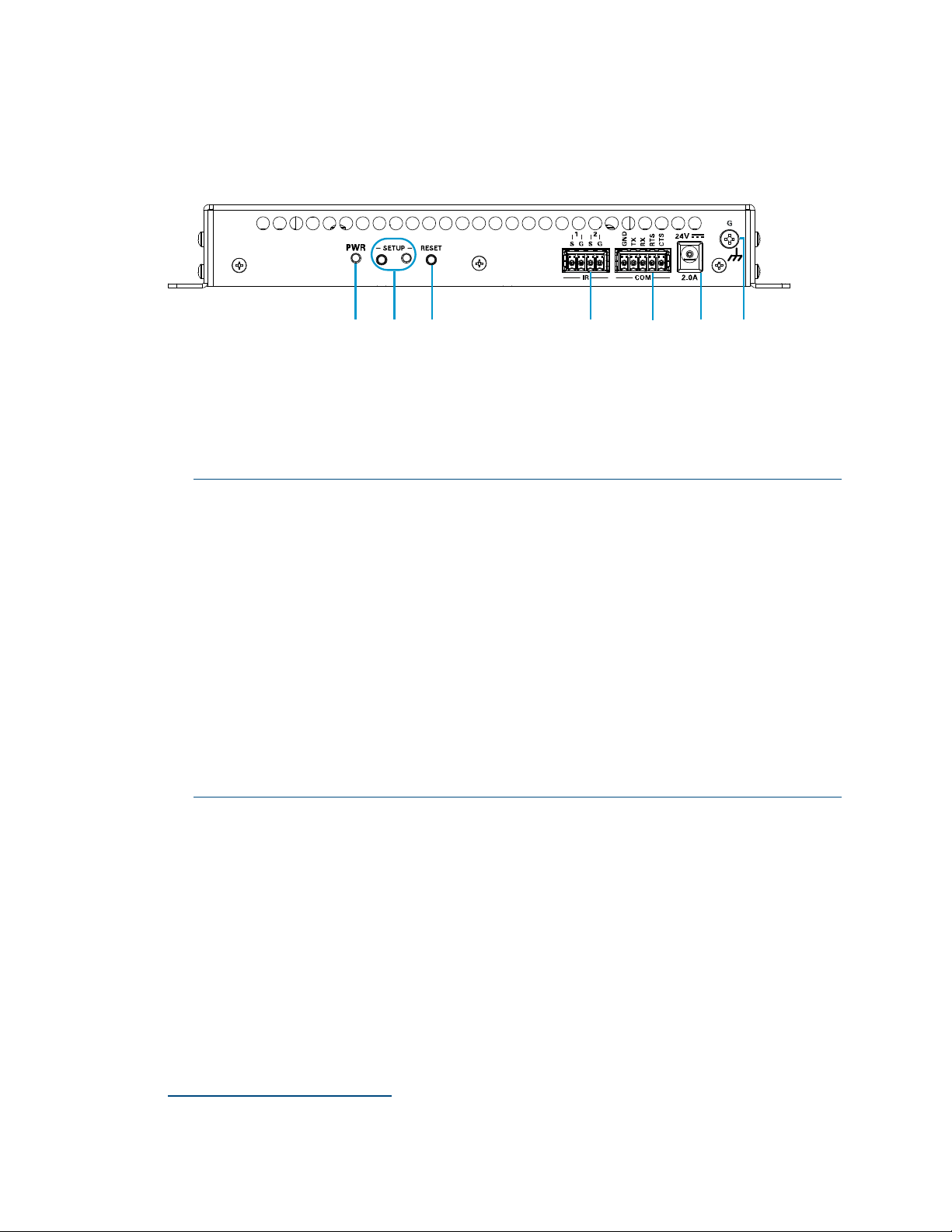
The following illustration shows the rear panel of the DM-NVX-E30 and DM-NVX-D30.
DM-NVX-E30 and DM-NVX-D30 Rear Panel
PWR: Bicolor green/amber LED, indicates operating power supplied via the power
pack (sold separately), PoE+ compliant Ethernet switch, or injector/PSE;
Lights amber while booting and green when operating
SETUP: Push button for on-screen display of IP address;
Red LED, indicates that the SETUP button is pressed and times out automatically.
NOTES:
• If the DM-NVX-D30 decoder is connected to a DM-NVX-E30(C) or
DM-NVX-35x(C) encoder, pressing the
for less than 10 seconds displays the decoder and encoder IP addresses.
The IP addresses are shown on the display connected to the HDMI output of
the decoder.
• If the DM-NVX-E30 encoder is connected to a DM-NVX-D30(C) decoder, pressing
the
SETUP button on the DM-NVX-E30 for less than 10 seconds displays the
encoder and decoder IP addresses. The IP addresses are shown on the display
connected to the HDMI output of the decoder.
• If the DM-NVX-E30 encoder is connected to a DM-NVX-35x(C) decoder,
pressing the
SETUP button on the DM-NVX-E30 displays the IP address of the
decoder only. The IP address is shown on the display connected to the HDMI
output of the decoder.
RESET: Recessed push button for hardware reset
IR 1–2: 4-pin 3.5 mm detachable terminal block;
Comprises two IR/serial ports
IR output up to 1.1 MHz;
1-way serial TTL/RS-232 (0–5 volts) up to 19200 baud;
Crestron IRP2 emitter sold separately
COM: 5-pin 3.5 mm detachable terminal block;
Bidirectional RS-232 port;*
Up to 115.2k baud, hardware and software handshaking support
SETUP button on the DM-NVX-D30
∗
∗
Device control via RS-232 and IR requires the use of a Crestron 3-Series or later control system.
4 • DM-NVX-E30(C)/DM-NVX-D30(C) Encoders/Decoders Product Manual – DOC. 8425A
24VDC 2.0A: 2.1 x 5.5 mm DC power connector;
24 VDC power input;
Power pack included
Ground: 6-32 screw, chassis ground lug
DM-NVX-E30C
The following illustration shows the connectors, controls, and indicators that are
available on the DM-NVX-E30C.
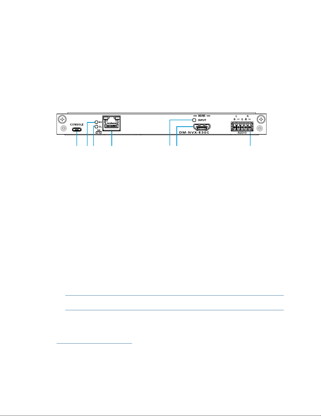
DM-NVX-E30C
CONSOLE: Micro USB connector, female;
USB 2.0 computer console port for setup
NV LED: Green LED, indicates that the device is encoding (transmitting)
network video.
OL LED: Green LED, indicates an online connection to a control system via Ethernet
LAN: 100BASE-TX/1000BASE-T Ethernet port;
Green LED indicates Ethernet link status;
Amber LED indicates Ethernet activity
HDMI INPUT LED: Green LED, indicates sync detection at the HDMI input
HDMI INPUT: HDMI Type A connector, female;
HDMI digital video/audio input (DVI and Dual-Mode DisplayPort interface
compatible)
2, 3
AUDIO: 5-pin 3.5 mm detachable terminal block;
Balanced/unbalanced stereo line-level audio output;
Output Impedance: 200 Ohms balanced, 100 Ohms unbalanced;
Maximum Output Level: 4 Vrms balanced, 2 Vrms unbalanced
NOTE: The analog audio output is functional only when the DM-NVX-E30C is
receiving a 2-channel stereo input signal.
1
1
The LAN port must connect to a 1000BASE-T switch in order to stream network video.
2
Device control via CEC requires the use of a Crestron 3-Series or later control system.
3
The HDMI connection requires an appropriate adapter or interface cable to accommodate a DVI or
Dual-Mode DisplayPort signal. CBL-HD-DVI interface cables are sold separately.
Product Manual – DOC. 8425A DM-NVX-E30(C)/DM-NVX-D30(C) Encoders/Decoders • 5
DM-NVX-D30C
The following illustration shows the connectors, controls, and indicators that are
available on the DM-NVX-D30C.
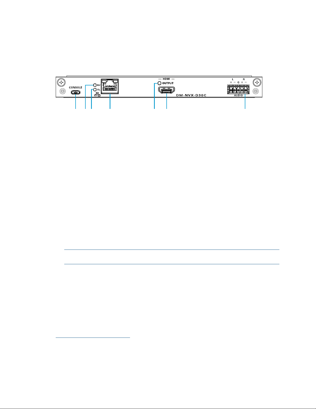
DM-NVX-D30C
CONSOLE: Micro USB connector, female;
USB 2.0 computer console port for setup
NV LED: Green LED, indicates that the device is decoding (receiving) network video.
OL LED: Green LED, indicates an online connection to a control system via Ethernet
LAN: 100BASE-TX/1000BASE-T Ethernet port;
1
Green LED indicates Ethernet link status;
Amber LED indicates Ethernet activity
HDMI OUTPUT LED: Green LED, indicates video signal transmission at the
HDMI output
HDMI OUTPUT: HDMI Type A connector, female;
HDMI digital video/audio output (DVI compatible)
2, 3
AUDIO: 5-pin 3.5 mm detachable terminal block;
Balanced/unbalanced stereo line-level audio output;
Output Impedance: 200 Ohms balanced, 100 Ohms unbalanced;
Maximum Output Level: 4 Vrms balanced, 2 Vrms unbalanced
NOTE: The analog audio output is functional only when the DM-NVX-D30C is
receiving a 2-channel stereo input signal.
1
The LAN port must connect to a 1000BASE-T switch in order to stream network video.
2
Device control via CEC requires the use of a Crestron 3-Series or later control system.
3
The HDMI connection requires an appropriate adapter or interface cable to accommodate a DVI signal.
CBL-HD-DVI interface cables are sold separately.
6 • DM-NVX-E30(C)/DM-NVX-D30(C) Encoders/Decoders Product Manual – DOC. 8425A

Configuration and Status
This section provides information about configuring or viewing the following items using
the web interface and SIMPL Windows as applicable:
• DMF-CI-8 chassis details
• DM NVX Director™ virtual switching appliance
• Stream statistics
• Multicast TTL (Time-to-Live)
• DSCP (Differentiated Services Code Point)
• EDID (Extended Display Identification Data)
• Subscriptions
• 7.1 surround sound audio
• Analog audio output
• Crestron XiO Cloud™ service connection
• Enterprise-grade security
• Fan control
• Automatic firmware update
DMF-CI-8 Chassis Details
NOTE: DMF-CI-8 chassis details apply to the DM-NVX-E30C and DM-NVX-D30C only.
A DM NVX card occupies a DMF-CI-8 chassis. Information about the chassis can be
viewed using the web interface or SIMPL Windows.
Using the Web Interface
View DMF-CI-8 chassis information on the Status page. The Chassis Details section
displays the following information:
• Serial number of the chassis
• Number of the slot into which the card is installed
Product Manual – DOC. 8425A DM-NVX-E30(C)/DM-NVX-D30(C) Encoders/Decoders • 7
 Loading...