

Crestron DM-NVX-350, DM-NVX-351, DM-NVX-351C, DM-NVX-350C Product Manual

DM-NVX Series
DigitalMedia™ 4K60 4:4:4 HDR
Network AV Encoders/Decoders
Product Manual
Crestron Electronics, Inc.

The product warranty can be found at www.crestron.com/warranty.
The specific patents that cover Crestron products are listed at www.crestron.com/legal/patents.
Certain Crestron products contain open source software. For specific information, please visit www.crestron.com/opensource.
Crestron, the Crestron logo, Crestron Toolbox, and DigitalMedia are either trademarks or registered trademarks of Crestron Electronics, Inc.
in the United States and/or other countries. Dolby and Dolby Atmos are either trademarks or registered trademarks of Dolby Laboratories in
the United States and/or other countries. DTS HD and DTS:X are either trademarks or registered trademarks of DTS, Inc. in the United States
and/or other countries. HDMI is either a trademark or registered trademark of HDMI Licensing LLC in the United States and/or other
countries. Other trademarks, registered trademarks, and trade names may be used in this document to refer to either the entities claiming the
marks and names or their products. Crestron disclaims any proprietary interest in the marks and names of others. Crestron is not responsible
for errors in typography or photography.
This document was written by the Technical Publications department at Crestron.
©2017 Crestron Electronics, Inc.

Contents
Introduction 1
Physical Description 2
DM-NVX-350 and DM-NVX-351 .................................................................................... 2
Front Panel.............................................................................................................. 2
Rear Panel .............................................................................................................. 3
DM-NVX-350C and DM-NVX-351C ............................................................................... 4
Configuration 6
Encoding and Decoding Functionality ............................................................................ 6
Configuration Using the Web Interface .................................................................... 7
Configuration Using SIMPL Windows ...................................................................... 7
Stream Statistics ........................................................................................................... 7
Configuration Using the Web Interface .................................................................... 8
Configuration Using SIMPL Windows ...................................................................... 8
Automatic Routing of Video Inputs ................................................................................. 8
Configuration Using the Web Interface .................................................................... 8
Configuration Using SIMPL Windows ...................................................................... 9
Video Wall Processing ................................................................................................... 9
Configuration Using the Web Interface .................................................................... 9
Configuration Using SIMPL Windows .................................................................... 10
Adjustable Underscan.................................................................................................. 10
Configuration Using the Web Interface .................................................................. 11
Configuration Using SIMPL Windows .................................................................... 11
User-Selectable Output Resolution .............................................................................. 11
Configuration Using the Web Interface .................................................................. 11
Configuration Using SIMPL Windows .................................................................... 12
Maximum Color Depth and Color Space Mode ........................................................... 12
Configuration Using the Web Interface .................................................................. 12
Configuration Using SIMPL Windows .................................................................... 13
EDID ............................................................................................................................ 13
Subscriptions ............................................................................................................... 14
Configuration Using the Web Interface .................................................................. 15
Configuration Using SIMPL Windows .................................................................... 16
Daisy Chain Configuration ............................................................................................ 16
Switching Subscribed Transmitters ....................................................................... 17
Switching Nonsubscribed Transmitters ................................................................. 17
7.1 Surround Sound Audio .......................................................................................... 18
Analog Audio Input or Output ...................................................................................... 18
Configuration Using the Web Interface .................................................................. 19
Configuration Using SIMPL Windows .................................................................... 20
Breakaway Audio ......................................................................................................... 20
Configuration Using the Web Interface .................................................................. 20
Configuration Using SIMPL Windows .................................................................... 20
Product Manual – DOC. 7839D Contents • i

USB 2.0 Routing.......................................................................................................... 21
Configuration Using the Web Interface .................................................................. 21
Configuration Using SIMPL Windows .................................................................... 22
HDCP 2.2 Compliance 23
IGMP Snooping 24
Troubleshooting 26
Appendix: Device Discovery 29
ii • Contents Product Manual – DOC. 7839D

DM-NVX Series:
DigitalMedia™ 4K60 4:4:4 HDR
Network AV Encoders/Decoders
Introduction
The Crestron® DM-NVX series transports ultra high-definition 4K video with 60 Hz frame
rates and 4:4:4 color sampling over standard Gigabit Ethernet. Support for high dynamic
range video (HDR10) and HDCP 2.2 ensures high picture quality and compatibility with a
variety of media sources. The DM-NVX series uses JPEG 2000 compression and encoding,
achieving a low end-to-end latency of 30 ms at 60 fps. The DM-NVX series accepts SFP
(Small Form-factor Pluggable) transceiver modules (Crestron SFP-1G series), which support
multimode and single-mode fiber.
The DM-NVX series consists of the DM-NVX-350 and DM-NVX-351 stand-alone endpoints
and the DM-NVX-350C and DM-NVX-351C cards. The cards are designed to occupy the
DMF-CI-8 card chassis. The DM-NVX-351 and DM-NVX-351C provide the same
functionality as the DM-NVX-350 and DM-NVX-350C with the addition of surround sound to
stereo downmixing.
This manual provides information about the following:
• Physical description of the connectors, controls, and indicators on the DM-NVX
series
• Configuration of some of the capabilities of the DM-NVX series, for example,
encoding and decoding functionality
• HDCP 2.2 compliance
• IGMP snooping
• Troubleshooting guidelines
In addition, information about device discovery of a DM-NVX device using Crestron
Toolbox™ software is provided in the appendix of this manual. For installation information,
refer to the DM-NVX-350/DM-NVX-351 DO Guide (Doc. 7799) and the DM-NVX-350C/
DM-NVX-351C DO Guide (Doc. 7975). For information about designing a network for a
DM-NVX system, refer to the DigitalMedia™ NVX Series Design Guide (Doc. 7977).
The manuals are available at www.crestron.com/manuals
.
Product Manual – DOC. 7839D DM-NVX Series: 4K60 4:4:4 HDR Network AV Encoders/Decoders • 1
Physical Description
The following sections provide information about the connectors, controls, and indicators
that are available on the DM-NVX series.
DM-NVX-350 and DM-NVX-351
This section provides information about the connectors, controls, and indicators that
are available on the front and rear panels of the DM-NVX-350 and DM-NVX-351
stand-alone endpoints.
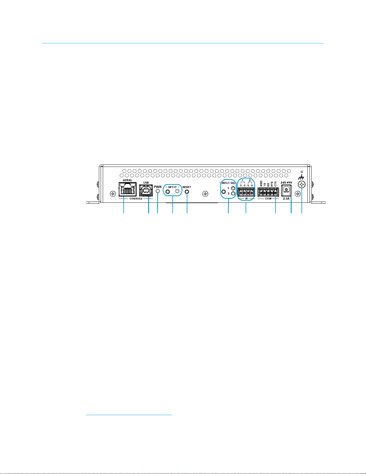
Front Panel
The following illustration shows the front panel of the DM-NVX-350 and DM-NVX-351.
DM-NVX-350 and DM-NVX-351 Front Panel
CONSOLE, SERIAL: 8-pin RJ-45 female;
RS-232 computer console port (for setup)
CONSOLE, USB: USB Type B female;
USB 2.0 computer console port (for setup)
PWR: Bicolor green/amber LED, indicates operating power supplied via the power
pack or injector, turns amber while booting and green when operating
SETUP: Red LED and push button for Ethernet setup
RESET: Recessed push button for hardware reset
INPUT SEL: Push button for manual input selection and two bicolor green/amber LEDs
that indicate the current active input and signal presence at each corresponding input
IR 1–2: 4-pin 3.5 mm detachable terminal block;
Comprises two IR/serial ports*
IR output up to 1.1 MHz;
1-way serial TTL/RS-232 (0–5 volts) up to 19200 baud
COM: 5-pin 3.5 mm detachable terminal block;
Bidirectional RS-232 port;*
Up to 115.2k baud, hardware and software handshaking support
24VDC 2.0A: 2.1 x 5.5 mm dc power connector;
24 Vdc power input;
Power pack included
Ground: 6-32 screw;
Chassis ground lug
* Device control via RS-232, IR, CEC, or Ethernet requires integration with a Crestron control system.
2 • DM-NVX Series: 4K60 4:4:4 HDR Network AV Encoders/Decoders Product Manual – DOC. 7839D
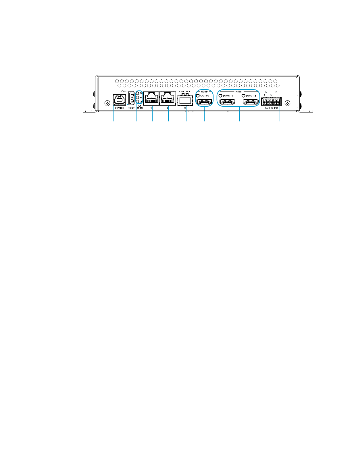
Rear Panel
The following illustration shows the rear panel of the DM-NVX-350 and DM-NVX-351.
DM-NVX-350 and DM-NVX-351 Rear Panel
DEVICE: USB Type B female;
USB 2.0 device port;
USB signal extender port for connection to a computer or any other USB 2.0 host
HOST: USB Type A female;
USB 2.0 host port;
USB signal extender port for connection of a mouse, keyboard, or any other
USB 2.0 device;
Available Power: 500 mA at 5 Vdc
1
1
TX, RX, and OL LEDs: Green TX LED indicates that unit is in transmitter (encoder)
mode;
Green RX LED indicates that unit is in receiver (decoder) mode;
Green OL LED indicates an online connection to a control system via Ethernet
LAN 1: 8-pin RJ-45 female;
10BASE-T/100BASE-TX/1000BASE-T Ethernet port;
PD (powered device) port compatible with Crestron DM-PSU-ULTRA-MIDSPAN;
Green LED indicates Ethernet link status;
Amber LED indicates Ethernet activity
LAN 2: 8-pin RJ-45 female;
10BASE-T/100BASE-TX/1000BASE-T Ethernet port;
Green LED indicates Ethernet link status;
Amber LED indicates Ethernet activity
1
Either the DEVICE port or the HOST port can be used at one time—both ports cannot be used simultaneously.
2
Either LAN 1 or LAN 2 can be used as the primary LAN connection, allowing the other port to be used for
connection to a local network device or to another DM-NVX device. If one of the ports is used as the primary
LAN connection, the port requires connection to a 1000BASE-T switch in order to stream network video.
3
The DM-NVX-350 and DM-NVX-351 can be powered by the connection of LAN 1 to a Crestron
DM-PSU-ULTRA-MIDSPAN or other Crestron approved power injector (sold separately). Refer to Online Help
Answer ID 5791 for additional information. The DM-NVX-350 and DM-NVX-351 can also be powered using the
included power pack.
2
3
2
Product Manual – DOC. 7839D DM-NVX Series: 4K60 4:4:4 HDR Network AV Encoders/Decoders • 3
LAN 3: SFP port;
1
Accepts one Crestron SFP-1G series SFP transceiver module;
Green LINK LED indicates Ethernet link status;
Green ACT LED indicates Ethernet activity
HDMI OUTPUT: 19-pin Type A HDMI
HDMI digital video/audio output (DVI compatible);
Green LED indicates video signal transmission at the HDMI output
®
female connector;
2
HDMI INPUTS 1–2: 19-pin Type A HDMI female connectors;
HDMI digital video/audio inputs (DVI and Dual-Mode DisplayPort compatible);
Two green LEDs, each indicates sync detection at the corresponding HDMI input
2
AUDIO I/O: 5-pin 3.5 mm detachable terminal block;
Balanced/unbalanced stereo line-level audio input or output;
Input Impedance: 24k Ohms balanced/unbalanced;
Maximum Input Level: 4 Vrms balanced, 2 Vrms unbalanced;
Output Impedance: 200 Ohms balanced, 100 Ohms unbalanced;
Maximum Output Level: 4 Vrms balanced, 2 Vrms unbalanced
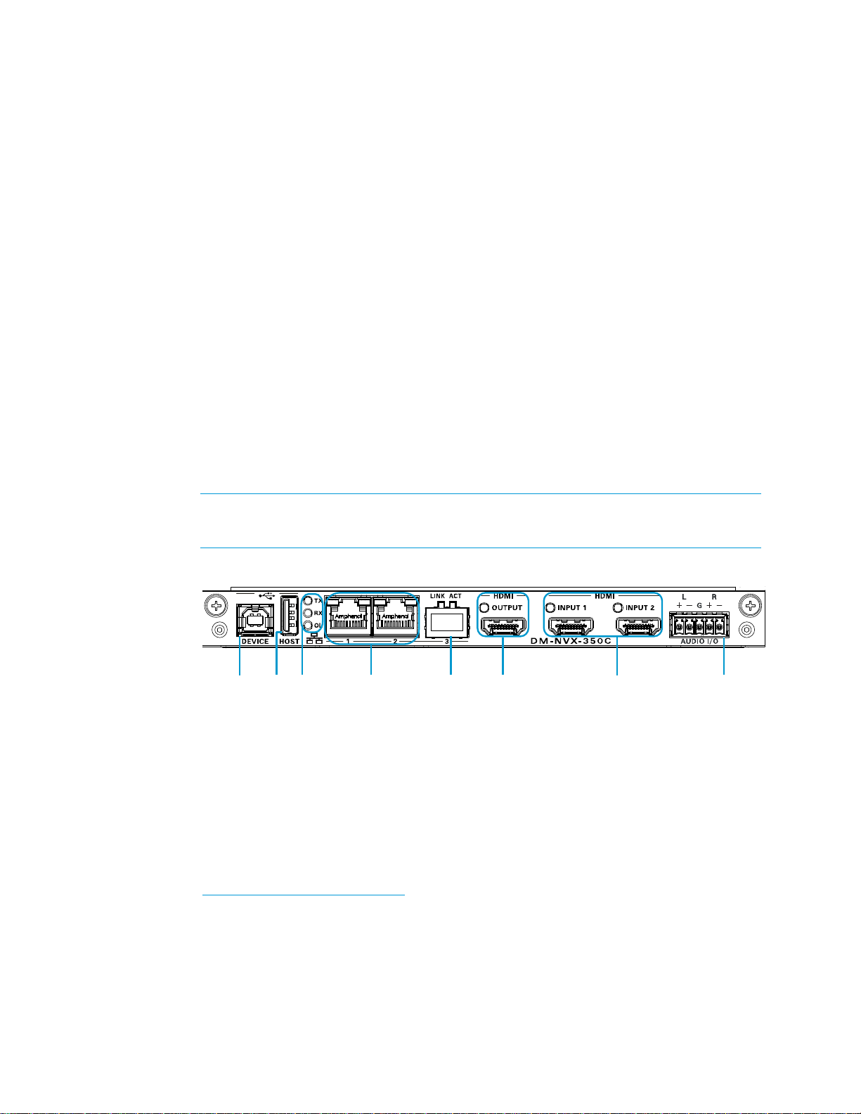
DM-NVX-350C and DM-NVX-351C
The following illustration shows the connectors, controls, and indicators that are available on
the DM-NVX-350C.
NOTE: For illustrative purposes, only the DM-NVX-350C is shown below.
The DM-NVX-351C contains the same connectors, controls, and indicators as the
DM-NVX-350C.
DM-NVX-350C
DEVICE: USB Type B female;
USB 2.0 device port;
USB signal extender port for connection to a computer or any other USB 2.0 host
HOST: USB Type A female;
USB 2.0 host port;
USB signal extender port for connection of a mouse, keyboard, or any other
USB 2.0 device;
Available Power: 500 mA at 5 Vdc
1
LAN 3 can be used as the primary LAN connection or can be connected to another DM-NVX device. LAN 3 can
connect to a fiber-optic network using the appropriate Crestron SFP-1G transceiver module (sold separately).
Refer to the SFP-1G Series Installation Guide (Doc. 7979) for information about installing Crestron SFP-1G series
transceiver modules.
2
HDMI connections require an appropriate adapter or interface cable to accommodate a DVI or Dual-Mode
DisplayPort signal. CBL-HD-DVI interface cables are sold separately.
3
Either the DEVICE port or the HOST port can be used at one time—both ports cannot be used simultaneously.
3
3
4 • DM-NVX Series: 4K60 4:4:4 HDR Network AV Encoders/Decoders Product Manual – DOC. 7839D

TX, RX, and OL LEDs: Green TX LED indicates that unit is in transmitter (encoder)
mode;
Green RX LED indicates that unit is in receiver (decoder) mode;
Green OL LED indicates an online connection to a control system via Ethernet
LAN 1–2: 8-pin RJ-45 female;
10BASE-T/100BASE-TX/1000BASE-T Ethernet ports
Green LED indicates Ethernet link status;
Amber LED indicates Ethernet activity
LAN 3: SFP port;
Accepts one Crestron SFP-1G series SFP transceiver module;
Green LINK LED indicates Ethernet link status;
Green ACT LED indicates Ethernet activity
HDMI OUTPUT: 19-pin Type A HDMI female;
HDMI digital video/audio output (DVI compatible)
HDMI INPUTS 1–2: 19-pin Type A HDMI female;
HDMI digital video/audio inputs (DVI and Dual-Mode DisplayPort compatible)
AUDIO I/O: 5-pin 3.5 mm detachable terminal block;
Balanced/unbalanced stereo line-level audio input or output;
Input Impedance: 24k Ohms balanced/unbalanced;
Maximum Input Level: 4 Vrms balanced, 2 Vrms unbalanced;
Output Impedance: 200 Ohms balanced, 100 Ohms unbalanced;
Maximum Output Level: 4 Vrms balanced, 2 Vrms unbalanced
1
2
3
3
1
Either LAN 1 or LAN 2 can be used as the primary LAN connection, allowing the other port to be used
for connection to a local network device or to another DM-NVX device. If one of the ports is used as the primary
LAN connection, the port requires connection to a 1000BASE-T switch in order to stream network video.
2
LAN 3 can be used as the primary LAN connection or can be connected to another DM-NVX device. LAN 3 can
connect to a fiber-optic network using the appropriate Crestron SFP-1G transceiver module (sold
separately). Refer to the SFP-1G Series Installation Guide (Doc. 7979) for information about installing Crestron
SFP-1G series transceiver modules.
3
HDMI connections require an appropriate adapter or interface cable to accommodate a DVI or Dual-Mode
DisplayPort signal. CBL-HD-DVI interface cables are sold separately.
Product Manual – DOC. 7839D DM-NVX Series: 4K60 4:4:4 HDR Network AV Encoders/Decoders • 5

Configuration
The DM-NVX series can be configured using the web interface, which can be accessed
from a web browser by entering the IP address or hostname of the device. SIMPL Windows
can also be used to configure the DM-NVX series.
This section provides information about configuration of the following items using the web
interface or SIMPL Windows:
• Encoding and decoding functionality
• Stream statistics
• Automatic routing of video inputs
• Video wall processing
• Adjustable underscan
• User-selectable output resolution
• Maximum color depth and color space mode
• EDID
• Subscriptions
• Daisy chain
• 7.1 Surround sound audio
• Analog audio input or output
• Breakaway audio
• USB 2.0 routing
Encoding and Decoding Functionality
A DM-NVX device can be configured to function as a network AV encoder (transmitter) or
decoder (receiver):
• As an encoder, a DM-NVX device allows a laptop computer, camera, or other
media source to be connected via an HDMI cable and then transmitted over the
network.
• As a decoder, a DM-NVX device receives the signal from a DM-NVX encoder and
feeds the signal to a display device via the HDMI output. A DM-NVX decoder can
switch among multiple DM-NVX encoders on the network alongside locally
connected HDMI sources.
To configure a DM-NVX device as an encoder or decoder, use the web interface or SIMPL
Windows as discussed in the following sections.
6 • DM-NVX Series: 4K60 4:4:4 HDR Network AV Encoders/Decoders Product Manual – DOC. 7839D
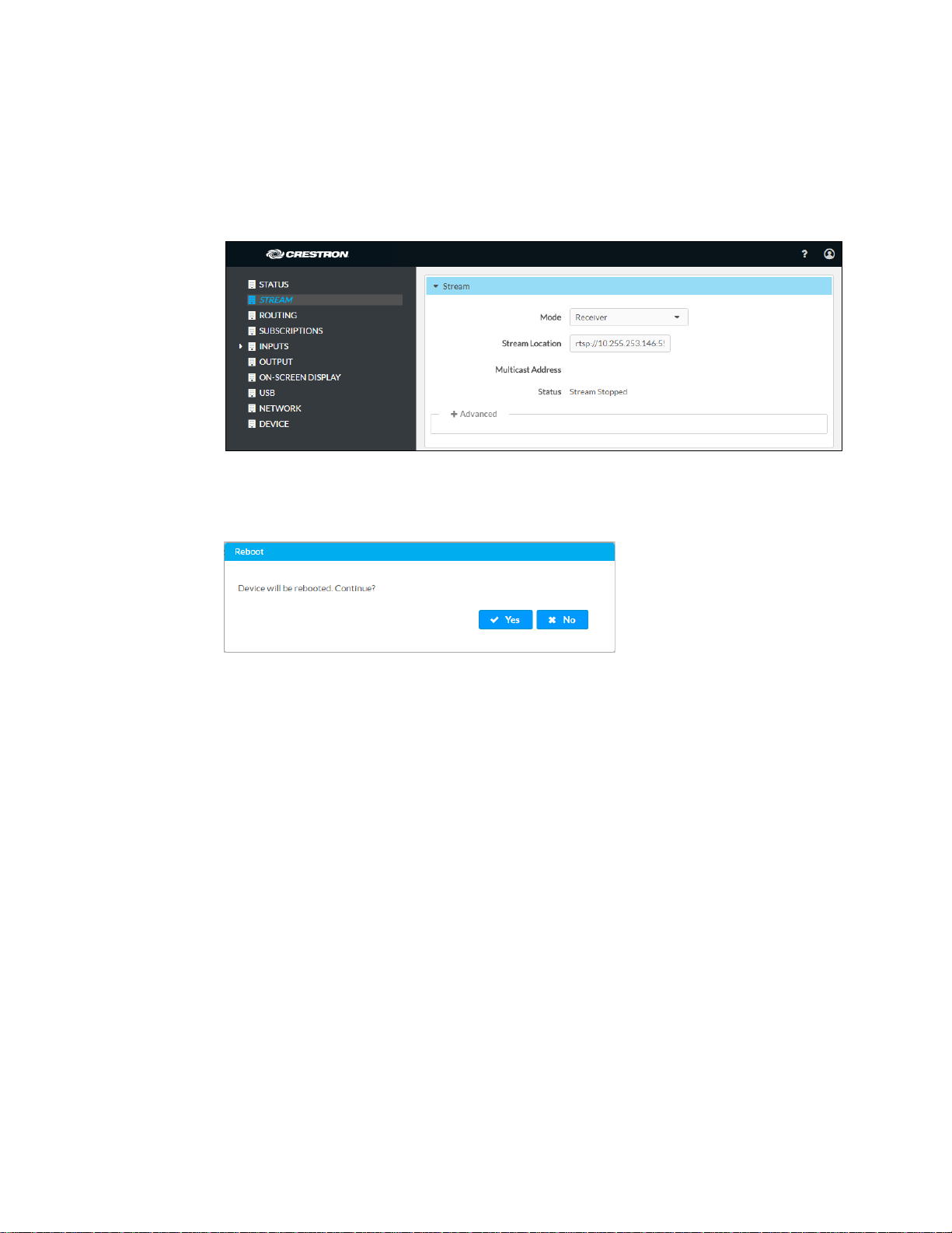
Configuration Using the Web Interface
Configure a DM-NVX device as an encoder or decoder on the Stream page of the web
interface. In the
Receiver (decoder).
Stream Page - Encoder (Transmitter) or Decoder (Receiver) Configuration
When a different mode is selected, a prompt appears asking for confirmation that the device
be rebooted. Click
Mode drop-down list, select Receiver or Transmitter. The default setting is
Yes to reboot the device.
Device Reboot Prompt
For additional information, refer to the online help of the web interface.
Configuration Using SIMPL Windows
Using top-level programming for the DM-NVX device, set the <DeviceMode> analog input
join to the desired mode (
Changing modes requires that the device be rebooted. Trigger the <Reboot> digital
input join to reboot the device. For additional information, refer to the SIMPL Windows
help file.
Receiver or Transmitter). The default setting is Receiver.
Stream Statistics
Statistics can be displayed to indicate the number of packets received or transmitted, the
number of dropped packets, and the bit rate of the received or transmitted stream.
To enable or disable stream statistics, use the web interface or SIMPL Windows as
discussed in the following sections.
Product Manual – DOC. 7839D DM-NVX Series: 4K60 4:4:4 HDR Network AV Encoders/Decoders • 7
 Loading...