

Page 1

Crestron® DM-MD6X4/DM-MD6X6
DigitalMedia™ Distribution Center
Installation & Operation Guide
Page 2

This document was prepa red and written by the Technical Publications department at:
Crestron Electronics, Inc.
15 Volvo Drive
Rockleigh, NJ 07647
1-888-CRESTRON
The product warranty can be found at www.crestron.com/warranty
The specific patents that cover Crestron products can be found at patents.crestron.com
Certain Crestron products contain open source software. For more information, please visit www.crestron.com/opensource
.
.
.
Crestron, the Crestron logo, Auto-Locking, Crestron Toolbox, DigitalMedia, DigitalMedia 8G, DigitalMedia 8G+, DM, DM 8G+, QuickSwitch HD,
PROCISE, and SystemBuilder are either trademarks or registered trademarks of Crestron Electronics, Inc. in the United States and/or other countries.
Blu-ray Disc is either a trademark or a registered trademark of the Blu-ray Disc Association in the United States and/or other countries. Dolby and
Dolby Digital are either trademarks or registered trademarks of Dolby Laboratories in the United States and/or other countries. DTS, DTS HD, and
DTS HD Master Audio are either trademarks or registered trademarks of DTS, Inc. in the United States and/or other countries. HDBaseT and the
HDBT logo are either trademarks or registered trademarks of the HDBaseT Alliance in the United States and/or other countries. HDMI and the
HDMI logo are either trademarks or registered trademarks of HDMI Licensing, LLC in the United States and/or other countries. Windows is either a
trademark or a registered trademark of Microsoft Corporation in the United States and/or other countries. UL and the UL logo are either trademarks or
registered trademarks of Underwriters Laboratories, Inc., in the United States and/or other countries. Other trademarks, registered trademarks, and
trade names may be used in this document to refer to either the entities claiming the marks and names or their products. Crestron disclaims any
proprietary interest in the marks and names of others. Crestron is not responsible for errors in typography or photography.
©2017 Crestron Electronics, Inc.
Page 3

Crestron DM-MD6X4/DM-MD6X6 DigitalMedia Distribution Center
Contents
DigitalMedia™ Dis tribution Cente r: DM-MD6X4/DM-MD6X6 1
Introduction ............................................................................................................................... 1
Features and Functions ................................................................................................ 1
Applications................................................................................................................. 5
Internal Block Diagram ............................................................................................... 6
Specifications .............................................................................................................. 7
Physical Description .................................................................................................. 10
Setup ........................................................................................................................................ 16
Network Wiring ......................................................................................................... 16
Ethernet Setup ........................................................................................................... 16
Identity Code ............................................................................................................. 17
Installation ................................................................................................................. 17
Hardware Hookup ..................................................................................................... 19
Configuration and Status ......................................................................................................... 21
Accessing Installer Mode .......................................................................................... 21
Inputs ......................................................................................................................... 23
Outputs ...................................................................................................................... 24
Network ..................................................................................................................... 25
Control ....................................................................................................................... 29
Exiting Installer Mode ............................................................................................... 31
Programming Software ............................................................................................................ 32
Earliest Version Software Requirements for the PC ................................................. 32
Programming with SystemBuilder ............................................................................ 32
Programming with SIMPL Windows ........................................................................ 32
Uploading and Upgrading ........................................................................................................ 36
Establishing Communication ..................................................................................... 36
Programs and Firmware ............................................................................................ 37
Program Checks ........................................................................................................ 38
DMTool ..................................................................................................................... 38
Operation ................................................................................................................................. 39
Routing an Input Signal to Output(s) ........................................................................ 39
Disconnecting Routed Signal(s) ................................................................................ 40
Problem Solving ...................................................................................................................... 41
Troubleshooting ......................................................................................................... 41
Reference Documents ................................................................................................ 42
Further Inquiries ........................................................................................................ 42
Future Updates .......................................................................................................... 42
Installation & Operation Guide – DOC. 7196B Contents • i
Page 4

Page 5

Crestron DM-MD6X4/DM-MD6X6 DigitalMedia Distribution Center
• Provides a low-cost, high-performance multiroom HD AV signal
DigitalMedia™ Distribution Center:
DM-MD6X4/DM-MD6X6
Introduction
The Crestron® DM-MD6X4 and DM-MD6X6 DigitalMedia™ distribution centers
distribute multiple high-definition sources to up to four rooms (DM-MD6X4) or up
to six rooms (DM-MD6X6) as part of a complete Crestron system. Featuring
DigitalMedia 8G+
ultra high-bandwidth signal routing over CAT5e (or better) wiring
®
technology, the DM-MD6X 4 a nd DM-MD6X6 deliver
1
.
Features and Functions
routing solution
• Distributes uncompressed digital video and audio over CAT5e
(or better) twisted-pair wire
• Affords a true one-wire solution using DigitalMedia 8G+ technology
• HDBaseT
HDBaseT certified equipment
• Features independently switchable HDBaseT or DM 8G+
three (DM-MD6X4) or five (DM-MD6X6) remote displays
• Allows up to a 330-foot (100-meter) wire distance to each display
• Includes one HDMI
• Provides inputs for six HDMI, DVI, or DisplayPort Multimode sources
• Handles video resoluti ons up to Full HD 1080p
• Handles computer resolutions up to WUXGA
• Handles 3D video and Deep Color
• Handles Dolby
(Continued on following page)
linear PCM audio
• HDCP compliant
• QuickSwitch HD™ technology manages HDCP keys for fast, reliable
switching
1
®
Alliance Certified–Enables direct connection to other
®
outputs for
®
output for a local display or audio processor
®
TrueHD audio, DTS HD® audio, and uncompre ss e d 7.1
2
1. For DM 8G+ or HDBaseT wiring up to 330 feet (100 meters) between devices, use Crestron
DM-CBL-8G DigitalMedia 8G™ cable or generic CAT5e (or better) UTP or STP. Shielded cable and
connectors are recommended to safeguard against unpredictable environmental electrical noise that
may impact performance at resolutions above 1080p. For complete system design guidelines, refer to
the Crestron DigitalMedia Design Guide (Doc. 4546) at www.crestron.com/manuals
cables are sold separately.
2. HDMI requires an appropriate adapter or interface cable to accommodate a DVI or DisplayPort
Multimode signal. Crestron CBL-HD-DVI interface cables are sold separately.
Installation & Operation Guide – DOC. 7196B DigitalMedia Distribution Center: DM-MD6X4/DM-MD6X6 • 1
. All wire and
Page 6

DigitalMedia Distribution Center Crestron DM-MD6X4/DM-MD6X6
• Auto-Locking® technology achieves rapid switching between disparate
Features and Functions
(Continued)
sources
• Performs automatic AV signal format management via EDID
• Allows independent scaling for every display through select
• Enables USB HID mouse and keyboard signal extension
• Expanded USB routing capabilities available using USB-EXT-DM USB
• Includes integrated Ethernet switch
• Private Network Mode–Requires only one IP address for the complete
• Provides Power over DM for PoDM compatible receivers
• Provides setup and diagnostics tools via front panel or software
• Includes built-in uni ve rs a l power supply
• Allows native Crestron system integration via Ethernet
• Standard component wi dth or two-space rack mountable
®
receivers3
DM
over Ethernet extenders
DM system
4
HD Matrix Switcher
The DM-MD6X4 and DM-MD6X6 provide six HDMI® inputs to handle HDTV
receivers, DVD or Blu-ray Disc
digital sources. Outputs include one HDMI and three (DM-MD6X4) or five
(DM-MD6X6) DigitalMedia ports, furnishing simple one-wire connectivity for a
local display or audio processor, and three (DM-MD6X4) or five (DM-MD6X6)
additional displays any where in the house. QuickSwitch HD™ matrix switching
allows any display to view any source at any time.
DigitalMedia 8G+
Crestron exclusive DM 8G+® technology affords the ultimate in simplicity,
providing a true one-wire interface for distributing high-definition video, audio, and
control signals to multiple displays throughout a residence or commercial structure.
Simply connect a DM 8G+ receiver
projector for a complete AV and control interface. Only one CAT5e (or better) wire
run to each receiver transports pure, uncompressed HD video, 7.1 surround sound
audio, 10/100 Etherne t , power, and control signals for a fully integrated media
system with minimal wiring. DM 8G+ allows for wire runs up to 330 feet (100
meters) using CAT5e (or better) or Crestron DigitalMedia 8G™ cable.
3. DM 8G+ receivers with built-in scaling include the DM-RMC-SCALER-C, DM-RMC-200-C,
DM-RMC-4K-SCALER-C, and DM-RMC-4K-SCALER-C-DSP. For the HDMI output, use the
HD-SCALER-HD-E or the HD-SCALER-VGA-E.
4. USB-EXT DM USB over Ethernet extender modules are sold separately. Refer to the USB-EXT-
DM spec sheet on the product webpage for more information.
* For DM 8G+ or HDBaseT wiring up to 330 feet (100 meters) between devices, use Crestron
DM-CBL-8G DigitalMedia 8G cable or generic CAT5e (or better) UTP or STP. Shielded cable and
connectors are recommended to safeguard against unpredictable environmental electrical noise that
may impact performance at resolutions above 1080p. For complete system design guidelines, refer to
the Crestron DigitalMedia Design Guide (Doc. 4546). All wire and cables are sold separately.
®
players, media servers, computers, and other HD
(sold separately) at each flat-panel display or
*
2 • DigitalMedia Distribution Center: DM-MD6X4/DM-MD6X6 Installation & Operation Guide – DOC. 7196B
Page 7

Crestron DM-MD6X4/DM-MD6X6 DigitalMedia Distribution Center
HDBaseT® Alliance Certified
Crestron DigitalMedia 8G+ technology is designed using HDBaseT Alliance
specifications, ensuring interoperability with other HDBaseT certified products. Via
its DM 8G+ outputs, the DM-MD6X4 and DM-MD6X6 can be connected directly to
HDBaseT compliant display devices without requiring any DM
Quickswitch HD
Handling high-definition digital media means handling HDCP (High-bandwidth
Digital Content Protection), which is the encryption scheme that content providers
use to protect their DVDs, Blu-ray Discs, and broadcast signals against unauthorized
copying. Viewing HDCP encrypted content requires the source device to
"authenticate" each display in the system and to issue it a key before the content can
be viewed. Ordinarily, this process causes a complete loss in signal for up to
15 seconds each time a new source or display is selected anywhere in the system.
Additionally, every source device has a limited number of keys available, so if too
many devices are connected, the source stops outputting a signal without warning.
Crestron Quickswitch HD solves this problem by managing keys for every
HDCP-compliant device in the system, maintaining continuous authentication for
each device to ensure fast, reliable routing of any source to any number of disp la y
devices.
®
receivers.
Auto-Locking® Technology
Crestron Auto-Locking technology enables high-speed signal switching by
instantaneously configuring every device in the signal path as soon as the signal
reaches the first device. Whether switching between sources or TV channels,
Auto-Locking significantly reduces the time it takes each device to sense the new
signal and to configure itself to handle the changes, virtually eliminating any
noticeable gap while switching.
EDID Format Management
The DM-MD6X4 and DM-MD6X6 manage the EDID (Ext e nded Display
Identification Data) that modern digital devices use to communicate their
capabilities. Through the DM-MD6X4 and DM-MD6X6, the format and resolut i on
capabilities of each device can be assessed, allowing the installer to configure EDID
signals appropriately for the most desirable and predictable behavior.
A Scaler for Every Display
Scaling capability can be added to the DM-MD6X4 and DM-MD6X6 using select
DM 8G+ receivers (sold separately) with built-in HD and 4K scalers.
independent high-performance scaler at every display device, DigitalMedia truly
delivers the most flexible and user-friendly solution for routing multiple disparate
sources to many different display devices. This “Distributed Scaler Approach”
ensures an optimal image on every screen no matter what sources are selected.
Distributed scaling allows a high-resolution computer source to be viewed on any
display in the building, and allows a high-definition 3D source to be viewed on lower
resolution 2D displays wi thout compromising the original signa l , such as letting a
home theater’s Full HD 1080p 3D image be shared with smaller, lesser displays in
other rooms.
*
By placing an
* DM 8G+ receivers with built-in scaling include the DM-RMC-SCALER-C, DM-RMC-200-C,
DM-RMC-4K-SCALER-C, and DM-RMC-4K-SCALER-C-DSP. For the HDMI output, use the HDSCALER-HD-E or HD-SCALER-VGA-E.
Installation & Operation Guide – DOC. 7196B DigitalMedia Distribution Center: DM-MD6X4/DM-MD6X6 • 3
Page 8

DigitalMedia Distribution Center Crestron DM-MD6X4/DM-MD6X6
Multi-Channel HD Audio Routing
The DM-MD6X4 and DM-MD6X6 allow for the routing of signals containing
multichannel surround sound audio, supporting high-bitrate formats such as
®
TrueHD and DTS HD Master Audio™ technology, as well as uncompressed
Dolby
linear PCM (pulse-code modulation).
Built-In Ethernet Switch
In addition to transporting digital video and audio, DigitalMedia can also extend
high-speed Ethernet to display devices that require a LAN connection. Ethernet is
also utilized internally by the Crestron control bus to manage all of the DM devices
in the system and provide display control in each room. Through the 10/100 Ethernet
port, the DM-MD6X4/DM-MD6X6 provides a single-point connection to a home
network or corporate LAN, requiring only one IP address for the complete DM
system, including all connected DM receivers.
USB Signal Routing
With built-in USB HID (Human Interface Device) signal routing, the
DM-MD6X4 and DM-MD6X6 can control a centralized computer or media server
using a mouse or keyboard in another room. The mouse and keyboard can be
connected to any DM 8G+ receiver (sold separately) that includes a USB HID port,
while the host computer is connected to the USB HID port on the rear panel of the
DM-MD6X4 or DM-MD6X6. Crestron also offers USB over Ethernet extenders
(USB-EXT-DM, sold separately), which may be used to enable the routing of
multiple USB devices of virtually any type that are managed seamlessly through the
DigitalMedia system.
*
CEC Embedded Device Control
The primary objective of every Crestron system is to enable precisely the control
desired for a seamless user experience. DigitalMedia provides an alternative to
conventional IR and RS-232 device control by harnessing the CEC (Consumer
Electronics Control) signal embedded in HDMI. Through a connection to a Crestron
control system, the DM-MD6X4 and DM-MD6X6 provides a gateway for
controlling many devices directly through their HDMI conn e c tions, which may
eliminate the need for any dedicated control wires or IR emitters.
Easy Setup
Setup for the DM-MD6X4 and DM-MD6X6 is designed to be quick and easy using
the device's front panel or Crestron Toolbox™ software, configuring inputs and
outputs automatically while letting the installer make intelligent design decisions
along the way. Out of the box, the DM-MD6X4 and DM-MD6X6 front pa ne l
supports basic signal routing for testing and troubleshooting during installation. The
front panel label strips can be customized using Crestron Engraver software or
standard 3/8" tape labels, allowing for the clear designation of each input and output.
Inputs and outputs may also be designated by name through the software to appear
on the LCD display.
* USB-EXT DM USB over Ethernet extender modules are sold separately. Refer to the
USB-EXT-DM spec sheet on the product webpage for more information.
4 • DigitalMedia Distribution Center: DM-MD6X4/DM-MD6X6 Installation & Operation Guide – DOC. 7196B
Page 9
Crestron DM-MD6X4/DM-MD6X6 DigitalMedia Distribution Center
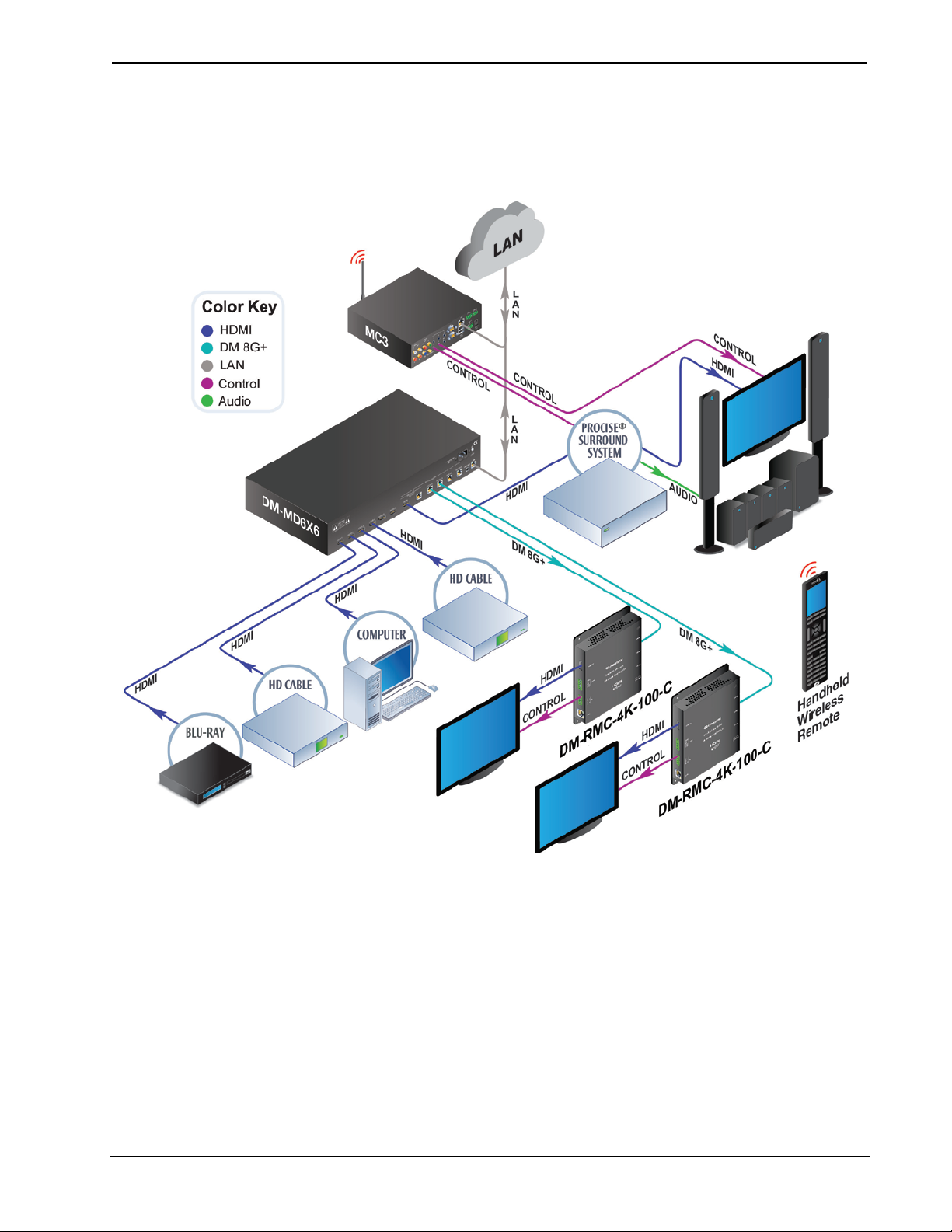
Applications
The diagram below shows a DM-MD6X6 in a typical application.
DM-MD6X6 in a Typical Application
Installation & Operation Guide – DOC. 7196B DigitalMedia Distribution Center: DM-MD6X4/DM-MD6X6 • 5
Page 10

DigitalMedia Distribution Center Crestron DM-MD6X4/DM-MD6X6
Internal Block Diagrams
The following diagrams represent the switching abilities of the DM-MD6X4 and
DM-MD6X6.
Internal Block Diagram of the DM-MD6X4
Internal Block Diagram of the DM-MD6X6
6 • DigitalMedia Distribution Center: DM-MD6X4/DM-MD6X6 Installation & Operation Guide – DOC. 7196B
Page 11

Crestron DM-MD6X4/DM-MD6X6 DigitalMedia Distribution Center
Specifications
Specifications for the DM-MD6X4 and DM-MD6X6 are listed in the below table.
DM-MD6X4/DM-MD6X6 Specifications
SPECIFICATION DETAILS
Video
Switcher
Input Sign al Types HDMI, DVI1, DisplayPort Multimode1
Output Signal Types
Formats
Input Reso lutions
Progressive
Interlaced
6X4 (DM-MD6X4) or 6x6 (DM-MD6X6)
digital matrix switch, Crestron
QuickSwitch HD
HDMI, DVI
one CAT5e or better twisted pair cop per
wire)2, HDBaseT2
DM 8G+, HDBaseT, HDMI with Deep
Color and 3D; DVI; HDCP content
protection support
640 x 480 @ 60 Hz
720 x 480 @ 60 Hz (480p)
720 x 576 @ 50 Hz (576p)
800 x 600 @ 60 Hz
848 x 480 @ 60 Hz
852 x 480 @ 60 Hz
854 x 480 @ 60 Hz
1024 x 768 @ 60 Hz
1024 x 852 @ 60 Hz
1024 x 1024 @ 60 Hz
1280 x 720 @ 50 Hz (720p50)
1280 x 720 @ 60 Hz (720p60)
1280 x 768 @ 60 Hz
1280 x 800 @ 60 Hz
1280 x 960 @ 60 Hz
1280 x 1024 @ 60 Hz
1360 x 768 @ 60 Hz
1365 x 1024 @ 60 Hz
1366 x 768 @ 60 Hz
1400 x 1050 @ 60 Hz
1440 x 900 @ 60 Hz
1600 x 900 @ 60 Hz
1600 x 1200 @ 60 Hz
1680 x 1050 @ 60 Hz
1920 x 1080 @ 24 Hz (1080p24)
1920 x 1080 @ 25 Hz (1080p25)
1920 x 1080 @ 50 Hz (1080p50)
1920 x 1080 @ 60 Hz (1080p60)
1920 x 1200 @ 60 Hz
2048 x 1080 @ 24 Hz
2048 x 1152 @ 60 Hz
plus any other resolution allowed by
HDMI up to 165 MHz pixel clock
720 x 480 @ 30 Hz (480i)
720 x 576 @ 25 Hz (576i)
1920 x 1080 @ 25 Hz (1080i25)
1920 x 1080 @ 30 Hz (1080i30)
plus any other resolution allowed by
HDMI up to 165 MHz pixel clock
1
, DM 8G+ (DigitalMedia over
(Continued on following page)
Installation & Operation Guide – DOC. 7196B DigitalMedia Distribution Center: DM-MD6X4/DM-MD6X6 • 7
Page 12

DigitalMedia Distribution Center Crestron DM-MD6X4/DM-MD6X6
DM-MD6X4/DM-MD6X6 Specifications (Continued)
SPECIFICATION DETAILS
Video (Continued)
Output Resolutions Matched to inputs
Audio
Switcher
Input Sign al Types HDMI, DisplayPort Multimode1
Output Signal Types HDMI, DM 8G+. HDBaseT
Formats
Communications
DigitalMedia
Ethernet
HDBaseT HDCP3, EDID3, PoH, Ethernet
HDMI HDCP3, EDID3, CEC3
USB
Power Requirements
Main Po wer
Power over DM (PoDM)
Power over HDBaseT (PoH)
Environmental
Temperature 32 ºF to 104 ºF (0 ºC to 40 ºC)
Humidity 10% to 90% RH (non-condensing)
Heat Dissi pation 310 BTU/hr
6x4 (DM-MD6X4) or 6x6 (DM-MD6X6)
digital matrix switch, audio-follow-video
Dolby Digital® audio, Dolby Digital EX,
Dolby Digital Plus, Dolby TrueHD,
DTS® audio, DTS ES, DTS 96/24, DTS
HD High Res, DTS HD Master Audio, up
to 8ch PCM
DM 8G+, HDCP
Ethernet
10/100 Mbps, auto-switching,
auto-negotiating, auto-discovery, full/half
duplex, DHCP, Private Network Mode
Supports signal extension and routing of
USB HID class devices, expandable t o
support almost any USB 1.1 or 2.0 device
using Crestron USB-EXT-DM USB over
Ethernet extenders
computer console (setup)
2 Amps @ 100-240 Volts AC, 50/60 Hz
PoDM PSE (Power Sourcing Equipment),
each DM 8G+ port supplies up to 15.4
Watts (Class 0–3) to one PoDM Powered
Device
PoH PSE (Power Sourcing Equipment),
each DM 8G+ port supplies up to 15.4
Watts (Class 0–3) to one PoDM Powered
Device
3
, EDID3, CEC3, PoDM,
4
; USB device port for
(Continued on following page)
8 • DigitalMedia Distribution Center: DM-MD6X4/DM-MD6X6 Installation & Operation Guide – DOC. 7196B
Page 13

Crestron DM-MD6X4/DM-MD6X6 DigitalMedia Distribution Center
DM-MD6X4/DM-MD6X6 Specifications (Continued)
SPECIFICATION DETAILS
Enclosure
Chassis
Faceplate
Mounting
Dimensions
Height 3.47 in (89 mm) without feet
Width
Depth 13.38 in (340 mm)
Weight 12.0 lb (5.5 kg)
Available Accessories
CBL Series Crestron Certified Interface C ables
DM-8G-CONN DigitalMedia 8G Cable Connectors
DM-8G-CONN-WG
DM-8G-CRIMP Crimping Tool for DM-8G-CONN
DM-8G-CRIMP-WG Crimping Tool for DM-8G-CONN-WG
DM-CBL-8G DigitalMedia 8G Cable
DM-RMC-200-C
DM-RMC-4K-100-C
DM-RMC-4K-SCALER-C
DM-RMC-4K-SCALER-C-DSP
DM-RMC-SCALER-C
HD-SCALER-HD-E
HD-SCALER-VGA-E
MP-WP(I) Series
USB-EXT DM USB over Ethernet Extender with Routing
1. HDMI requires an appropriate adapter or interface cable to accommodate a DVI or DisplayPort
Multimode signal. Crestron CBL-HD-DVI interface cables are sold separately.
2. For DM 8G+ or HDBaseT wiring up to 330 feet (100 meters) between devices, use Crestron
DM-CBL-8G DigitalMedia 8G cable or generic CAT5e (or better) UTP or STP. Shielded cable and
connectors are recommended to safeguard against unpredictable environmental electrical noise that
may impact performance at resolutions above 1080p. For complete system design guidelines, refer to
the Crestron DigitalMedia Design Guide (Doc. 4546). All wire and cables are sold separately.
3. The DM-RM6X4 and DM-RM6X6 support management of HDCP and EDID; the devices also
support management of CEC between the connected HDMI devices and a control system.
4. USB-EXT DM USB over Ethernet extender modules are sold separately. Refer to the USB-EXT-DM
spec sheet on the product webpage for more information.
Metal with black finish, vented sides,
fan cooled
Metal, black finish with polycarbonate
label overlay
Freestanding or 2U 19-inch rack
mountable (adhesive feet and rack ears
included)
17.03 in (433 mm) without ears,
19.00 in (483 mm) with ears
DigitalMedia 8G Cable Connectors with
Wire Guide
DigitalMedia 8G+ Receiver & Room
Controller 200
4K DigitalMedia 8G+ Receiver & Room
Controller 100
4K DigitalMedia 8G+ Receiver & Room
Controller with Scaler
4K DigitalMedia 8G+ Receiver & Room
Controller with Scaler
DigitalMedia 8G+ Receiver & Room
Controller with Scaler & Downmixing
High-Definition Video Scaler, HDMI In
and HDMI Out
High Definition Video Scaler, VGA In,
HDMI Out
Media Presentation Wall Plates (U.S. and
International Versions)
Installation & Operation Guide – DOC. 7196B DigitalMedia Distribution Center: DM-MD6X4/DM-MD6X6 • 9
Page 14

DigitalMedia Distribution Center Crestron DM-MD6X4/DM-MD6X6
Physical Description
This section provides information on the connections, c o ntrols, and indicators
available on the DM-MD6X4 and DM-MD6X6.
DM-MD6X4 Physical Views (Front and Rear)
DM-MD6X6 Physical Views (Front and Rear)
10 • DigitalMedia Distribution Center: DM-MD6X4/DM-MD6X6 Installation & Operation Guide – DOC. 7196B
Page 15

Crestron DM-MD6X4/DM-MD6X6 DigitalMedia Distribution Center
17.03 in
(433 mm)
13.00 in
(331 mm)
16.79 in
(427 mm)
0.35 in
(9 mm)
19.00 in
(483 mm)
18.31 in
(466 mm)
3.00 in
(77 mm)
3.47 in
(89 mm)
0.24 in
(7 mm)
DM-MD6X4/DM-MD6X6 Overall Dimensions (Top View)
DM-MD6X4/DM-MD6X6 Ov erall Dimensions (Front View, DM-MD6X6 Shown)
Installation & Operation Guide – DOC. 7196B DigitalMedia Distribution Center: DM-MD6X4/DM-MD6X6 • 11
Page 16

DigitalMedia Distribution Center Crestron DM-MD6X4/DM-MD6X6
1
54
3
2 6
7 8
9 10 11
12
14
15
13
9 10
11
12
14
15
13
1
543
2 6
7 8
DM-MD6X4 Connectors, Controls, and Indicators (Front and Rear Views)
DM-MD6X6 Connectors, Controls, and Indicators (Front and Rear Views)
12 • DigitalMedia Distribution Center: DM-MD6X4/DM-MD6X6 Installation & Operation Guide – DOC. 7196B
Page 17

Crestron DM-MD6X4/DM-MD6X6 DigitalMedia Distribution Center
Pin
4
Pin
1
Pin 3
Pin 2
2
Data -
3
Data +
4
Ground
Connectors, Controls, and Indicators
# CONNECTORS,
CONTROLS &
INDICATORS
1 HW-R Button
2
3
4
COMPUTER
Liquid Crystal Display
(LCD)
Navigation Pad
DESCRIPTION
(1) Recessed miniature push button for
hardware reset
(1) USB Type B female;
USB computer console port (setup only)
(6 foot [~1.8 meters] cable includ ed)
PIN DESCRIPTION
1 +5 VDC
(1) 16-bit TFT active matrix color LCD;
2 inch (52 mm) diagonal;
220 x 176 pixel resolution;
Displays setup menus, EDID and HDCP
details for source and destination
devices, audio/video signal information,
and other details;
Allows custom naming of inputs and
outputs
(1) 5-way navigation pad for menu
navigation and parameter adjust ment:
Up, Down, Left, and Right navigation
buttons;
Select button: Executes highlighted
menu item or value
5 HOME Button
(1) Push button, returns to the home
screen
6 BACK Button
(1) Push button, steps menu back one
menu level
INPUT Buttons and LEDs,
7
8
OUTPUT Buttons and
LEDs, 1–4/1–6
1–6
(6) Push buttons and green LEDs, sel ec t
input for routing
DM-MD6X4 (4) or DM-MD6X6 (6) push
buttons and green LEDs, select output
destination(s)
9
10
INPUT
HDMI 1 – HDMI 6
OUTPUT
HDMI 1
(6) 19-pin Type A HDMI female,
digital video/audio inputs;
Signal Types: HDMI, DVI, or DisplayPort
Multimode
1
(1) 19-pin Type A HDMI female,
digital video/audio output;
Signal Types: HDMI, DVI1
(Continued on following page)
Installation & Operation Guide – DOC. 7196B DigitalMedia Distribution Center: DM-MD6X4/DM-MD6X6 • 13
Page 18

DigitalMedia Distribution Center Crestron DM-MD6X4/DM-MD6X6
Green
LED
Amber
LED
Pin 8
Pin 1
Pin 2
Pin 3
Pin 1
Pin 4
1
+5 VDC
2
Data -
3
Data +
4
Ground
Green
LED
Amber
LED
Pin 8
Pin 1
PIN
SIGNAL
PIN
SIGNAL
1
TX + 5 N/C
2
TX - 6 RX - 3 RX + 7 N/C
4
N/C 8 N/C
Connectors, Controls, and Indicators (Continued)
# CONNECTORS,
CONTROLS &
INDICATORS
11
DM2 – DM4/DM2 – DM6
12
OUTPUT
USB HID
DESCRIPTION
DM-MD6X4 (3) or DM-MD6X6 (5)
2, 3
8-pin RJ-45 female, shielded, with two
LED indicators;
DM 8G+ outputs, HDBaseT compliant
PoDM and PoH PSE (Power Sourcing
Equipment) ports
Connects to DM 8G+ inputs of DM
receivers/room controllers or other DM
devices, or to an HDBaseT device, via
CAT5e (or better) or Crestron DM-CBL8G cable.5 Green LED indicates DM link
status; Solid amber LED indicates HD CP
video; Blinking amber LED indicat es nonHDCP video
(1) USB Type B female;
Supports signal extension and routing of
USB HID class devices, expandable t o
support almost any USB 1.1 or 2.0
device using Crestron USB-EXT-DM
USB over Ethernet extenders6
PIN DESCRIPTION
4
13
LAN
(1) 8-pin RJ-45 female, shielded, with
2
two LED indicators;
10BASE-T/100BASE-TX Ethernet port,
Green LED indicates Ethernet link status;
Amber LED indicates Ethernet activity
14
G
(1) 6-32 screw, chassis ground lug
15
100–240V ~ 2.0A MAX
50/60 Hz
(1) IEC C14 male chassis plug, main
power input:
Mates with removable power cord
(included)
1. HDMI requires an appropriate adapter or interface cable to accommodate a DVI or DisplayPort
Multimode signal. Crestron CBL-HD-DVI interface cables are sold separately.
2. To determine which is pin 1 on the cable, hold the cable so the end of the eight pin modular jack is
facing away from you, with the clip down and copper side up. Pin 1 is on the far left.
3. A DM output port consists of an RJ-45 connector. Refer to the table on the following page for the
connector pinouts.
14 • DigitalMedia Distribution Center: DM-MD6X4/DM-MD6X6 Installation & Operation Guide – DOC. 7196B
Page 19

Crestron DM-MD6X4/DM-MD6X6 DigitalMedia Distribution Center
1 8
DM Output Connector Pinouts
PIN # WIRE COLOR PIN # WIRE COLOR
1 Orange/White 5 Blue/White
2 Orange 6 Green
3 Green/White 7 Brown/White
4 Blue 8 Brown
4. Any wiring that is connected to a PoDM or PoH PSH port is for intra-building use only and should
not be connected to a line that runs outside of the building in which the PSE is located.
5. For DM 8G+ or HDBaseT wiring up to 330 feet (100 meters) between devices, use Crestron
DM-CBL-8G DigitalMedia 8G cable or generic CAT5e (or better) UTP or STP. Shielded cable and
connectors are recommended to safeguard against unpredictable environmental electrical noise that
may impact performance at resolutions above 1080p. For complete system design guidelines, refer to
the Crestron DigitalMedia Design Guide (Doc. 4546). All wire and cables are sold separately.
6. USB-EXT DM USB over Ethernet extender modules are sold separately. Refer to the
USB-EXT-DM spec sheet on the product webpage for more information.
Installation & Operation Guide – DOC. 7196B DigitalMedia Distribution Center: DM-MD6X4/DM-MD6 X6 • 15
Page 20

DigitalMedia Distribution Center Crestron DM-MD6X4/DM-MD6X6
receivers/room controllers.
Setup
Network Wiring
When wiring the DM network, consider the following:
• Use Crestron Certified Wire.
• Use Crestron power supplies for Crestron equipment.
CAUTION: Failure to use Crestron power supplies could cause equipment
damage or void the Crestron warranty.
• Provide sufficient power to the system.
• For DM 8G+ or HDBaseT wiring up to 330 feet (100 meters) between
devices, use Crestron DM-CBL-8G DigitalMedia 8G cable or generic
CAT5e (or better) UT P or ST P. Shielded cable and connector s are
recommended to safeguard against unpredictable environmental electrical
noise that may impact performance at resolutions above 1080p. For
complete system design guidelines, refer to the Crestron DigitalMedia
Design Guide (Doc. 4546). All wire and cables are sold separately.
IP Configuration
The DM-MD6X4 and DM-MD6X6 also use high-speed Ethernet for
communications between the device and a control system, computer, media server
and other IP-based devices. For information related to Ethernet connectivity using
DigitalMedia devices, refer to the IP Considerations Guidelines for the IT
Professional Design Guide (Doc. 4579) at www.crestron.com/manuals.
Ethernet Setup
The DM-MD6X4 and DM-MD6X6 are designed to control the Ethernet settings of
DM endpoints in order to reduce the amount of IP configuration necessary and make
the DM endpoints swappable without reconfiguratio n. For the DM-MD6X4 and
DM-MD6X6, DM endpoints consist of DM 8G+ receivers/room controllers such as
the DM-RMC-SCALER-C, DM-RMC-200-C, DM-RMC-4K-SCALER-C, and
DM-RMC-4K-SCALER-C-DSP.
The DM-MD6X4 and DM-MD6X6 can operate in DHCP or Static IP Address mode.
The DM-MD6X4 and DM-MD6X6 also control th e IP addre s sing information of
DM 8G+ receivers/room controllers. When the DM -MD6X4 and DM-MD6X6
operate in DHCP mode, the DM 8G+ receivers/room controllers also operate in
DHCP mode. When the DM-MD6X4 and DM-MD6X6 operate in Static IP Address
mode, the DM 8G+ receivers/room controllers receive a static IP configuration
equivalent to the DM-MD6X4 or DM-MD6X6 IP address plus their slot number.
This configuration is sent when the DM-MD6X4 or DM-MD6X6 starts up. Refer to
the following table for information about static IP address configuration of DM 8G+
16 • DigitalMedia Distribution Center: DM-MD6X4/DM-MD6X6 Installation & Operation Guide – DOC. 7196B
Page 21

Crestron DM-MD6X4/DM-MD6X6 DigitalMedia Distribution Center
For more information, refer to “IP Table Options” on page 33.
be avoided on all sides of the unit.
Static IP Address Configuration of DM 8G+ Receivers/Room Controllers
IP Table Setup
DM-MD6X4/DM-MD6X6
OUTPUT NUMBER
1 N/A (HDMI only)
2 Base + 18
3 Base + 19
4 Base + 20
5 (DM-MD6X6 only) Base + 21
6 (DM-MD6X6 only) Base + 22
* Base equals the static IP address of the DM-MD6X4 or DM-MD6X6.
DigitalMedia 8G+ devices that receive their IP address configuration via the
DM-MD6X4 and DM-MD6X6 can also receive their IP table configuration from the
DM-MD6X4 and DM-MD6X6.
DM 8G+ RECEIVER/ROOM
CONTROLLER IP ADDRESS*
Identity Code
The IP ID can be set from the front panel or in the IP table of the DM-MD6X4 or
DM-MD6X6 using Crestron Toolbox. For information on setting the IP ID from the
front panel, refer to the discussion of the IP ID parameter at the bottom of page 28.
For information on setting an IP table, refer to the embedded Crestron Toolbox he lp
file. The IP IDs of multiple DM-MD6X4 or DM-MD6X6 units in the same syste m
must be unique.
Ventilation
When setting the IP ID, con sider the following:
• The IP ID of each unit must match an IP ID specified in the SIMPL
Windows program.
• Each device using IP to communicate with a control system must have a
unique IP ID.
Installation
The DM-MD6X4 and DM-MD6X6 should be used in a well-ventilated area. The
venting holes should not be o bs t ructed under any circumstances.
To prevent overheating, do not operate this product in an area that exceeds the
environmental temperature range listed in the table of specifications. Consider using
forced air ventilation and/or incrementing the spacing between units to reduce
overheating. Consideration must be given if installed in a closed or multi unit rack
assembly since the operating ambient temperature of the environment may be greater
than the room ambient temperature. Contact with thermal insulating materials should
Installation & Operation Guide – DOC. 7196B DigitalMedia Distribution Center: DM-MD6X4/DM-MD6X6 • 17
Page 22

DigitalMedia Distribution Center Crestron DM-MD6X4/DM-MD6X6
attach the ears to the unit. The only tool required is a #1 or #2 Phillips screwdriver.
Cover
screws (6)
Rack Mounting
The DM-MD6X4 and DM-MD6X6 can be mounted in a r a c k or stacked with other
equipment. Two “ears” are provided with the unit so that it can be rack mounted.
These ears must be installed prior to mounting. Complete the following procedure to
WARNING: To prevent bodily injury when mounting or servicing this unit in a
rack, take special precautions to ensure that the system remains stable. The following
guidelines are provided to ensure your safety:
• When mounting this unit in a partially filled rack, load the rack from the
bottom to the top with the heaviest component at the bottom of the rack.
• If the rack is provided with stabilizing devices, install the stabilizers before
mounting or servicing the unit in the rack.
NOTE: If rack mounting is not required, rubber feet are provided for tabletop
mounting or stacking. A pply the feet near the corner edges on the underside of the
unit.
NOTE: Reliable earthing of rack-mounted equipment should be maintained.
Particular attenti on s h ould be given to supply connections other than direct
connections to the branch circuit (such as the use of power strips).
To install the ears, use the following procedu re :
1. Locate the screws that secure each side of the top cover. Using a #1 or #2
Phillips screwdriver, remove the three screws closest to the front panel from
one side of the unit. Refer to the diagram following step 3 for a detailed
view.
2. Position a rack ear so that its mounting holes align with the holes vacated
by the screws in step 1.
3. Secure the ear to the unit with the three screws removed in step 1 as shown
in the following diagram.
Ear Attachment for Rack Mounting
4. Repeat the above procedure (steps 1 through 3) to attach the remaining ear
to the opposite side.
18 • DigitalMedia Distribution Center: DM-MD6X4/DM-MD6X6 Installation & Operation Guide – DOC. 7196B
Page 23

Crestron DM-MD6X4/DM-MD6X6 DigitalMedia Distribution Center
procedure. Refer to the following illustration for placement of the feet.
Place Feet in Corners
COMPUTER:
To computer
console
COMPUTER:
To computer
console
Stacking
Four “feet” are provided with the DM-MD6X4 and DM-MD6X6 so that if the unit is
not rack mounted, the rubber feet can provide stability when the unit is placed on a
flat surface or when it is stacked. These feet should be attached prior to the hookup
Foot Placement for the DM-MD6X4/DM-MD6X6
NOTE: No more than two DM-MD6X4 or DM-MD6X6 units should be stacked.
Hardware Hookup
Make the necessary connections as called out in the following illustrations. Refer to
“Network Wiring” on page 16. Apply power after all connections have been made.
Hardware Connections for the DM-MD6X4 (Front)
Hardware Connections for the DM-MD6X6 (Front)
Installation & Operation Guide – DOC. 7196B DigitalMedia Distribution Center: DM-MD6X4/DM-MD6X6 • 19
Page 24

DigitalMedia Distribution Center Crestron DM-MD6X4/DM-MD6X6
HDMI 1–6:
From HDMI
source
HDMI 1:
T
o HDMI
display/receiver
DM 2–4:
T
o DM receiver
or other DM or
HDBaseT device
USB HID:
T
o local
USB host
LAN:
10BASE-T/
100BASE-TX
Ethernet to LAN
100–240 V
(~2.0
A max)
50/60 Hz:
From
ac power outlet Ground
HDMI 1–6:
From HDMI
source
HDMI 1:
T
o HDMI
display/receiver
DM 2–6:
T
o DM receiver
or other DM or
HDBase
T device
USB HID:
T
o local
USB host
LAN:
10BASE-T/
100BASE-TX
Ethernet to LAN
100–240 V
(~2.0
A
max)
50/60 Hz:
From
ac power outlet
Ground
Hardware Connections for the DM-MD6X4 (Rear)
Hardware Connections for the DM-MD6X6 (Rear)
NOTE: Ensure that the unit is properly grounded by connecting the chassis ground
lug to an earth ground (building steel).
NOTE: To prevent overheating, do not operate this product in an area that exceeds
the environmental temperature range listed in the table of specifications.
NOTE: For DM 8G+ or HDBaseT wiring up to 330 feet (100 meters) between
devices, use Crestron DM-CBL-8G DigitalMedia 8G cable or generic CAT5e (or
better) UTP or STP. Shielded cable and connectors are recommended to safeguard
against unpredictable environmental electrical noise that may impact performance at
resolutions above 1080p. For complete system design guidelines, refer to the
Crestron DigitalMedia Design Guide (Doc. 4546). All wire and cables are sold
separately.
20 • DigitalMedia Distribution Center: DM-MD6X4/DM-MD6X6 Installation & Operation Guide – DOC. 7196B
Page 25

Crestron DM-MD6X4/DM-MD6X6 DigitalMedia Distribution Center
Configuration and Status
When the DM-MD6X4 and DM-MD6X6 is in Installer mode, use the front panel to
configure the device and to view status information.
NOTE: Crestron Toolbox can also be used to configure the DM-MD6X4
and DM-MD6X6 and to view status information. For more information, refer to the
embedded Crestron Toolbox help file.
Accessing Installer Mode
When the DM-MD6X4 or DM-MD6X6 is in Installer mode, use the front panel to
configure the device and to view status information.
To access Installer mode, use the following pr ocedure:
1. Ensure that the home screen is displayed on the front panel LCD screen. If
it is not displayed, press the HOME button.
The home screen is shown below.
Home Screen (DM-MD6X6 Shown)
NOTE: After 30 seconds of inactivity, the DM-MD6X4 and DM-MD6X6
time out and return to the home screen while dimming the LCD.
2. Press the BACK button.
The Installer password screen appears as shown below.
Installer Password Screen
The first digit is enclosed in brackets when the Installer password screen
appears.
Installation & Operation Guide – DOC. 7196B DigitalMedia Distribution Center: DM-MD6X4/DM-MD6X6 • 21
Page 26

DigitalMedia Distribution Center Crestron DM-MD6X4/DM-MD6X6
3. Enter the four-digit pa ss word (the default password is "1234"). To enter a
digit, do either of the following:
• If the digit ranges from 1–6, press the appropriate INPUT or OUTPUT
button that corresponds to the digit to be entered. After a digit is
entered, brackets move to the next digit to be entered.
• If the digit is 0 or ranges from 7–9, press the Up or Down navigation
button as necessary until the desired digit appears between the brackets,
and then press the Select button. Brackets move to the next digit to be
entered.
NOTE: If necessary, the Left or Right navigation butt on can be used to
navigate to a digit in the password.
After the fourth digit is correctly entered, the Installer menu screen appears
as shown below.
NOTE: The password can be changed or disabled. For information on
changing or disabling the password, refer to the discussion of the Password
parameter in the “Control” section on page 30
.
Installer Menu
As shown above, the Installer menu allows configuration of the following
items:
• Inputs: Configures the DM-MD6X4 or DM-MD6X6 inputs and
provides status information about the inputs
• Outputs: Configures the DM-MD6X4 or DM-MD6X6 outputs
and provides status information about the outputs
• Network: Configures the Ethernet and control system connection
settings and provides network status information
• Control: Configures the various front panel controls, allows
editing of the Installer password, allows re s toring to factorydefault settings, and provides firmware version information.
22 • DigitalMedia Distribution Center: DM-MD6X4/DM-MD6X6 Installation & Operation Guide – DOC. 7196B
Page 27

Crestron DM-MD6X4/DM-MD6X6 DigitalMedia Distribution Center
Inputs
A name can be configured for each input. In addition, Video EDID and Audio EDID
information, which is presented to the upstream source device, can be viewed.
(EDID configuration is set using the DMTool in Crestron Toolbox.)
To configure an input or to view information about the input, use the following
procedure:
1. Access the Installer menu screen. (Refer to “Accessing Installer Mode” on
page 21.)
NOTE: If the DM-MD6X4 or DM-MD6X6 is already in Installer mode,
press the BACK button on the front panel until the Installer menu appears.
2. Navigate to Inputs if it is not already highlighted, and then press the Select
button on the navigat ion pad.
The Input submenu appears as shown below for the currently selected
input. (Note that the LED of the currently selected input is lit.)
Input Submenu (Input 1 Shown)
The name of the input is shown at the top of the Input submenu. For input
1, the default name is Input 1; for input 2, the name is Input 2; and so on.
3. Select the desired input by pressing the appropriate INPUT button,
numbered from 1 to 6, on the front panel.
The LED of the selected input lights, and the name of the input appears at
the top of the Input submenu.
4. Perform any of the followi ng using the navigation pad:
• Change the name of the input as follows:
a. Navigate to Name if it is not already highlighted, and then press
the Select button.
A scrollable list of predefined source names appears for the input.
b. Navigate to the desired source name in the list, and then press the
Select button to confirm the selection.
The selected name now appears at the top of the Input submenu
for the selected input.
• View Video EDID information. To do so, navigat e t o Video EDID on
the Input submenu and then press the Select button.
• View Audio EDID information. To do so, navigate to Audio EDID on
the Input submenu and then press the Select button.
Installation & Operation Guide – DOC. 7196B DigitalMedia Distribution Center: DM-MD6X4/DM-MD6X6 • 23
Page 28

DigitalMedia Distribution Center Crestron DM-MD6X4/DM-MD6X6
Outputs
A name can be configured for each output. In addition, information about the
connected DM 8G+ receiver/room controller can be viewed, as well as Video EDID
and Audio EDID information. The EDID information is read from the downstream
device (such as a display).
To configure an output or to view information about the output, use the following
procedure:
1. Access the Installer menu screen. (Refer to “Accessing Installer Mode” on
page 21.)
NOTE: If the DM-MD6X4 or DM-MD6X6 is already in Installer mode,
press the BACK button on the front panel until the Installer menu appears.
2. Navigate to Outputs, and then press the Select button on the navigation
pad.
The Output submenu appears as shown below for the currently selected
output. (The LED of the currently selected output is lit.)
Output Submenu (Output 1 Shown)
The name of the output is shown at the top of the Output submenu. For
output 1, the default name is Output 1; for output 2, the name is Output 2;
and so on.
3. Select the desired output by pressing the appr opriate OUTPUT button
numbered from 1 to 4 (DM-MD6X4) or from 1 to 6 (DM-MD6X6).
The LED of the selected output lights, and the name of the output appears at
the top of the Output submenu.
4. Perform any of the following using the navigation pa d:
• Change the name of the output as follows:
a. Navigate to Name if it is not already highlighted, and then press
the Select button.
A scrollable list of predefined room names appears for the output.
b. Navigate to the desired room name in the list, and then press the
Select button.
The selected name appears at the top of the Output submenu for
the selected output.
24 • DigitalMedia Distribution Center: DM-MD6X4/DM-MD6X6 Installation & Operation Guide – DOC. 7196B
Page 29

Crestron DM-MD6X4/DM-MD6X6 DigitalMedia Distribution Center
• For outputs 2–4 (DM-MD6X4) and outputs 2–6 (DM-MD6X6), view
information such as the firmware version and the IP address of the
connected DM 8G+ receiver/room controller. To do so, navigate to the
model name of the connected DM 8G+ device on the Output submenu,
and then press the Select button.
NOTE: For output 1, HDMI is always displayed on the Output
submenu. Pressing the Select button displays HDMI again.
• View Video EDID information. To do so, n a vigate to Video EDID on
the Output submenu and then press the Select button.
• View Audio EDID information. To do so, navigate to Audio EDID on
the Output submenu and then press the Select button.
Network
Ethernet settings can be configured for the DM-MD6X4 and DM-MD6X6 by
configuring network parameters. Network parameters include the following:
• IP Address (applicable only if DHCP [Dynamic Host Configuration
Protocol] is disabled): Allows adding or editing a static IP addres
• Subnet Mask (applicable only if DHCP is disabled): Allows adding or
editing a subnet mask address
• Default Router (applicable only if DHCP is disabled): Allows adding or
editing a default router address
• DHCP: Allows DHCP to be enabled or disabled
NOTE: DHCP is enabled by default.
• Control System: (the IP ID of the DM-MD6X4 or DM-MD6X6 and the IP
address of the control system): Allows adding and editing control system
parameters
In addition, the network status can also be viewed.
To view network status or to c onfigure network parameters, use the following
procedure:
NOTE: Changes to network parameter settings take effect when the
DM-MD6X4 or DM-MD6X6 exits Installer mode and the device automatically
reboots. A message appears on the LCD screen indicating that the device is
rebooting. For information about exiting Installer mode, refer to “
Mode” on page 31
1. Access the Installer menu screen. (Refer to “Accessing Installer Mode” on
page 21.)
.
Exiting Installer
NOTE: If the DM-MD6X4 or DM-MD6X6 is already in Installer mode,
press the BACK button on the front panel until the Installer menu appears.
2. Navigate to Network, and then press the Select button on the navigation
pad.
The Network submenu appears as shown on the following page. The
submenu is scrollable as indicated by the bar on the right side of the screen.
Installation & Operation Guide – DOC. 7196B DigitalMedia Distribution Center: DM-MD6X4/DM-MD6X6 • 25
Page 30

DigitalMedia Distribution Center Crestron DM-MD6X4/DM-MD6X6
Network Submenu
3. Perform any of the following as required using the navigation pad:
• View the network status. To do so, navigate to Status if it is not
already highlighted, and then press the Select button. Basic and
advanced status information can be viewed.
• If DHCP is disabled, configure the following parameters. To do so,
navigate to the parameter and then press the Select button.
o Address: Accesses the IP Address configuration scree n, which
allows a unique static IP address to be entered
IP Address Configuration Screen
As shown above, the first octet of the IP address is enclosed in
brackets when the IP Address configuration screen appears.
NOTE: IP Address is applicable only if DHCP is set to Off in the
Network submenu. If DHCP is set to On, the following message is
displayed at the bottom of the IP Address configuration screen:
*DHCP ON: Address invalid
Enter a static IP address using the navigation pad. For each octet in
the IP address, press the Up or Down navigation button until the
desired number appears, and then press the Select button.
NOTE: If necessary, the Left or Right navigation button can be
used to navigate to an octet in the IP address.
The screen returns to the Network submenu after the last octet is
selected.
o Subnet Mask: Accesses the Subnet Mask configuration screen,
which allows the address of the subnet mask that is set on the
network to be entered
26 • DigitalMedia Distribution Center: DM-MD6X4/DM-MD6X6 Installation & Operation Guide – DOC. 7196B
Page 31

Crestron DM-MD6X4/DM-MD6X6 DigitalMedia Distribution Center
Subnet Mask Configuration Screen
As shown above, the first octet of the subnet mask is enclosed in
brackets when the Subnet Mask configuration screen appears.
NOTE: Subnet Mask is applicable only if DHCP is set to Off in
the Network submenu. If DHCP is set to On, the following
message is displayed at the bottom of the Subnet Mask
configuration screen:
*DHCP ON: Address invalid
Enter the subnet mask using the navigation pad. For each octet in
the subnet mask, press the Up or Down navigation button until the
desired number appears, and then press the Select button.
NOTE: A class C network allows up to 255 devices to
communicate without a router and has a subnet mask of
255.255.255.0. A class B network allows up to 65 ,535 devices to
communicate without a router and has a subnet mask of
255.255.0.0.
NOTE: If necessary, the Left or Right navigation button can be
used to navigate to an octet in the subnet mask.
The screen returns to the Network submenu after the last octet is
selected.
o Default Router: Accesses the Default Router configuration
screen, which allows the IP address of the network’s device
(usually a router) to be entered
The default router IP address enables communication between the
network and the Internet.
Default Router Configuration Screen
Installation & Operation Guide – DOC. 7196B DigitalMedia Distribution Center: DM-MD6X4/DM-MD6X6 • 27
Page 32

DigitalMedia Distribution Center Crestron DM-MD6X4/DM-MD6X6
As shown on the prior page, the first octet of the default router IP
address is enclosed in brackets when the Default Router
configuration screen appears.
NOTE: Default Router is applicable only if DHCP is set to Off
in the Network submenu. If DHCP is set to On, the following
message is displayed at the bottom of the Default Rou te r
configuration screen:
*DHCP ON: Address invalid
Enter the default router IP addres s us i ng the navigation pad. For
each octet in the IP address, press the Up or Down navigation
button until the desired number appears, and then press the Select
button.
NOTE: If necessary, the Left or Right navigation button can be
used to navigate to an octet in the default router IP address.
The screen returns to the Network submenu after the last octet is
selected.
• Enable or disable DHCP:
a. Navigate to DHCP in the Network submenu, and then press the
Select button.
The DHCP configuration screen appears, allowing DHCP to be set
to On (the default setting) or Off.
NOTE: An asterisk indicates the current setting.
NOTE: When set to On, the IP address is automatically assigned
by a DHCP server on the LAN for a predetermined period of time.
b. Navigate to the desired setting, and then press the Select button.
The screen returns to the Network submenu.
• Configure control system parameters:
a. Navigate to Control System in the Network submenu, and then
press the Select button.
The Control System submenu appears, allowing configuration of
IP ID and IP Address settings.
b. Navigate to the desired parameter, and then press the Select button:
o IP ID: Accesses the IP ID configuration screen, which allows
the IP ID of the DM-MD6X4 or DM-MD6X6 to be selected.
The value ranges from 03 (default setting) to FE. The value
selected must match the IP ID specified in SIMPL Windows
and the value on the control system’s IP table for the
DM-MD6X4 or DM-MD6X6.
Specify the IP ID by pressing the Up o r Down button until the
desired value appears, and then press the Select button.
28 • DigitalMedia Distribution Center: DM-MD6X4/DM-MD6X6 Installation & Operation Guide – DOC. 7196B
Page 33

Crestron DM-MD6X4/DM-MD6X6 DigitalMedia Distribution Center
The screen returns to the Control System submenu.
o IP Address: Accesses the Ctrl Sys IP Addr configuration
screen, which allows the IP address of the control system to be
entered.
Enter the control system IP address using the navigation pad.
For each octet in the IP address, press the Up or Down
navigation button until the desired number appears, and then
press the Select button.
NOTE: If necessary, the Left or Right navigation button can
be used to navigate to an octet in the control system IP
address.
The screen returns to the Control System submenu after the
last octet is selected.
Control
The following control para meters can be configured:
• Backlight: Allows the brightness of the front panel LCD screen to be
adjusted
• Password: Allow s the Installer password to be changed or disabled
• Front Panel:Lock: Prevents or allows changes to signal routings
• Restore Defaults: Restores the device to factory settings
In addition, firmware version information about the DM-MD6X4 or DM-MD6X6
and connected DM 8G+ receivers/room controllers can be viewed.
To configure control parameters or to view firmware version information, use the
following procedure:
1. Access the Installer menu screen. (Refer to “Accessing Installer Mode” on
page 21).
NOTE: If the DM-MD6X4 or DM-MD6X6 is already in Installer mode,
press the BACK button on the front panel until the Installer menu appears.
2. Navigate to Control and then press the Select button on the navigation pad.
The Control submenu appears as shown below.
Control Submenu
Installation & Operation Guide – DOC. 7196B DigitalMedia Distribution Center: DM-MD6X4/DM-MD6X6 • 29
Page 34

DigitalMedia Distribution Center Crestron DM-MD6X4/DM-MD6X6
3. Perform any of the followi ng using the navigation pad:
• Adjust the brightness of the LCD as follows :
a. Navigate to Backlight if it is not already highlighted, and then
press the Select button.
The Backlight configuration screen appears, which allows the
brightness of the display to be set to Bright (the default setting) or
Dim.
b. Navigate to the desired setting, and then press the Select button.
The screen returns to the Control submenu.
• Change or disable the Installer password as follows:
a. Navigate to Password and then press the Select button.
The Password configuration screen appears.
b. Enter the desired four-digit password. To enter a digit, do either of
the following:
o If the digit ranges from 1–6, press the corresponding
INPUT or OUTPUT button.
o If the digit is 0 or ranges from 7–9, press the Up or Down
navigation button as necessary until the desired digit
appears between the brackets, and then press the Select
button.
NOTE: Setting the password to "0000" disables
password protection.
NOTE: If necessary, the Left or Right navigation button
can be used to navigate to a digit in the password.
After the fourth digit is entered, the screen returns to the Control
submenu.
• Prevent or allow changes to signal routings as follows:
a. Navigate to Front Panel Lock and then press the Select button.
The Front Panel Lock configuration screen appears, allowing
Front Panel Lock to be set to On or Off (the default setting).
NOTE: An asterisk indicates the current setting.
NOTE: When set to On, changes cannot be made to signal
routings as described in the “Operation” section on page 39
.
b. Navigate to the desired setting, and then press the Select button.
The screen returns to the Control submenu.
30 • DigitalMedia Distribution Center: DM-MD6X4/DM-MD6X6 Installation & Operation Guide – DOC. 7196B
Page 35

Crestron DM-MD6X4/DM-MD6X6 DigitalMedia Distribution Center
• Restore the DM-MD6X4 or DM-MD6X6 to its factory settings as
follows:
a. Navigate to Restore Defaults and then press the Select button.
The Restore Defaults configuration screen appears.
b. Press the Down button on the navigation pad to highlight Yes, and
then press the Select button.
A prompt appears asking you whether you are sure you want to
restore the default settings.
c. Select Yes to restore the default settings or No to cancel.
The screen returns to the Control submenu.
• View firmware information about the DM-MD6X4 or DM-MD6X6
and connected DM 8G+ receivers/room controllers. To do so, navigate
to About and then press the Select button.
Exiting Installer Mode
To exit Installer mode, return to the home scre e n by pr e ss ing the HOME button.
NOTE: The home screen can also be accessed by pressing the BACK button as
necessary or by allowing the DM-MD6X4 or DM-MD6X6 to time out after
30 seconds of inactivity.
Installation & Operation Guide – DOC. 7196B DigitalMedia Distribution Center: DM-MD6X4/DM-MD6X6 • 31
Page 36

DigitalMedia Distribution Center Crestron DM-MD6X4/DM-MD6X6
system by selecting hardware from the Device Library.
Programming Software
Have a question or comment about Crestron software?
Answers to frequently asked questions (FAQs) can be viewed in the Online Help
section of the Crestron website. To post a question or to view questions that have
been submitted to Crestron’s True Blue Support, log in at
http://www.crestron.com/support. First-time users will need to establish a user
account.
Earliest Version Software Requirements for the PC
NOTE: Crestron recommends using the latest software to take advantage of the
most recently released features. The latest software is available from the Crestron
website at
Crestron provides an assortment of Windows software-based tools to develop a
customized system. Use SystemBuilder™ software or SIMPL Windows to create a
program to control the DM-MD6X4 or DM-MD6X6.
http://www.crestron.com/software.
Configuration Manager
Programming with SystemBuilder
SystemBuilder is a comprehensive programming environment. Appropriate for most
systems, it can quickly and easily generate a complete working program including
both control processor logic and touch screen graphics.
Programming with SIMPL Windows
SIMPL Windows is Crestron’s premier software for programming Crestron
control systems. It is organized into two separate but equally important “Managers”:
Configuration and Program.
Configuration Manager is the view where programmers “build” a Crestron control
1. To incorporate a DM-MD6X4 or DM-MD6X6 into the system, drag the
desired device from the DigitalMedia > DM Midpoints fol der o f the
Device Library and drop it in the System Views. (Refer to the image on
the following page.)
Locating the DM-MD6X4/DM-MD6X6 in the Device Library
32 • DigitalMedia Distribution Center: DM-MD6X4/DM-MD6X6 Installation & Operation Guide – DOC. 7196B
Page 37

Crestron DM-MD6X4/DM-MD6X6 DigitalMedia Distribution Center
application, add DM 8G+ devices as described below:
The system tree of the control system displays the device in the appropriate
slot with a default IP ID as shown in the illustration on the following page.
PRO3 Device, Slot 5 (DM-MD6X4 Shown)
2. If additional DM-MD6X4 or DM-MD6X6 devices are to be added, repeat
step 1 for each device. Each device is assigned a different IP ID number as
it is added.
3. If necessary, double-click a device to open the Device Settings dial og box
and change the IP ID as shown in the following illustration.
Device Settings Dialog Box (DM-MD6X4 Shown)
IP Table Options
Installation & Operation Guide – DOC. 7196B DigitalMedia Distribution Center: DM-MD6X4/DM-MD6X6 • 33
NOTE: The ID code specified in the SI M PL Windows program must
match the IP ID of each unit. Refer to “Identity Code” on page 17.
DigitalMedia 8G+ devices that receive their IP address configuration via the
DM-MD6X4 and DM-MD6X6 (for example, the DM-RMC-4K-100-C, sold
separately) can also receive their IP table configuration from the DM-MD6X4 and
DM-MD6X6 or have their IP t a bl e manually configured. Depending on the
• Scenario 1: Control center with control system, DM-MD6X4 or
DM-MD6X6, and DM 8G+ room controller (sold separately); automatic IP
table configuration
Page 38

DigitalMedia Distribution Center Crestron DM-MD6X4/DM-MD6X6
Control Center Containing Control System, DM-MD6X4/DM-MD6X6, and
DM 8G+ Room Controller (DM-RMC-4K-100-C Shown)
To configure a SIMPL Windows program for this layout, drop a DM 8G+
room controller, such as the DM-RMC-4K-100-C (sold separately), onto the
slots that are on the DM-MD6X4 or DM-MD6X6 as shown in the
illustration below. The IP table of each device will be automatically
configured and uploaded.
Automatic IP Configuration of DM-MD6X4/DM-MD6X6 (DM-MD6X4 Shown)
with DM-RMC-4K-100-C Devices Placed on DMS-DM-OUT Outputs
Scenario 2: Control center with control system, DM-MD6X4 or
DM-MD6X6, and DM 8G+ room controller (sold separately); manual IP
table configuration
To configure a SIMPL Windows program for this la yout, drop a DM 8G+
device, such as the DM-RMC-4K-100-C (sold separately), onto the control
system’s Ethernet slot. The IP table of each DM 8G+ device will require
manual configuration. Refer to the following illustration.
Manual IP Configuration of DM 8G+ Device (DM-RMC-4K-100-C Shown)
Placed on Ethernet Slot on Control System
34 • DigitalMedia Distribution Center: DM-MD6X4/DM-MD6X6 Installation & Operation Guide – DOC. 7196B
Page 39

Crestron DM-MD6X4/DM-MD6X6 DigitalMedia Distribution Center
system by assigning signals to symbols.
Program Manager
Program Manager is the view where programmers “program” a Crestron control
The symbol can be viewed by double-clicking the icon or dragging it into Detail
View. Each signal in the symbol is described in the embedded SIMPL Windows help
file.
Installation & Operation Guide – DOC. 7196B DigitalMedia Distribution Center: DM-MD6X4/DM-MD6X6 • 35
Page 40

DigitalMedia Distribution Center Crestron DM-MD6X4/DM-MD6X6
Uploading and Upgrading
Crestron recommends using the latest programming software and recommends that
each device contains the latest firmware to take advantage of the most recently
released features. However, before attempting to upload or upgrade, it is necessary to
establish communic a t i on. O nc e communication has been established, files (for
example, firmware) can be transferred to the control system (and/or device). Finally,
program checks can be performed (such as changing the device ID or creating an IP
table) to ensure proper functioning.
Establishing Communication
Use Crestron Toolbox for communicating with the DM-MD6X4 and DM-MD6X6;
refer to the embedded Crestron Toolbox help file for details. There are two methods
of communication: USB and TCP/IP.
USB
NOTE: The USB port can be used for ini tial setup of Ethernet parameters.
(The front panel also allows setup of Ethernet parameters as discussed in the
Network” section on page 25.
“
USB Communication
The COMPUTER port on the DM-MD6X4 and DM-MD6X6 connects to the USB
port on the PC via the included Type A to Type B USB cable:
1. Use the Address Book in Crestron Toolbox to create an entry using the
expected communication protocol (USB). When multiple USB devices are
connected, identify the DM device by entering “DM-MD6X4” or
“DM-MD6X6” in the Model textbox, the unit’s serial number in the Serial
textbox, or the unit’s hostname in the Hostname textbox. The hostname can
be found in the System Info window in the section marked Ethernet;
however, communications must be established in order to see this
information in the System Info window.
2. Display the DM-MD6X4 or DM-MD6X6 System Inf o window (click the
icon); communications are confirmed when the device information is
displayed.
TCP/IP
36 • DigitalMedia Distribution Center: DM-MD6X4/DM-MD6X6 Installation & Operation Guide – DOC. 7196B
NOTE: This method is required for operation with a Crestron control system.
TCP/IP Communication
1. Establish USB communication between the DM-MD6X4 or DM-MD6X6
and the PC.
Page 41

Crestron DM-MD6X4/DM-MD6X6 DigitalMedia Distribution Center
using SIMPL Windows or Crestron Toolbox.
to register to obtain access to certain areas of the site, including the FTP site.)
2. Use the Device Discovery Tool in Crestron Toolbox to find the IP address
of the DM-MD6X4 or DM-MD6X6. The tool is available in Toolbox
version 1.15.143 or later.
3. Use the Address Book in Crestron Toolbox to create an entry for the
DM-MD6X4 or DM-MD6X6 using the TCP connection type, a nd then
enter the IP address of the DM-MD6X4 or DM-MD6X6.
4. Display the DM-MD6X4 or DM-MD6X6 System Inf o window (click the
icon); communications are confirmed when the device information is
displayed.
5. (Optional) If additional changes to TCP/IP settings are desired, perform the
following procedure:
a. Assign an IP address, IP mask, and default router for th e
DM-MD6X4 or DM-MD6X6 via Crestron Toolbox (Functions >
Ethernet Addressing).
b. Close the System Info window.
c. In Crestron Toolbox, change the Address Book entry for the
DM-MD6X4 or DM-MD6X6 so that it uses the IP address assigned in
step 5a.
SIMPL Windows
Firmware
d. Display the DM-MD6X4 or DM-MD6X6 System Inf o window (click
the
information is displayed.
icon); communications are confirmed when the device
Programs and Firmware
Program or firmware files may be distributed from programmers to installers or from
Crestron to dealers. Firmware upgrades are available from the Crestron website as
new features are developed after product releases. Programs can be uploaded via the
programming software or uploaded and upgraded via Crestron Toolbox. For details
on uploading and upgrading, refer to the embedded SIMPL Windows help file or the
embedded Crestron Toolbox help file.
If a SIMPL Windows program is provided, it can be uploaded to the control system
Check the Crestron website to find the latest firmware. (New users may be required
Upgrade the DM-MD6X4 and DM-MD6X6 firmware using Crestron Toolbox:
1. Use the Device Discovery Tool in Crestron Toolbox to find the IP address
of the DM-MD6X4 or DM-MD6X6.
2. Add the IP address found in step 1 to the Address Book in Crestron
Toolbox.
3. Download the appropriate .puf file from the Crestron website to a location
on the connected PC.
4. Double-click the .puf file. The Toolbox Address Book opens.
Installation & Operation Guide – DOC. 7196B DigitalMedia Distribution Center: DM-MD6X4/DM-MD6X6 • 37
Page 42

DigitalMedia Distribution Center Crestron DM-MD6X4/DM-MD6X6
performed on the DM-MD6X4 and DM-MD6X6.
performed on the DM-MD6X4 and DM-MD6X6.
DMTool
5. From the list in the Address Book, select the entry listed for the
DM-MD6X4 or DM-MD6X6 (the address is listed as USB or TCP/IP), and
then click OK.
The DM device list is displayed, and the checkbox of the DM-MD6X4 or
DM-MD6X6 firmware is automatically selected. In addition, the checkbox
of any receiver/room controller connected to the DM-MD6X4 or
DM-MD6X6 is automatically selected if the firmware of the receiver/room
controller needs to be upgraded.
6. Click Update.
7. After the process is complete, click Recheck to verify the upgrade.
Program Checks
Actions that can be performed on the DM-MD6X4 and DM-MD6X6 vary depending
on whether it is connected via USB or Ethernet.
USB Connections
Ethernet Connections
For USB connections, display the System Info window in Crestron Toolbox (click
the
For Ethernet connections, display the System Inf o window in Crestron Toolbox
(click the
Be sure to use Crestron Toolbox to create the DM-MD6X4 or DM-MD6X6 IP table.
Edit the control system’s IP table to include an entry for the DM-MD6X4 or
DM-MD6X6. The entry should list the IP ID of the DM-MD6X4 or DM-MD6X6
(specified on the IP table of the DM-MD6X4 or DM-MD6X6) and the internal
gateway IP address 127.0.0.1.
icon), and select the Functions menu to display actions that can be
icon), and select the Functions menu to display actions that can be
1. Select Functions > IP Table Setup.
2. Add, modify, or delete entries in the IP table. The DM-MD6X4 or
DM-MD6X6 can have only one IP table entry.
3. A defined IP table can be saved to a file or sent to the device.
DMTool
In the Crestron Toolbox Address Book, select the DM-MD6X4 or DM-MD6X6.
Then, use DMTool to configure EDID, HDCP, or to troublesho ot AV on the
DM-MD6X4 or DM-MD6X6. Refer to the embedded help file for additional
information. To access DMTool, click the DMTool icon in Crestron Toolbox as
shown in the below image. DMTool can also be accessed by navigating to
Tools > DMTool.
38 • DigitalMedia Distribution Center: DM-MD6X4/DM-MD6X6 Installation & Operation Guide – DOC. 7196B
DMTool
Page 43

Crestron DM-MD6X4/DM-MD6X6 DigitalMedia Distribution Center
Operation
A signal input to the DM-MD6X4 and DM-MD6X6 can be routed to up to four
outputs on the DM-MD6X4 or up to six outputs on the DM-MD6X6. Use the front
panel controls on the DM-M D6 X4 or DM-MD6X6 to route an input signal to outputs
or to disconnect routed signals.
NOTE: Crestron Toolbox can also be used to control the routing of signals.
For more information, refer to the embedded Crestron Toolbox help file.
Routing an Input Signal to Output(s)
An input signal can be routed to one or more outputs simultaneously.
To route an input signal to output(s), use the following procedure:
1. Ensure that the home screen is displayed on the front panel LCD screen.
If it the home screen not displayed, press the HOME button. The home
screen is shown below.
Home Screen (DM-MD6X6 Shown)
When the home screen is displayed, the DM-MD6X4 or DM-MD6X6 is in
Route mode.
NOTE: By default, the input LEDs on the DM-MD6X4 or DM-MD6X6
are not lit. The output LEDs of unrouted outputs li ght.
2. Press the appropriate INPUT button that corresponds to the input to be
routed. INPUT buttons are numbered 1–6.
The LED of the selected input lights. In addition, video and audio
information about the selected input is provided on the LCD screen. The
LED(s) of output(s) currently routed to the input also light.
3. Press the appropriate OUTPUT button(s) that correspond to the desired
output(s).
NOTE: For the DM-MD6X4, up to four OUTPUT buttons, numbered
1–4, can be pressed for the selected input. For the DM-MD6X6, up to six
OUTPUT buttons, numbe red 1–6, can be pressed for the selected input.
The LED(s) of the selected output(s) flash. In addition, the following
message appears on the LCD screen:
Press Select to Route
Press Back to Cancel
Installation & Operation Guide – DOC. 7196B DigitalMedia Distribution Center: DM-MD6X4/DM-MD6X6 • 39
Page 44

DigitalMedia Distribution Center Crestron DM-MD6X4/DM-MD6X6
4. As indicated on the LCD screen, press the Select button on the navigation
pad to route the signal.
The selected input is routed to the selected output(s). The LED(s) of the
selected output(s) light steadily.
NOTE: After 30 seconds of inactivity, the DM-MD6X4 or DM-MD6X6 times out.
The input LEDs that were lit become unlit, and the output LEDs that were lit for
routed outputs also become unlit. In addition, the DM-MD6X4 or DM-MD6X6
returns to the home screen while also dimming the LCD.
Disconnecting Routed Signal(s)
One or more routed signals can be disconnected simultaneously .
To disconnect routed signal(s), use the following procedure:
1. Ensure that the home screen is displayed on the front panel LCD screen. If
the home screen is not displayed, press the HOME button.
NOTE: The LEDs of all routed outputs are not lit.
2. Press the OUTPUT button(s) that correspond to the output(s) to be
disconnected.
The LED of the selected output(s) flashes.
3. Press the Select button on the navigation pad.
The selected output(s) are disconnected. The LED(s) of the selected
output(s) light steadi l y .
40 • DigitalMedia Distribution Center: DM-MD6X4/DM-MD6X6 Installation & Operation Guide – DOC. 7196B
Page 45

Crestron DM-MD6X4/DM-MD6X6 DigitalMedia Distribution Center
Problem Solving
Troubleshooting
The following table provides corrective actions for possible trouble situations.
If further assistance is required, please contact a Crestron customer service
representative.
DM-MD6X4/DM-MD6X6 Troubleshooting
TROUBLE POSSIBLE
CAUSE(S)
The device does
not function.
Incorrect audio or
video is
displayed.
There is distorted
audio or video.
There is no video
displayed, but
audio is heard.
The HDMI input
LED does not
illuminate.
The HDMI output
LED does not
illuminate.
There is a loss of
video.
The device is not
communicating with
the network.
There is electrostatic
discharge due to
improper grounding.
The audio is routed
separately from the
video.
The source does not
match the capabilities
of the destination.
There is a possible
HDCP error.
The HDMI input is not
selected.
The device is not
receiving a video
signal.
The device connected
to the HDMI 1 output
port has not sent the
hotplug signal.
There are various
causes.
CORRECTIVE ACTION
Use Crestron Toolbox to poll
the network. Verify that the
device is connected to the
network.
Check that all ground
connections have been properly
made.
Reroute the audio together with
the video.
Use Crestron Toolbox to
manage the EDID capabilities
of the devices in the system.
Check the control system error
log or the DM-MD6X4/
DM-MD6X6 for HDCP errors.
Verify that HDMI is selected.
Ensure that the proper video
signal is routed to device.
Power on the device connected
to the HDMI 1 output port and
ensure that it is switched to the
correct input.
Use the DMTool in Crestron
Toolbox to determine the cause
and to correct accordingly.
NOTE: For more advanced diagnostics, use the DMTool in Crestron Toolbox.
Installation & Operation Guide – DOC. 7196B DigitalMedia Distribution Center: DM-MD6X4/DM-MD6X6 • 41
Page 46

DigitalMedia Distribution Center Crestron DM-MD6X4/DM-MD6X6
Reference Documents
The latest version of all documents mentioned within the guide can be obtained from
the Crestron Web site at www.crestron.com/manuals
List of Related Reference Documents
DOCUMENT TITLE
Crestron DigitalMedia System Design Guide (Doc. 4546)
IP Considerations Guidelines f or the IT Professional Reference Guide
(Doc. 4579)
.
Further Inquiries
If you cannot locate specific information or have questions after reviewing this
guide, please take advantage of Crestron's award winning customer service team by
calling Crestron at 1-888-CRESTRON [1-888-273-7876]. For assistance in your
region, please refer to the Crestron website (www.crestron.com
Crestron worldwide offices.
You can also log onto the online help section of the Crestron website
(www.crestron.com/onlinehelp
users will need to establish a user account to fully benefit from all available features.
) to ask questions about Crestron products. First-time
) for a listing of
Future Updates
As Crestron improves functions, adds new features, and extends the capabilities of
the DM-MD6X4 and DM-MD6X6, additional information may be made available as
manual updates. These updates are solely electronic and serve as intermediary
supplements prior to the release of a complete technical documentation revision.
Check the Crestron website periodically for manual update availability and its
relevance. Updates are identified as an “Addendum” in the Download column.
42 • DigitalMedia Distribution Center: DM-MD6X4/DM-MD6X6 Installation & Operation Guide – DOC. 7196B
Page 47

Crestron DM-MD6X4/DM-MD6X6 DigitalMedia Distribution Center
This page is intentionally left blank.
Installation & Operation Guide – DOC. 7196B DigitalMedia Distribution Center: DM-MD6X4/DM-MD6X6 • 43
Page 48

Crestron Electronics, Inc. Installation & Operation Guide – DOC. 7196B
15 Volvo Drive Rockleigh, NJ 07647 (2031225)
Tel: 888.CRESTRON 06.17
Fax: 201.767.7576 Specifications subject to
www.crestron.com change without notice.
 Loading...