

Page 1
DM-MD6X1
Before Starting
1
DigitalMedia™ Switcher
CAUTION: Do not connect power cords until instructed to do so.
!
NOTE: Before beginning any of these QuickStart procedures, make
NOTE: Before beginning any of these QuickStart procedures, make
NOTE: Before beginning any of these QuickStart procedures, make
NOTE: Before beginning any of these QuickStart procedures, make
certain that all DigitalMedia™ cables are installed throughout the home.
certain that all DigitalMedia™ cables are installed throughout the home.
certain that all DigitalMedia™ cables are installed throughout the home.
certain that all DigitalMedia™ cables are installed throughout the home.
2
Connect DigitalMedia Room Controllers and Repeaters
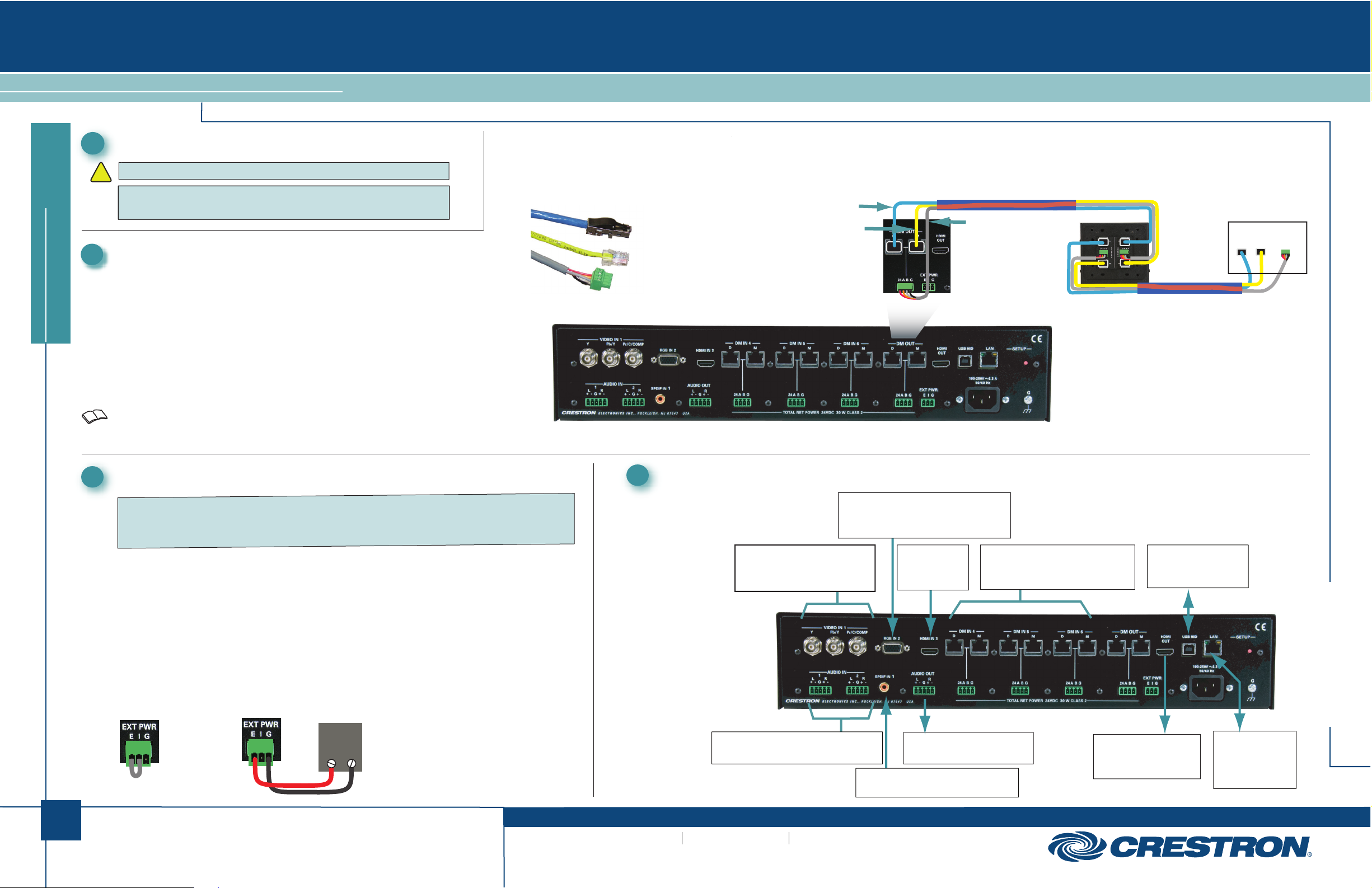
A. Using a DigitalMedia™ cable (DM-CBL-P or DM-CBL-NP), connect the
switcher output directly to a DM-RMC-100 Room Controller, or, if required,
first connect to a DM-DR Repeater and then connect the output of the
quickstart guide
DM-DR to a DM-RMC-100. The illustration immediately to the right shows
the special connectors used for the three cables contained within the
DigitalMedia cable. The illustration at the far right shows a typical wiring
configuration for the switcher’s single DM output port. (The output can
support a maximum of up to three repeaters and one room controller.)
B. For detailed instructions on operation and setup of the DM-DR
Repeater and the DM-RMC-100 Room Controller, refer to the latest
version of their respective Operations & Installation Guides (Doc. 6745
and Doc. 6743).
Connect DigitalMedia Device Power Source
3
‘D’ Video
‘M’ Data Management (CAT5E)
‘DMNet’ Control & Power
Connect Other Inputs and Outputs
4
Management
‘D’ Video
‘M’ Data
‘DMNet’
Control &
Power
DM-CBL-P
or
DM-CBL-NP
DM-DR
Repeater
DM-CBL-P
or
DM-CBL-NP
Room Controller
DM Input
D M 24ABG
1
NOTE: If a DM switcher, or other DM device supplying power, is connected to a DM IN 4-6 port
of the DM-MD6X1, then the +24V wire between the DM device and the DM-MD6X1 must be
disconnected. The A B G wires must remain connected.
A. The switcher can supply up to 30 watts of internal power to connected room
controllers repeaters and transmitters up to their rated level.
B. Ensure that the EIG jumpers are installed and wired between E and I for internal
power to be routed to the connected devices. If power is not being supplied to an external
device, make sure the jumper is not connected.
C. If the devices to be connected (both input and output) will require more power than is
available from the switcher, connect them to an external 24 VDC supply (that can supply
the required power) by connecting the E and G terminals of the EIG connector to the +
and G terminals of the (unpowered) external supply. (Refer to the illustration.)
INTERNAL
POWER
24 VDC
+ G
EXTERNAL
POWER SUPPLY
For details, refer to the latest revision of the DM-MD6X1 DigitalMedia™
Switcher Operations Guide, Doc. 6850.
QUICKSTART DOC. 6851B (2024731) 06.10
www.crestron.com
©2010 Specifications subject to
change without notice.
From Analog and Component Video
VIDEO IN 1:
From YPbPr, Composite or
S-video Sources
AUDIO IN (1-2):
Balanced Line Level Analog Audio
:
888.273.7876 201.767.3400
All brand names, product names, and trademarks
are the property of their respective owners.
RGB IN 2:
Input Sources
HDMI IN 3:
HDMI Digital
Video/Audio
AUDIO OUT:
Balanced Line Level Audio
:
SPDIF IN 1:
From Digital Audio Output
From Outputs of DM Transmitters
DM IN / 24 A B G (4-6):
or Other DM Devices
USB HID:
To USB HID Device
HDMI OUT:
HDMI Digital
Video/Audio Output
DM-MD6X1
LAN:
10BASE-T/
100BASE-TX
Ethernet to LAN
Page 2
DM-MD6X1
DigitalMedia™ Switcher
5
Apply Power
NOTE: The switcher does not have a power switch. Power is
applied to the unit by plugging in its power cords.
A. Connect the AC power cord to the switcher. Then connect the
power cord to AC power.
B. Connect power to any external 24VDC supplies that were
connected in Section 3.
quickstart guide
7
Configure the IP Address
The switcher is supplied in DHCP mode and automatically configures the IP
addresses of connected devices.
With a PC connected via USB to the COMPUTER port, use the Crestron
Toolbox™ “System Info” window to set static IP addresses for the transmitter
and room controller or DM switcher. Refer to the Toolbox help file for details.
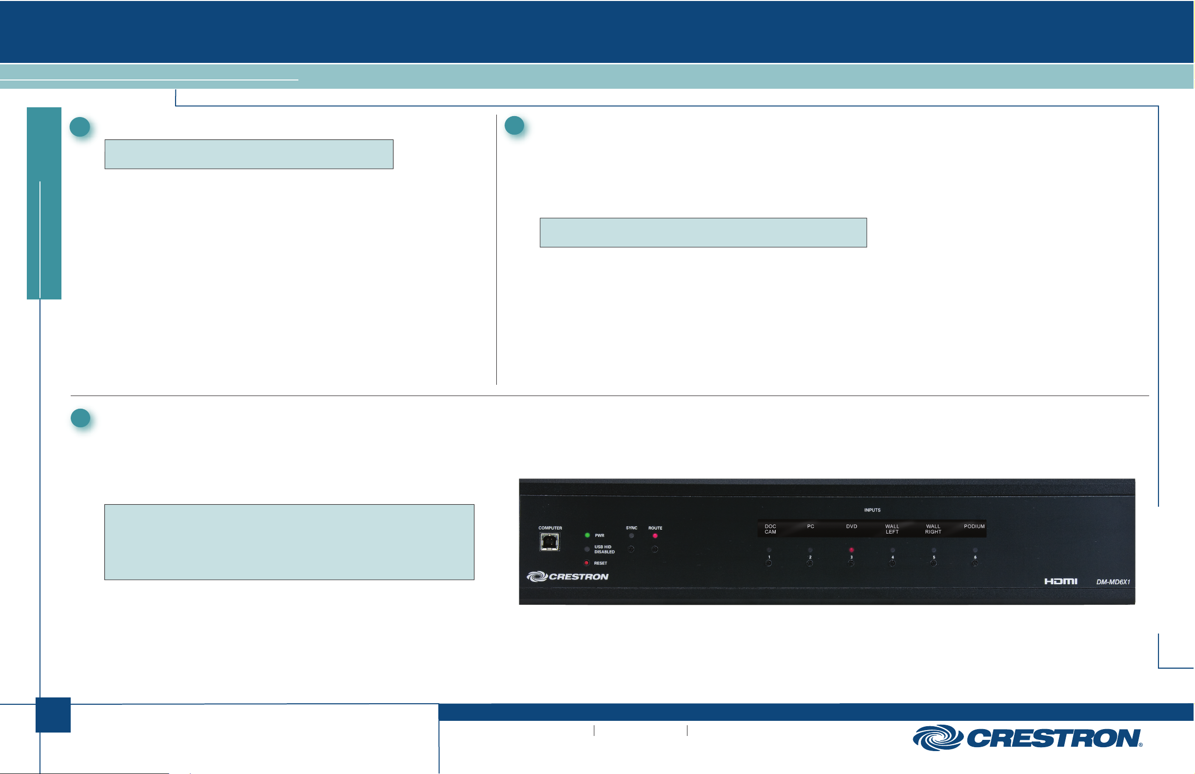
NOTE: When a PC is connected to the USB port, the USB HID DISABLED
red LED indicates that HID functionality is disabled.
When the switcher is in DHCP mode, all connected transmiters and room
controllers are set to DHCP mode.
When the switcher is in Static mode, all connected transmiters and room
controllers are set to Static mode. Settings are:
+4 for DM4
+5 for DM5
+6 for DM6
+17 for DM OUT
For example, if the switcher is set to 192.168.1.100,
devices connected to DM OUT will be set to 192.168.1.117
6
Select Input Sources
Use the front panel controls to route input sources to the output.
A. Press ROUTE, then press the desired INPUTS button to select the signal type(s)
you wish to route. The corresponding LED will light.
B. If necessary, press the RESET button to reboot the unit. All settings are retained.
NOTE: Out-of-the-box, if analog audio and digital audio inputs are both connected,
the switcher automatically selects the digital audio for routing. Programming can
allow you to choose between the two input signals.
NOTE: The SYNC LED is valid only for the last routed local source and the DM IN
source.
ROUTE
DM-MD6X1
:
2
For details, refer to the latest revision of the DM-MD6X1 DigitalMedia™
Switcher Operations Guide, Doc. 6850.
QUICKSTART DOC. 6851B (2024731) 06.10
www.crestron.com
©2010 Specifications subject to
change without notice.
888.273.7876 201.767.3400
All brand names, product names, and trademarks
are the property of their respective owners.
 Loading...