

Crestron DM-MD64X64, DM-MD128X128 Quick Start Manual
DM-MD64X64/DM-MD128X128
64X64/128X128 DigitalMedia™ Switchers
1 1
Introduction
Input/output (I/O) blades and the CPU blade are installed
prior to shipment of the Crestron® DM-MD64X64 and
DM-MD128X128:
● The DM-MD64X64 can contain up to 8 input blades
and 8 output blades. Input blades occupy input slots
1-8. Output blades occupy output slots 1-8. One
DMB-CPU-64 blade occupies the CPU slot.
● The DM-MD128X128 can contain up to 16 input
blades and 16 output blades. Input blades occupy
input slots 1-16. Output blades occupy output slots
1-16. One DMB-CPU-128 blade occupies the
CPU slot.
quickstart guide
The following illustrations show configurations of the
DM-MD64X64 and DM-MD128X128 containing one input
blade, one output blade, and the associated CPU blade.
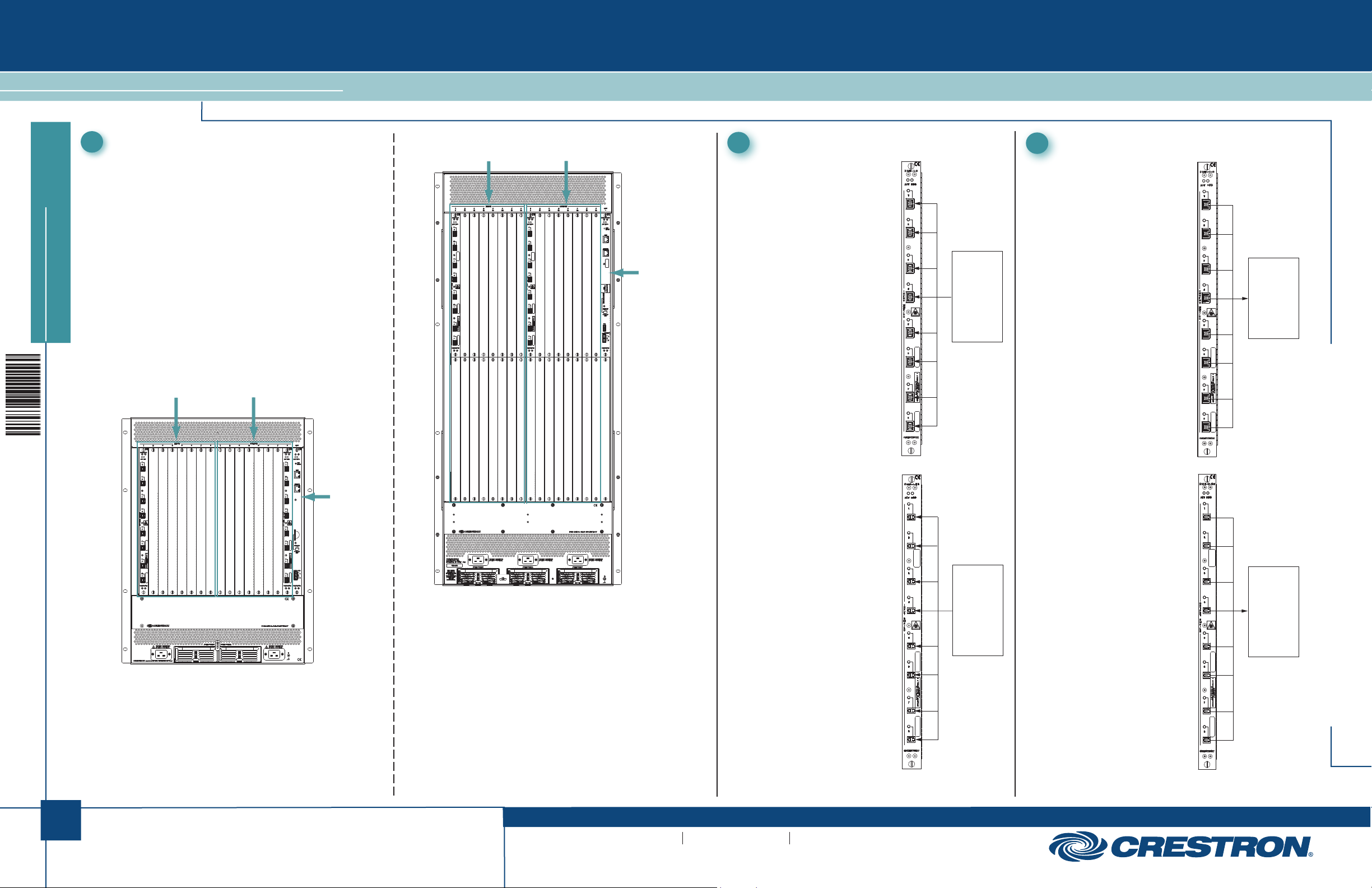
Sample DM-MD64X64 Configuration
Input Slots 1-8
Output Slots 1-8
Sample DM-MD128X128 Configuration
Input Slots 1-16
Output Slots 1-16
-B--B-
CPU Blade
2
Connecting Input Blades
DMB-I-S
Provides eight DM 8G® fiber
inputs that connect to DM 8G
fiber outputs of DM®
transmitters or other DM
devices using multimode fiber
optic cable (sold separately).
Using CRESFIBER8G, the
maximum transmission
distance is 1000 feet
(~300 meters). Using
CRESFIBER,
CRESFIBER-SINGLE-SC,
or third-party OM3 simplex
multimode fiber optic cable,
the maximum transmission
distance is 500 feet
(~150 meters).
INPUT
MMF/SC:
From DM 8G
Fiber Output
of DM
Transmitter
or
Other DM
Device
3
Connecting Output Blades
DMB-O-S
Provides eight DM 8G fiber
outputs that connect to DM
8G fiber inputs of DM
receivers or other DM devices
using multimode fiber optic
cable (sold separately). Using
CRESFIBER8G, the
maximum transmission
distance is 1000 feet
(~300 meters). Using
CRESFIBER,
CRESFIBER-SINGLE-SC,
or third-party OM3 simplex
multimode fiber optic cable,
the maximum transmission
distance is 500 feet
(~150 meters).
OUTPUT
MMF/SC:
To DM 8G
Fiber Input
of DM
Receiver or
Other DM
Device
DM-MD64X64/DM-MD128X128
CPU Blade
In the configuration above, the DM-MD64X64 contains an
input blade in input slot 1, an output blade in output slot 8,
and the DMB-CPU-64 blade in the CPU slot.
In the configuration above, the DM-MD128X128 contains an
input blade in input slot 1, an output blade in output slot 1,
and the DMB-CPU-128 blade in the CPU slot.
DMB-I-S2
Provides eight DM 8G SMF
inputs that connect to DM 8G
SMF outputs of DM
transmitters or other DM
devices using single-mode
fiber optic cable (sold
separately). Using
CRESFIBER8G-SM or
third-party G.652.D (or better)
single-mode fiber optic cable,
the maximum transmission
distance is 7.5 miles (12 km).
INPUT
SMF/LC:
From DM 8G
SMF Fiber
Output
of DM
Transmitter
or Other
DM Device
DMB-O-S2
Provides eight DM 8G
single-mode fiber outputs that
connect to DM 8G SMF
inputs of DM receivers or
other DM devices using
single-mode fiber optic cable
(sold separately). Using
CRESFIBER8G-SM or
third-party G.652.D (or better)
single-mode fiber optic cable,
the maximum transmission
distance is 7.5 miles (12 km).
OUTPUT
SMF/LC:
To DM 8G
SMF Fiber
Input
of DM
Receiver or
Other DM
Device
1
For details, refer to the latest version of the DM-MD64X64/
DM-MD128X128 DigitalMedia Switchers Operations & Installation
Guide, Doc. 7318.
QUICKSTART DOC. 7319B (2035907) 09.13
www.crestron.com
Specifications subject to
change without notice.
888.273.7876 201.767.3400
DM-MD64X64/DM-MD128X128
64X64/128X128 DigitalMedia™ Switchers
1
4
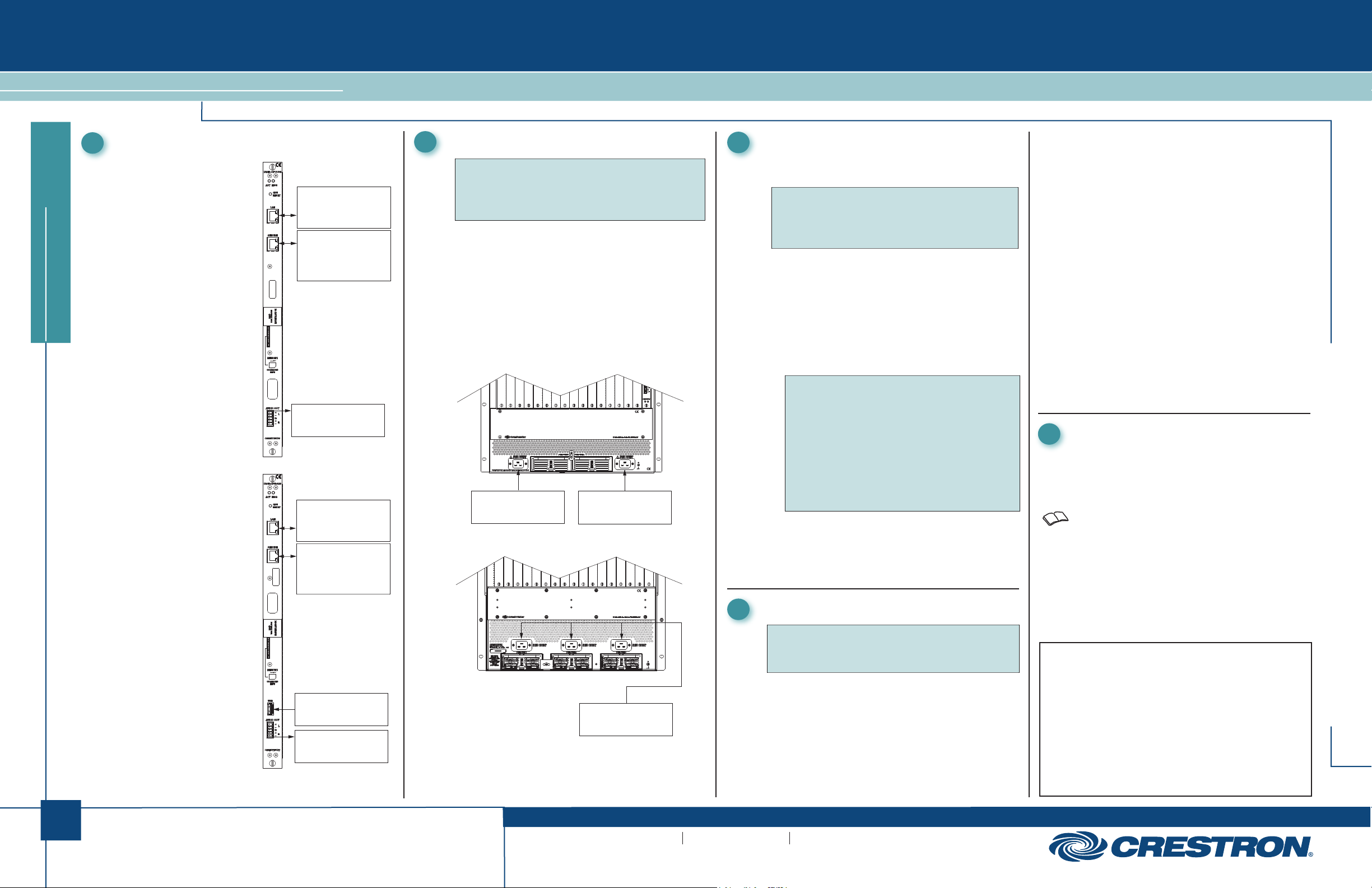
Connecting the CPU Blade
DMB-CPU-64
Provides 10BASE-T/
100BASE-TX/1000BASE-T
LAN port, computer console
SERVICE port, and AUDIO
OUT port.
quickstart guide
DMB-CPU-128
Provides 10BASE-T/
100BASE-TX/1000BASE-T
LAN port, computer console
SERVICE port, USB, and
AUDIO OUT port.
10BASE-T/100BASE-TX/
LAN:
1000BASE-T
Ethernet to LAN
SERVICE:
10BASE-T/100BASE-TX/
1000BASE-T
Computer Console Port
AUDIO OUT:
To Analog Audio Input
LAN:
10BASE-T/100BASE-TX/
1000BASE-T
Ethernet to LAN
SERVICE:
10BASE-T/100BASE-TX/
1000BASE-T
Computer Console Port
1
5
Applying Power
NOTE: The DM-MD64X64 requires two 20 A @
100-127 Vac or two 10 A @ 200-240 Vac circuits.
The DM-MD128X128 requires three 20 A @
100-127 Vac or three 10 A @ 200-240 Vac circuits.
The DM-MD64X64 contains two power supplies;
the DM-MD128X128 contains three power supplies.
The power supplies provide load balancing and
power redundancy.
To apply power to the DM switcher, connect the
supplied ac power cords to the power inlets of the
switcher. Connect the other end of the power cords to
ac power using the same ac voltage type—either
120 Vac or 220 Vac.
DM-MD64X64 Power Connections
100-127V ~ 50/60Hz 16A,
200-240V ~ 50/60Hz 8A:
Main Power Input
DM-MD128X128 Power Connections
100-127V ~ 50/60Hz 16A,
200-240V ~ 50/60Hz 8A:
Main Power Input
1
6
Configuring Network Settings
Configure network settings on the “Ethernet Setup”
screen of the DM switcher user interface:
NOTE: The “Ethernet Setup” screen
automatically appears on the front panel touch
screen after the DM switcher boots up for the
first time.
1. Set DHCP to ON or OFF. The default setting is ON
2. (Optional) Enter a hostname.
3. (Optional) Enter a domain name.
4. (Applicable only if DHCP is set to OFF
IP address, subnet mask, and default router
address.
5. Set the system ID. The default setting is
NOTE: Private Network Mode (PNM) is always
enabled. When multiple DM switchers are
cascaded, assign a unique system ID to each
switcher. PNM uses the system ID of each
switcher to determine the internal IP address
used by each device in the DM system.
NOTE: Each DM switcher must connect directly
to the LAN. A DM switcher cannot connect to the
LAN through another DM switcher.
6. Set control system connection settings:
a. Enter the IP address or hostname of the control
system connected to the DM switcher.
b. Enter the IP ID of the DM switcher.
) Enter a static
1.
To select an EDID configuration file:
1. On the “Input Blade” screen of a particular
blade, select Configure EDID for the input
whose EDID file is to be selected.
The “EDID Setup” screen appears, listing the
12 preconfigured EDID files in the Crestron
EDID List (default setting).
2. Scroll the list and then select the desired EDID
file.
.
1
1
8
A prompt appears asking confirmation that the
selected EDID file be sent to the input.
3. Select Yes to send the EDID file to the input.
The “EDID Setup” screen indicates the currently
selected EDID file.
4. If desired, select Copy to all inputs to send the
currently selected EDID file to all inputs of the
DM switcher; otherwise, select < Previous
Input or Next Input > as appropriate and repeat
steps 2 and 3 for each input.
Configuring DigitalMedia Endpoints
Advanced configuration tasks for DigitalMedia
endpoints (DM-TX transmitters and DM-RMC
receivers) include detailed scaler configuration and
configuration of video parameters (for example,
brightness and contrast). To perform such tasks,
refer to the DM-MD64X64/DM-MD128X128:
Configuring DigitalMedia Endpoints Quickstart
Guide (Doc. 7489) at www.crestron.com/manuals.
DM-MD64X64/DM-MD128X128
2
USB:
For Connection of USB
Flash Drive
AUDIO OUT:
To Analog Audio Input
For details, refer to the latest version of the DM-MD64X64/
DM-MD128X128 DigitalMedia Switchers Operations & Installation
Guide, Doc. 7318.
QUICKSTART DOC. 7319B (2035907) 09.13
100-127V ~ 50/60Hz 16A,
200-240V ~ 50/60Hz 8A:
Main Power Inputs
www.crestron.com
Specifications subject to
change without notice.
1
7
Configuring EDID
NOTE: For detailed information about EDID
configuration, refer to Answer ID 5357 at
www.crestron.com/onlinehelp.
For each input, select from among 12 preconfigured
EDID (Extended Display Identification Data)
configuration files listed on the “EDID Setup” screen of
the DM switcher user interface. If desired, an EDID file
selected for a single input can be copied
automatically to all inputs of the DM switcher.
888.273.7876 201.767.3400
The specific patents that cover Crestron products are listed at
patents.crestron.com.
Crestron, the Crestron logo, DigitalMedia, DM, and DM 8G are either
trademarks or registered trademarks of Crestron Electronics, Inc. in the
United States and/or other countries. Other trademarks, registered
trademarks, and trade names may be used in this document to refer to
either the entities claiming the marks and names or their products.
Crestron disclaims any proprietary interest in the marks and names of
others. Crestron is not responsible for errors in typography or
photography.
This document was written by the Technical Publications department at
Crestron.
©2013 Crestron Electronics, Inc.
 Loading...