

Crestron DMC-CPU3 Installation Manual
DMC-CPU3
DigitalMedia™ CPU3 Card for DM® Switchers
Installation Guide
Description
The DMC-CPU3 card is available as an upgrade to the DMC-CPU card, which is included
with the DM-MD8X8, DM-MD16X16, DM-MD32X32, and related redundant power supply
models (DM-MD8X8-RPS, DM-MD16X16-RPS, and DM-MD32X32-RPS).
This guide provides information about the following:
• Replacing the DMC-CPU with a DMC-CPU3
• Making connections to the DMC-CPU3
• Upgrading the rmware
• Conguring the DigitalMedia™ switcher
Additional Resources
Visit the product page on the Crestron® website (www.crestron.com) for additional
information.
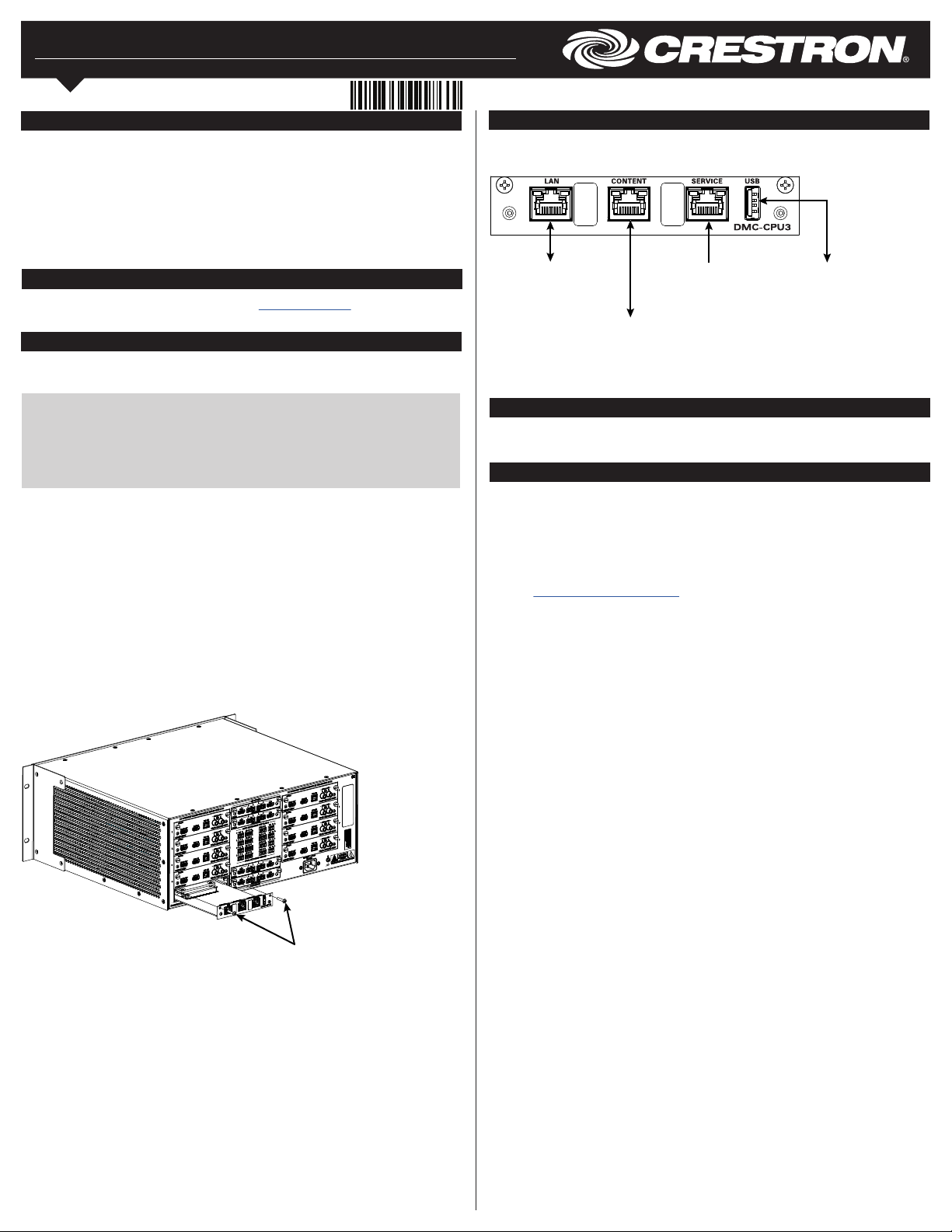
Replacing the DMC-CPU with a DMC-CPU3
To replace the DMC-CPU with a DMC-CPU3, perform the following steps and refer to the
illustration below.
CAUTION: The DMC-CPU3 is susceptible to damage from electrostatic discharge
(ESD). Standard ESD precautions must be followed when handling the card.
Always wear an ESD wrist strap that is connected to ground and place the card on
grounded surfaces only.
NOTE: The DMC-CPU3 is not hot swappable. Always shut down the DigitalMedia
switcher before installing the card.
1. Remove the DMC-CPU card:
a. Disconnect the LAN cable from the card.
b. Using a #2 Phillips screwdriver (not included), loosen the two 6-32 x 3/4-inch
Phillips pan head screws that secure the card to the card assembly, and then
slide the card out of the slot.
2. Install the DMC-CPU3 card:
a. Carefully insert the card into the left and right guides of the CPU slot until the card
is 1/4 inch from the fully seated position.
b. Align the two included 6-32 x 3/4-inch Phillips pan head screws with the
corresponding holes in the card assembly, and then push the card inward until it
engages the chassis backplane.
c. Tighten the two Phillips screws to secure the card—do not overtighten
the screws.
DMC-CPU3 Card Installation (DM-MD8X8 Shown)
Making Connections to the DMC-CPU3
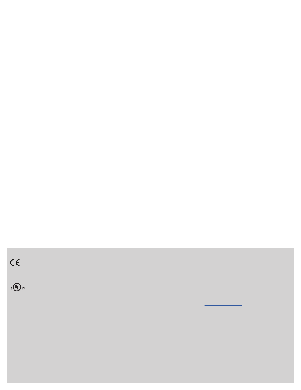
Make connections to the DMC-CPU3 as required for the application.
DMC-CPU3 Connections
LAN:
10BASE-T/100BASE-TX/
1000BASE-T Ethernet
to LAN
CONTENT:
10BASE-T/100BASE-TX/
1000BASE-T Ethernet
to LAN
(for streaming only)
SERVICE:
For factory
use only
USB:
For rmware
loading
Upgrading the Firmware
Upgrade the firmware of all DMC cards in the switcher and the firmware of all
®
DM
endpoints. The latest firmware file can be downloaded from the Crestron website.
Conguring the DigitalMedia Switcher
Congure the DigitalMedia™ switcher by using the web interface and DMTool.
To access the web interface, open a web browser and enter either of the following:
hostname/setup (hostname is the hostname of the switcher)
or
xxx.xxx.xxx.xxx/setup (xxx.xxx.xxx.xxx is the IP address of the switcher)
For more information, refer to OLH ID 1000200 in the Online Help section of the Crestron
website (www.crestron.com/onlinehelp).
6-32 x 3/4-inch
Phillips pan head screws
As of the date of manufacture, the product has been tested and found to comply with specications for
CE marking.
This product is Listed to applicable UL® Standards and requirements tested by Underwriters
Laboratories Inc.
Ce produit est homologué selon les normes et les exigences UL applicables par Underwriters
Laboratories Inc.
Federal Communications Commission (FCC) Compliance Statement
This device complies with part 15 of the FCC Rules. Operation is subject to the following conditions:
(1) This device may not cause harmful interference and (2) this device must accept any interference
received, including interference that may cause undesired operation.
CAUTION: Changes or modications not expressly approved by the manufacturer responsible for
compliance could void the user’s authority to operate the equipment.
NOTE: This equipment has been tested and found to comply with the limits for a Class B digital device,
pursuant to part 15 of the FCC Rules. These limits are designed to provide reasonable protection
against harmful interference in a residential installation. This equipment generates, uses and can radiate
radio frequency energy and, if not installed and used in accordance with the instructions, may cause
harmful interference to radio communications. However, there is no guarantee that interference will not
occur in a particular installation.
If this equipment does cause harmful interference to radio or television reception, which can be
determined by turning the equipment off and on, the user is encouraged to try to correct the
interference by one or more of the following measures:
• Reorient or relocate the receiving antenna.
• Increase the separation between the equipment and receiver.
• Connect the equipment into an outlet on a circuit different from that to which the receiver is
connected.
• Consult the dealer or an experienced radio/TV technician for help.
Industry Canada (IC) Compliance Statement
CAN ICES-3(B)/NMB-3(B)
The product warranty can be found at www.crestron.com/warranty.
The specic patents that cover Crestron products are listed at www.crestron.com/legal/patents.
Certain Crestron products contain open source software. For specic information, please visit
www.crestron.com/opensource.
Crestron, the Crestron logo, DigitalMedia, and DM are either trademarks or registered trademarks of
Crestron Electronics, Inc. in the United States and/or other countries. UL and the UL logo are either
trademarks or registered trademarks of Underwriters Laboratories, Inc. in the United States and/or
other countries. Other trademarks, registered trademarks, and trade names may be used in this
document to refer to either the entities claiming the marks and names or their products.
Crestron disclaims any proprietary interest in the marks and names of others. Crestron is not
responsible for errors in typography or photography.
This document was written by the Technical Publications department at Crestron.
©2018 Crestron Electronics, Inc.
Crestron Electronics, Inc. Installation Guide - DOC. 8364A
15 Volvo Drive, Rockleigh, NJ 07647 (2052506)
Tel: 888.CRESTRON 08.18
Fax: 201.767.7576 Specications subject to
www.crestron.com change without notice.
 Loading...