

Crestron DMB-4K-CPU-128, DMB-CPU-128, DMB-CPU-64, DMB-4K-CPU-64 Installation Manuals
DMB Series
DigitalMedia™ Blades
Installation Guide
Description
DMB blades occupy the DM-MD64X64 and DM-MD128X128 DigitalMedia™ switchers.
This document provides installation instructions for the following:
• Adding or replacing a DMB input/output (I/O) blade
• Replacing the DMB CPU blade
Additional Resources
Visit the product page on the Crestron® website (www.crestron.com)
for additional information and the latest rmware updates. Use a QR
reader application on your mobile device to scan the QR image.
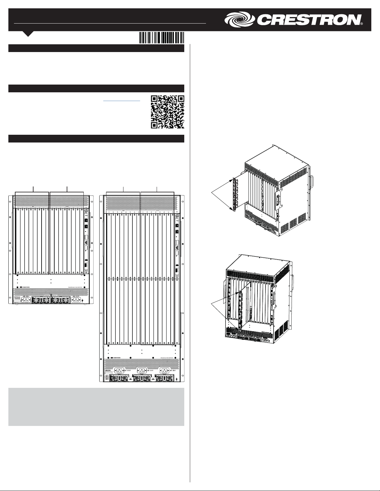
Adding or Replacing a DMB I/O Blade
DMB input blades occupy input slots 1 through 8 of the DM-MD64X64 and input slots
1 through 16 of the DM-MD128X128. DMB output blades occupy output slots 1 through 8
of the DM-MD64X64 and output slots 1 through 16 of the DM-MD128X128. Refer to the
following illustrations for slot locations.
DM-MD64X64 DMB I/O Blade Slots DM-MD128X128 DMB I/O Blade Slots
Input slots
1-8
Output slots
1-8
Input slots
1-16
Output slots
1-16
To add or replace a DMB I/O blade, perform the following steps and refer to the
illustrations below.
1. Do either of the following:
• If adding an I/O blade, remove the slot cover of an unused input or output slot as
appropriate by loosening the two thumb screws.
• If replacing an I/O blade, disconnect all cables from the blade being replaced,
loosen the two thumb screws that secure the blade to the blade assembly, and
then slide the blade out of the slot.
2. Carefully insert the new blade into the guides at the top and bottom of the selected
slot until the blade is 1/4 inch from the fully seated position.
3. Align the two thumb screws of the blade with the corresponding holes in the blade
assembly, and then push the blade inward until it is fully seated and engages the
chassis backplane.
4. Finger-tighten the two thumb screws to secure the blade—do not overtighten the
screws.
5. Reconnect the cables to the blade.
Input Blade Installation (DM-MD64X64 Shown)
Thumb
screws
CAUTION: DMB I/O blades are susceptible to damage from electrostatic discharge
(ESD). Standard ESD precautions must be followed when handling the blades. Always
wear an ESD wrist strap that is connected to ground, and place blades on grounded
surfaces only.
NOTE: DMB I/O blades are hot swappable; therefore, the blades can be installed
without the need to shut down the DigitalMedia switcher.
Output Blade Installation (DM-MD64X64 Shown)
Thumb
screws
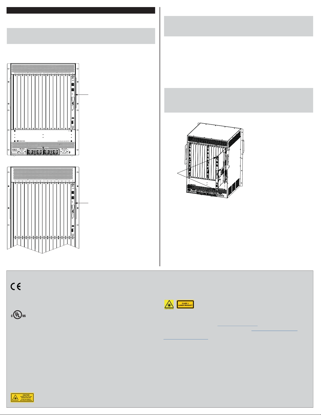
Replacing the DMB CPU Blade
The DMB-4K-CPU-64 blade occupies the CPU slot of the DM-MD64X64; the
DMB-4K-CPU-128 blade occupies the CPU slot of the DM-MD128X128.
NOTE: The information in this section also applies to the DMB-CPU-64 and
DMB-CPU-128 blades, which are earlier models of the DMB-4K-CPU-64 and
DMB-4K-CPU-128 blades, respectively.
Refer to the following illustrations for the location of the DMB CPU blade in a
DM-MD64X64 and DM-MD128X128.
DMB CPU Blade in DM-MD64X64 CPU Slot (DMB-4K-CPU-64 Shown)
DMB-4K-CPU-64
blade
To replace the DMB CPU blade, perform the following steps and refer to the illustration
below.
CAUTION: The DMB CPU blade is susceptible to damage from electrostatic discharge
(ESD). Standard ESD precautions must be followed when handling the blade. Always
wear an ESD wrist strap that is connected to ground, and place the blade on a
grounded surface only.
1. Disconnect all cables from the blade, loosen the two thumb screws that secure the
blade to the blade assembly, and then slide the blade out of the slot.
2. Carefully insert the new blade into the guides at the top and bottom of the CPU slot
until the blade is 1/4 inch from the fully seated position.
3. Align the two thumb screws of the blade with the corresponding holes in the blade
assembly, and then push the blade inward until it is fully seated and engages the
chassis backplane.
4. Finger-tighten the two thumb screws to secure the blade—do not overtighten the
screws.
5. Reconnect the cables to the blade.
NOTE: If the DMB-CPU-64 blade is being replaced with a DMB-4K-CPU-64 blade or if
the DMB-CPU-128 blade is being replaced with a DMB-4K-CPU-128 blade, be sure to
upgrade the rmware of all DMB I/O blades in the switcher. The latest rmware le can
be downloaded from the Crestron website after logging in to the website as an
authorized user.
DMB CPU Blade Installation into CPU Slot (DM-MD64X64 Shown)
DMB CPU Blade in DM-MD128X128 CPU Slot (DMB-4K-CPU-128 Shown)
DMB-4K-CPU-128
blade
As of the date of manufacture, the DMB Series blades have been tested and found to comply with
specications for CE marking.
This product is Listed to applicable UL® Standards and requirements tested by Underwriters
Laboratories Inc.
Ce produit est homologué selon les normes et les exigences UL applicables par Underwriters
Laboratories Inc.
Federal Communications Commission (FCC) Compliance Statement
This device complies with part 15 of the FCC Rules. Operation is subject to the following conditions:
(1) This device may not cause harmful interference and (2) this device must accept any interference
received, including interference that may cause undesired operation.
CAUTION: Changes or modications not expressly approved by the manufacturer responsible for
compliance could void the user’s authority to operate the equipment.
NOTE: This equipment has been tested and found to comply with the limits for a Class A digital device,
pursuant to part 15 of the FCC Rules. These limits are designed to provide reasonable protection
against harmful interference when the equipment is operated in a commercial environment. This
equipment generates, uses, and can radiate radio frequency energy and, if not installed and used in
accordance with the instruction manual, may cause harmful interference to radio communications.
Operation of this equipment in a residential area is likely to cause harmful interference in which case the
user will be required to correct the interference at his own expense.
Industry Canada (IC) Compliance Statement
CAN ICES-3(A)/NMB-3(A)
The product is a class 1M laser product. It complies with safety regulations of IEC-60825-1, FDA 21
CFR 1040.11 and FDA 21 CFR 1040.10.
Thumb
screws
WARNING: Invisible laser radiation may be emitted from disconnected bers or connectors. Do not
stare into beams or view directly with optical instruments.
NOTE: Plug the included dust caps into the optical transceivers when the ber optic cable is
unplugged.
The product is a class 1 laser product. It complies with safety regulations of IEC-60825-1, FDA 21
CFR 1040.11 and FDA 21 CFR 1040.10.
WARNING: Visible and invisible laser radiation when open. Avoid direct exposure to beam.
NOTE: Plug the included dust cap into the optical transceiver when the fiber optic cable is unplugged.
The product warranty can be found at www.crestron.com/warranty
The specic patents that cover Crestron products are listed at www.crestron.com/legal/patents.
Certain Crestron products contain open source software. For specic information, please visit
www.crestron.com/opensource.
Crestron, the Crestron logo, and DigitalMedia are either trademarks or registered trademarks of
Crestron Electronics, Inc. in the United States and/or other countries. UL and the UL logo are either
trademarks or registered trademarks of Underwriters Laboratories, Inc. in the United States and/or
other countries.Other trademarks, registered trademarks, and trade names may be used in this
document to refer to either the entities claiming the marks and names or their products. Crestron
disclaims any proprietary interest in the marks and names of others. Crestron is not responsible for
errors in typography or photography.
This document was written by the Technical Publications department at Crestron.
©2017 Crestron Electronics, Inc.
Crestron Electronics, Inc.
15 Volvo Drive, Rockleigh, NJ 07647
Tel: 888.CRESTRON
Fax: 201.767.7576
www.crestron.com change without notice.
.
Installation Guide - DOC. 7486E
Specications subject to
(2035927)
11.17
 Loading...