

Crestron DM-8G-CONN-100, DM-8G-CRIMP Quick Start Manual
DM-8G-CONN-100 and DM-8G-CRIMP
DigitalMedia 8G™ Connectors and Crimper
Introduction
1
DM-8G-CONN-100 and DM-8G-CRIMP are used to
terminate Crestron® DigitalMedia 8G™ cable
(DM-CBL-8G):
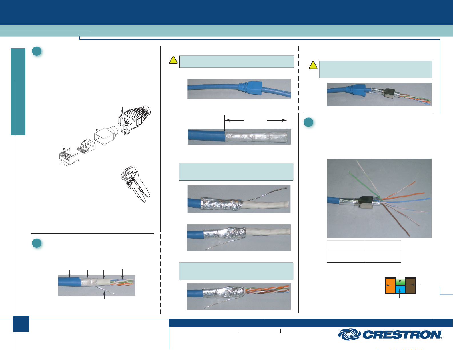
● DM-8G-CONN-100 contains 100 RJ-45 shielded
modular plug connectors. As shown in the illustration
below, a DM-8G-CONN connector is comprised of a
housing, a load bar, and a plug shield. A boot
provides a protective covering and strain relief for
the connector.
quickstart guide
Housing
● DM-8G-CRIMP (sold separately
from DM-8G-CONN-100) is a
tool that allows hand crimping of
the DM-8G-CONN connector
for proper cable termination.
Additional items (not supplied) required for termination
of the DM-CBL-8G cable are the following:
● Wire or diagonal cutter
● Razor knife or scissors
Preparing the Cable
2
A sectional view of DM-CBL-8G shielded twisted pair
(STP) cable is shown below.
Cable
Jacket
Plug Shield
Load Bar
Foil
Shield
Inner
Jacket
Drain
Wire
Boot
(4) Wire
Pairs
To prepare the cable for termination, do the following:
CAUTION: Do not nick the insulation of the wires or the
!
foil shield of the cable.
1. Slide the boot over the end of the cable.
2. Strip the cable jacket 1½ inches (38 mm) from the end
of the cable.
1½ in
(38 mm)
3. Fold back the foil shield so that it lies smoothly over the
cable jacket.
NOTE: If the cable you are using has a wire braid, fold
back the braid over the cable jacket and then fold back
the foil sheid over the braid.
4. Fold back the drain wire over the foil shield.
5. Cut and remove the white inner jacket.
NOTE: If the cable you are using has a clear plastic
wrap instead of a white inner jacket, cut and remove
the plastic wrap.
6. Slide the plug shield over the drain wire and foil shield
past the stripped end of the cable jacket.
CAUTION: The foil shield should be visible on both sides
!
of the plug shield. Do not slide the plug shield past the
back end of the foil shield.
Positioning the Cable
1
3
To position the cable for insertion into the connector,
do the following:
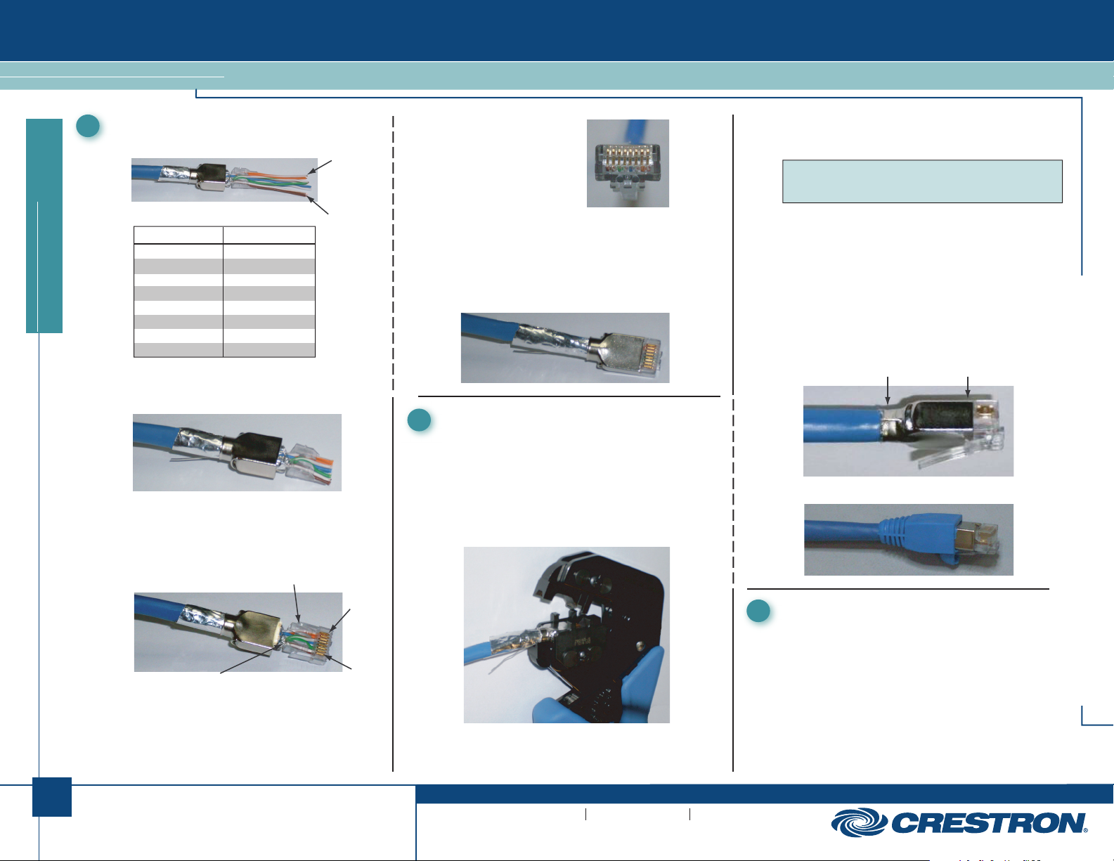
1. Untwist each of the four twisted wire pairs.
2. Straighten and arrange the orange, blue, and brown
wire pairs, and then fold back the green wire pair.
G/W
G
O/W = Orange/White
O = Orange
Br/W = Brown/White
Br = Brown
3. Insert the orange,
blue, and brown
wire pairs through
the load bar, and
then insert the
green wire pair
into the slot of
the load bar.
Bl = Blue
Bl/W = Blue/White
G/W = Green/White
G = Green
Green Pair
Orange
Pair
Blue Pair
DM-8G-CONN-100 and DM-8G-CRIMP
O/W
O
Bl
Bl/W
Br/W
Br
Brown
Pair
1
QUICKSTART DOC. 7064B (2028626) 02.11
www.crestron.com
©2011 Specifications subject to
change without notice.
888.273.7876 201.767.3400
All brand names, product names, and trademarks
are the property of their respective owners.
DM-8G-CONN-100 and DM-8G-CRIMP
DigitalMedia 8G™ Connectors and Crimper
Positioning the Cable (Continued)
1
1
3
4. Arrange the wire pairs for T568B termination.
T568B Pin Assignments
PIN NUMBER
1
2
3
quickstart guide
5. While holding down all wires against the load bar in
6. While holding all wires down against the load bar,
4
5
6
7
8
a flat layer, trim all wires evenly up to the front edge
of the load bar.
insert the front of the load bar and the ends of the
wires into the cavity of the housing. Push the load
bar into the housing until the load bar latches into
the notch on both sides of the housing.
COLOR
Orange/White
Orange
Green/White
Blue
Blue/White
Green
Brown/White
Brown
Notch
To Pin 1
(Orange/
White)
To Pin 8
(Brown)
Pin 1
7. Visually verify that all
wires are fully inserted
into the housing with the
end of the wires seated
against the end of the
housing cavity. If not,
push the cable further
into the load bar until it
latches into both sides
of the housing.
8. Slide the plug shield over the modular plug
subassembly until the plug shield is seated against the
front edge of the recessed area around the outside of
the housing.
Terminating the Connector
4
T
o terminate the connector, proceed as folows:
1. Using the DM-8G-CRIMP tool, do the following:
a. Close the tool handles until the ratchet releases,
and then allow the handles to open fully.
b. With the tab of the housing facing downward, insert
the modular plug (including shield and cable) into
the crimping chamber.
c. While holding the assembly, carefully close the tool
handles until the ratchet releases, and then allow
the handles to open fully.
NOTE: The tool terminates three areas of the modular
plug. For proper alignment, be sure to apply forward
pressure on the cable while closing the tool handles.
d. Remove the modular plug from the tool.
e. Trim away excess drain wire, foil shield, and wire
braid that extend beyond the end of the
plug shield.
f. Verify the following:
● The plug shield is free of bulges and tears.
● The strain relief end of the plug shield is held
the plug shield is against the raised edge of
the housing.
2. Slide the boot over the crimped connector.
firmly in place on the cable. The shield end of
Strain Relief Shield
1
Testing the Cable
5
Using a shielded twisted pair (STP) cable tester such as
the IDEAL® LinkMaster™ tester, test the cable to ensure
that it is terminated properly.
DM-8G-CONN-100 and DM-8G-CRIMP
2
Notch
QUICKSTART DOC. 7064B (2028626) 02.11
Pin 8
www.crestron.com
©2011 Specifications subject to
change without notice.
888.273.7876 201.767.3400
All brand names, product names, and trademarks
are the property of their respective owners.
 Loading...