

Page 1

DIN-TSTAT-FCU
DIN-Rail Heating and Cooling Fan-Coil
Thermostat
Setup and Commissioning Guide
Crestron Electronics, Inc.
Page 2

Crestron product development software is licensed to Crestron dealers and Crestron Service Providers (CSPs) under a limited non-exclusive,
non-transferable Software Development Tools License Agreement. Crestron product operating system software is licensed to Crestron
dealers, CSPs, and end-users under a separate End-User License Agreement. Both of these Agreements can be found on the Crestron
website at www.crestron.com/legal/software_license_agreement.
The product warranty can be found at www.crestron.com/warranty.
The specific patents that cover Crestron products are listed at www.crestron.com/legal/patents.
Certain Crestron products contain open source software. For specific information, please visit www.crestron.com/opensource.
Crestron, the Crestron logo, and Cresnet are either trademarks or registered trademarks of Crestron Electronics, Inc. in the United States
and/or other countries. Modbus is either a trademark or registered trademark of SCHNEIDER ELECTRIC USA, INC., in the United States
and/or other countries. Windows is either a trademark or registered trademark of Microsoft Corporation in the United States and/or other
countries. Other trademarks, registered trademarks, and trade names may be used in this document to refer to either the entities claiming the
marks and names or their products. Crestron disclaims any proprietary interest in the marks and names of others. Crestron is not responsible
for errors in typography or photography.
This document was written by the Technical Publications department at Crestron.
©2017 Crestron Electronics, Inc.
Page 3

Contents
Introduction 1
Supported FCUs............................................................................................................ 1
Specifications ................................................................................................................ 1
Port Descriptions ........................................................................................................... 2
Safety Notes .................................................................................................................. 3
Device Parameters 4
Regulation Algorithms 6
FCU Wiring and Control 7
Initialization .................................................................................................................... 7
Water temperature ......................................................................................................... 7
Initial Operating Parameters ........................................................................................... 8
Modulated 0-10 Vac Valve ............................................................................................. 8
Modulated OP-CL 24 Vac Valve .................................................................................. 10
Spring-loaded 24 Vac Valve......................................................................................... 12
Modulated OP-CL 230 Vac Valve ................................................................................ 14
Spring-loaded 230 Vac Valve....................................................................................... 16
1-2 Stage Direct-expansion System ............................................................................ 18
Fan Speed Control ...................................................................................................... 20
Alarms 21
Temperature Probes 21
Cresnet® Communications 22
Port ............................................................................................................................. 22
Communication ........................................................................................................... 22
Joins ............................................................................................................................ 23
Light and Poll ............................................................................................................... 24
AUX Port 25
Port ............................................................................................................................. 25
Communication ........................................................................................................... 26
Registers ..................................................................................................................... 27
Parameters .................................................................................................................. 27
USB Port 27
Setup and Commissioning Guide – DOC. 8207A Contents • i
Page 4

Accessing USB Port .................................................................................................... 27
USB Driver Installation Procedure ................................................................................ 29
Install the DIN-TSTAT-FCU Configuration Tool 31
Using the DIN-TSTAT-FCU Configuration Tool 34
Menu Overview ............................................................................................................ 34
File Menu .............................................................................................................. 34
ComPort Menu ..................................................................................................... 35
Device Menu ......................................................................................................... 35
Configure the DIN-TSTAT-FCU .................................................................................... 40
Toolbar Bar ........................................................................................................... 40
Status Bar ............................................................................................................. 40
Main Screen .......................................................................................................... 40
Monitoring ............................................................................................................. 41
Variable Forcing .................................................................................................... 42
Troubleshooting 42
Error Code ................................................................................................................... 42
Troubleshooting ........................................................................................................... 43
ii • Contents Setup and Commissioning Guide – DOC. 8207A
Page 5

Electrical specifications
Binary outputs
Valve outputs
Binary inputs
Analog inputs
DIN-TSTAT-FCU: DIN-Rail Fan-Coil
Thermostat
Introduction
The Crestron® fan-coil controller DIN-TSTAT-FCU is a universal 2-pipe, 3-speed fan-coil unit
(FCU) controller designed for use in two-pipe applications. A wide range of I/O resources
and various FCU types are supported.
Supported FCUs
The DIN-TSTAT-FCU supports the following FCU types:
Type 1 - Modulated 0-10 Vac Valve
Type 2 - Modulated OP-CL 24 Vac Valve
Type 3 - Spring-loaded 24 Vac Valve
Type 4 - Modulated OP-CL 230 Vac Valve
Type 5 - Spring-loaded 230 Vac Valve
Type 6 - 1-2 Stage Direct-expansion System
Specifications
The specifications for the DIN-TSTAT-FCU are listed below.
DIN-TSTAT-FCU Specifications
SPECIFICATION DETAILS
Power supply
Main: 230 Vac ±10%, 50 Hz, 15 W max
Cresnet: 24 Vdc ±10%, 0.5 W max
3 relays 16 A for fan control*
2 relays 16 A for valve or compressor
control**
0–10 Vdc
Modulated OP-CL triac; 24 Vac, 6 W valves
4 potential free inputs
2x NTC temperature probe: 10 K, 12 K,
15 K, and 20 K supported
Setup and Commissioning Guide – DOC. 8207A DIN-TSTAT-FCU: DIN-Rail Fan-Coil Thermostat • 1
(continued on the following page)
Page 6

Communication channels
Primary port
Auxiliary port
USB mini
Operating temperature
Storage temperature
Operating humidity
Protection degree
Mounting
Dimensions
Weight
DIN-TSTAT-FCU Specifications (continued)
SPECIFICATION DETAILS
Cresnet
RS-485, Modbus® protocol master
Service port for programming
-10–55 °C
-40–85 °C
95% max RH noncondensing
IP20
DIN rail, for indoor use only
161.6 x 90 x 62.2 mm
600 g
* Only one fan speed relay can be active at the time.
** If one stage relay is active at one time, the maximum current is 16 A; if two stage relays are active at one time,
the sum of both currents must not exceed 20 A and the current through one relay must not be greater than 16 A.
Port Descriptions
The illustration below depicts the port arrangements of the DIN-TSTAT-FCU. The following
table lists a description of the ports.
2 • DIN-TSTAT-FCU: DIN-Rail Fan-Coil Thermostat Setup and Commissioning Guide – DOC. 8207A
Page 7

E
External protective earth
4 DI0
Digital input 1
NC
No connection
CDI
Digital inputs common terminal
N
Main power supply - Neutral
DI1
Digital input 2
N
Main power supply - Neutral
CDI
Digital inputs common terminal
N
Main power supply - Neutral
DI2
Digital input 3
L
Main power supply - Live
CDI
Digital inputs common terminal
L
Main power supply - Live
DI3
Digital input 4
L
Main power supply - Live
CDI
Digital inputs common terminal
L1
Common for fan supply
5 EP
AUX port power supply output
FL
Fan speed low
A AUX port + communication line
FM
Fan speed medium
B AUX port – communication line
FH
Fan speed high
G AUX port ground
NC
No connection
24
Cresnet power supply input
L2
Common for stage supply
Y Cresnet + communication line
ST1
Stage 1 relay output
Z Cresnet – communication line
ST2
Stage 2 relay output
G Cresnet ground
OP
Valve open triac output
6 TS1
NTC probe 1 input
24V
24Vac power supply output
G Ground
CL
Valve close triac output
TS2
NTC probe 2 input
0-10
Analog 0-10V output
N/A
N/A
G
Ground
N/A
N/A
DIN-TSTAT-FCU Port Descriptions
PORT NAME DESCRIPTION PORT NAME DESCRIPTION
1
2
3
24V 24Vac power supply output G Ground
Safety Notes
• Do not use the device outside the specified field of application, especially in aircraft
or in any other airborne means of transport.
• Properly trained personnel must install the device.
• Observe any and all legal regulations or regulations issued by authorities.
• The device may only be opened at the manufacturer’s site. It does not contain any
parts that can be replaced or repaired by the user.
• The device contains electrical and electronic components and is not allowed to be
disposed of as household refuse. All locally valid regulations and requirements must
be observed.
Setup and Commissioning Guide – DOC. 8207A DIN-TSTAT-FCU: DIN-Rail Fan-Coil Thermostat • 3
Page 8

FCU type
1
1-6 Type 1: Modulated 0-10 Vac Valve
System
Regulation step
4
1-10
Regulation step (the width of the zone
regulated) in multiples of 0.5 °C
Valve minimum position
0
0-100
Minimum valve position when set point
is reached (1000 = 100%)
Fan speed OFF enable
1
0-1 If 0, fan will stay in speed 1 when the
is turned OFF
Fan speed change delay
1
1-10
[min]
Minimum time between two fan speed
changes
PI regulaton: Kp
20
1-500
PI regulator proportional parameter
PI regulaton: Ti
300100
0-600
PI regulator integration parameter
Temperature probe 1 type
NTC 20K
NTC 20K,
NTC 15K
Type of the temperature probe on
Temperature probe 2
enable
0
0-1 Enable usage of temperature probe on
analog input 2
Device Parameters
Using the DIN-TSTAT-FCU Commissioning Tool, configure the DIN-TSTAT-FCU according
to the FCU type, valve parameters, and other requirements. Parameters are divided into
common and specific to each FCU type.
The common parameter to all FCUs that are subdivided by regulation, communication, and
alarm parameters. The first common parameter determines the FCU type.
Parameters specific to FCU type are presented in respective tables:
• Modulated 0-10 Vac Valve
• Modulated OP-CL 24 Vac valve
• Spring-loaded 24 Vac Valve
• Modulated OP-CL 230 Vac Valve
• Spring-loaded 230 Vac Valve
• 1-2 Stage Direct-expansion System
Common Parameters
SPECIFICATION DEFAULT RANGE UNITS COMMENTS
Regulation Parameters
SPECIFICATION DEFAULT RANGE UNITS COMMENTS
NTC 10K,
NTC 12K,
Type 2: Modulated OP-CL 24 Vac
valve
Type 3: Spring-loaded 24 Vac Valve
Type 4: Modulated OP-CL 230 Vac
Valve
Type 5: Spring-loaded 230 Vac Valve
Type 6: 1-2 Stage Direct-expansion
around set point where the valve is
set point is reached; otherwise the fan
analog input 1 (1 - 20K NTC, 2 - 10K
NTC, 3 - 12K NTC, 4 - 15K NTC)
(Continued on the following page)
4 • DIN-TSTAT-FCU: DIN-Rail Fan-Coil Thermostat Setup and Commissioning Guide – DOC. 8207A
Page 9

Temperature probe 2 type
NTC 20K
NTC 20K,
NTC 15K
Type of the temperature probe on
cooling to work (fluid must be colder)
Minimum T diff for heating
10
0-20
°C
Minimum difference between ambient
cooling to work (fluid must be hotter)
Minimum set point for
heating
16
16-30
°C
Minimum set point value when heating
is active
Maximum set point for
heating
30
16-30
°C
Maximum set point value when heating
is active
Minimum set point for
cooling
16
16-30
°C
Minimum set point value when cooling
is active
Maximum set point for
cooling
30
16-30
°C
Maximum set point value when cooling
is active
Modbus baud
0
0–8 Modbus baud rate 0-0, 1-1200,
38400, 7-57600, 8-115200
Modbus parity
0
0–2 Modbus parity 0-no, 1-odd,
2-even
Modbus stop
2
1–2 Modbus number of stop bits
Modbus slave address
1
1–247
Modbus slave address of remote
display unit
Set point address
45001
0–65535
Address of temperature set point
register on remote display unit
Fan speed address
45002
0–65535
Address of fan speed register on
remote display unit
Mode address
45003
0–65535
Address of mode register on remote
display unit
Air temperature address
45011
0–65535
Address of register for ambient
temperature on remote display unit
Set point min address
45012
0–65535
Address of register for minimum set
point on remote display unit
Set point max address
45013
0–65535
Address of register for maximum set
point on remote display unit
Alarm 1 enable
0
Alarm 1 enable
Alarm 1 polarity
1
Alarm 1 active level
Alarm 1 delay
5
0–2000
[s]
Alarm 1 delay
Alarm 2 enable
0
0–1
Alarm 2 enable
Alarm 2 polarity
1
0–1
Alarm 2 active level
Alarm 2 delay
5
[s]
Alarm 2 delay
Alarm 3 enable
0
Alarm 3 enable
Alarm 3 polarity
1
0–1
Alarm 3 active level
Regulation Parameters (continued)
SPECIFICATION DEFAULT RANGE UNITS COMMENTS
NTC 10K,
NTC 12K,
Minimum T diff for cooling 10 0-20 °C Minimum difference between ambient
analog input 2 (1 - 20K NTC, 2 - 10K
NTC, 3 - 12K NTC, 4 - 15K NTC)
temperature and fluid temperature for
temperature and fluid temperature for
Communication Parameters
SPECIFICATION DEFAULT RANGE UNITS COMMENTS
2-2400, 3-4800, 4-9600, 5-19200, 6-
Alarms Parameters
SPECIFICATION DEFAULT RANGE UNITS COMMENTS
(Continued on the following page)
Setup and Commissioning Guide – DOC. 8207A DIN-TSTAT-FCU: DIN-Rail Fan-Coil Thermostat • 5
0–1
0–1
0–2000
0–1
Page 10

Alarm 3 delay
5
0–2000
[s]
Alarm 3 delay
Alarm 4 enable
0
Alarm 4 enable
Alarm 4 polarity
1
0–1
Alarm 4 active level
Alarm 4 delay
5
0–2000
[s]
Alarm 4 delay
Valve opening time
120
20–300
[s]
Time required for valve to open
Valve opening time
120
60–300
[s]
Time required for valve to open
Valve closing time
120
60–300
[s]
Time required for valve to close
Reset valve error interval
8
4–24
[h]
Interval between two position error
annulations
Valve opening time
120
10–300
[s]
Time required for valve to open
Valve closing time
120
10–300
[s]
Time required for valve to close
Valve opening time
120
20–300
[s]
Time required for valve to open
Valve closing time
120
20–300
[s]
Time required for valve to close
Reset valve error interval
8
4–24
[h]
Interval between two position error
annulations
Valve opening time
120
10–300
[s]
Time required for valve to open
Valve closing time
120
10–300
[s]
Time required for valve to close
Stage 1 minimum ON time
300
60–1200
[s]
Minimum operating time for
compressor first stage
Stage 2 minimum ON time
300
60–1200
[s]
Minimum operating time for
compressor second stage
Alarms Parameters (continued)
SPECIFICATION DEFAULT RANGE UNITS COMMENTS
0–1
Parameters for Type 1 - Modulated 0-10 Vac Valve
SPECIFICATION DEFAULT RANGE UNITS COMMENTS
Parameters for Type 2 - Modulated OP-CL 24 Vac Valve
SPECIFICATION DEFAULT RANGE UNITS COMMENTS
Parameters for Type 3 - Spring-loaded 24 Vac Valve
SPECIFICATION DEFAULT RANGE UNITS COMMENTS
Parameters for Type 4 - Modulated OP-CL 230 Vac Valve
SPECIFICATION DEFAULT RANGE UNITS COMMENTS
Parameters for Type 5 - Spring-loaded 230 Vac Valve
SPECIFICATION DEFAULT RANGE UNITS COMMENTS
Parameters for Type 6 - 1-2 Stage Direct-expansion System
SPECIFICATION DEFAULT RANGE UNITS COMMENTS
Regulation Algorithms
The DIN-TSTAT-FCU is a universal fan-coil controller designed for two-pipe HVAC systems.
The device controls the fan used for forcing air flow over the water coil and controls the
valve used to adjust the water flow rate through the coil. The fan speed of the fan-coil unit is
regulated with three speeds: low, medium, and high. The valve is regulated differently
depending on the fan-coil type used. The fan speed and valve position are set by the
regulation algorithm using the difference in the room temperature and the set point
6 • DIN-TSTAT-FCU: DIN-Rail Fan-Coil Thermostat Setup and Commissioning Guide – DOC. 8207A
Page 11

temperature. The device supports cooling and heating modes, except when configured as
Type 6 where only cooling is supported.
On power up, the device has an initialization period where the system is stabilized before
temperature regulation can take place.
The DIN-TSTAT-FCU’s normal operation can be interrupted if it receives an alarm signal or if
the water temperature is inappropriate.
The device has various configurable parameters for adjusting the working state
corresponding to user application.
FCU Wiring and Control
For regulating different 2-pipe, 3-speed valve and fan-coil types the DIN-TSTAT-FCU has six
different software configuration types each for controlling different type of fan-coil unit. The
DIN-TSTAT-FCU configuration types are:
• Type 1 - Modulated 0-10 Vac Valve
• Type 2 - Modulated OP-CL 24 Vac Valve
• Type 3 - Spring-loaded 24 Vac Valve
• Type 4 - Modulated OP-CL 230 Vac Valve
• Type 5 - Spring-loaded 230 Vac Valve
• Type 6 - 1-2 Stage Direct-expansion System
Initialization
NOTE: Every configuration type has the same initialization procedure.
The device enters initialization period when it is turned on. During the initialization period the
fan is forced to off (fan outputs are inactive), and the valve output is forced to fully open in
order to run water through the heat exchanger and stabilize its temperature. The duration of
the initialization period depends on the type of device configuration, and it is 120% of the
Valve opening time parameter. In case of DX systems, the fan is also put to off state, and
stage relays are inactive for initialization time, which is calculated as 120% of the longer time
written in parameters Stage 1/2 minimum ON time. The means for valve control depends on
device configuration type.
Water temperature
A second NTC probe input can be wired to the TEMP SENSE – TS2 and G port for water
temperature measurement. The minimum temperature difference between ambient
temperature and water temperature for FCU to effectively perform its function is Minimal T
diff for cooling parameter in case of cooling and Minimal T diff for heating in case of heating.
When cooling is performed, the device checks that the water temperature is cooler than the
ambient temperature. When heating the device checks that the water temperature is hotter
than the ambient temperature. If water temperature is not adequate, the fan speed is set to
OFF and valve is fully open.
The water temperature measurement is enabled when the Temperature probe 2 enable
parameter is set.
Setup and Commissioning Guide – DOC. 8207A DIN-TSTAT-FCU: DIN-Rail Fan-Coil Thermostat • 7
Page 12
∆T
∆T = × 0.5 °C
Y
=
1000
× 100%
Y (%)
T (˚C)
Sp-3∆T
Sp+3∆T
Sp-2∆T
Sp+2∆T
Sp-∆T Sp+∆TSpH
SpC
100
Ymin
0
Initial Operating Parameters
While operating, the device checks every 5 minutes for changes in operating parameters.
Operating parameters are the following:
• Temperature set point
• Selected fan speed
• Selected operating mode (off, cooling, heating)
If a change is detected, new parameters are stored in flash memory. On power up, these
parameters are read from flash memory and used as operating parameters.
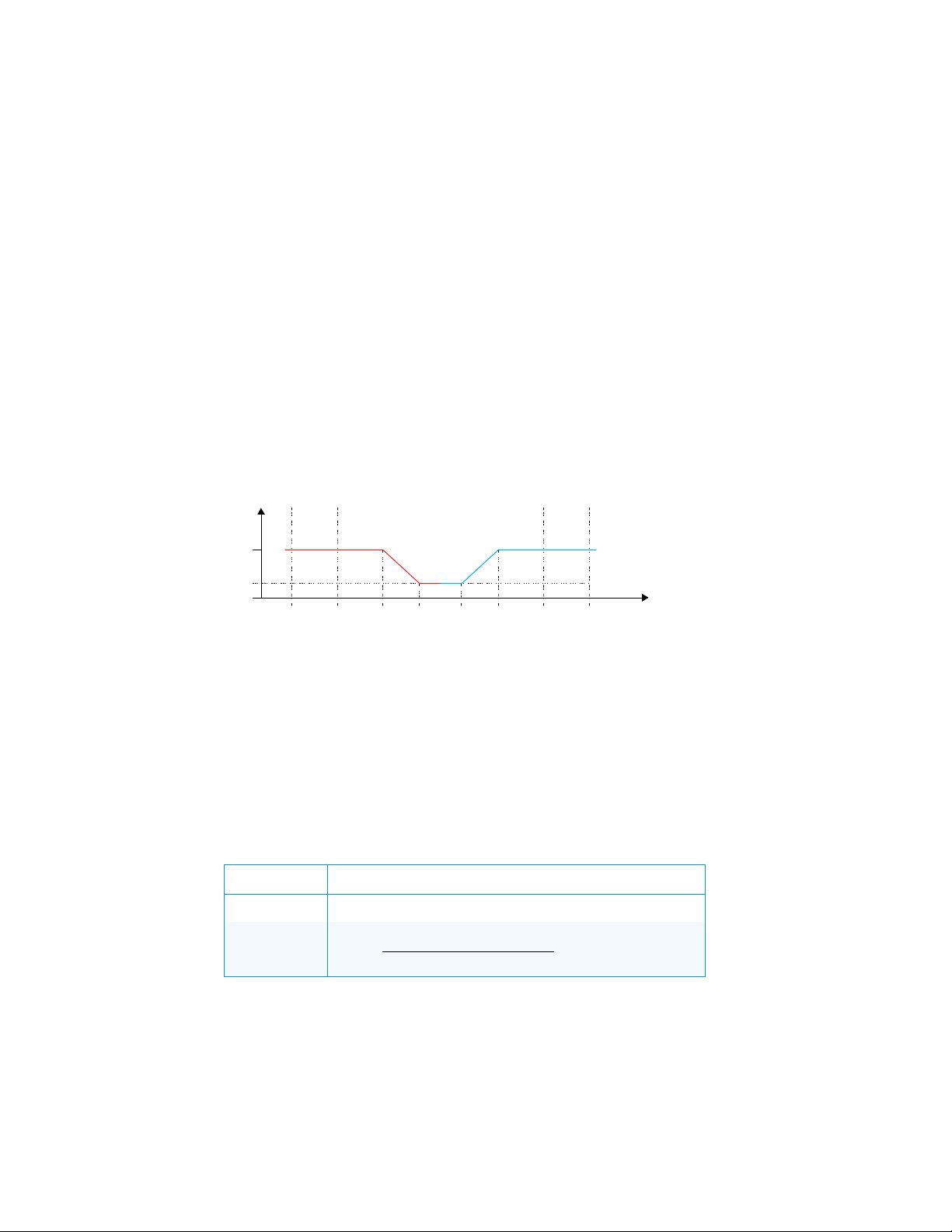
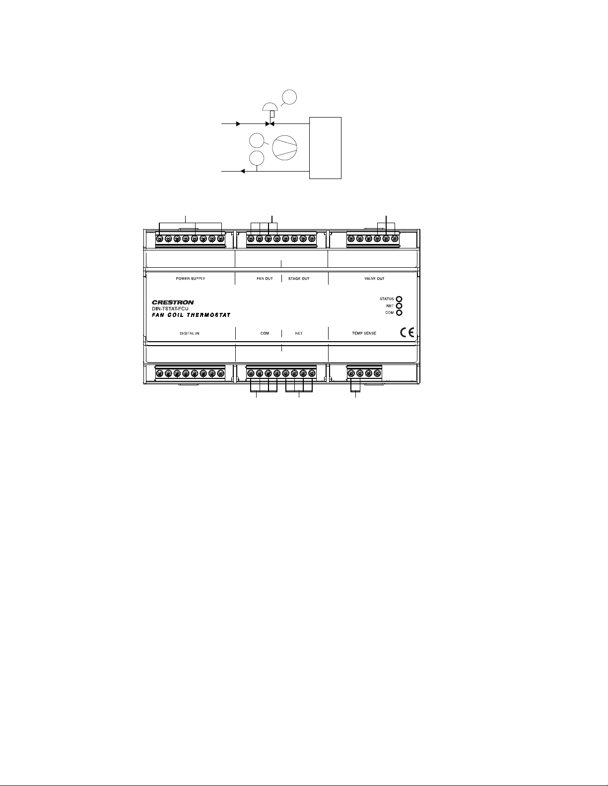
Modulated 0-10 Vac Valve
This device is designed for use with 2-pipe, 3-speed FCU with a 0-10 Vac modulated valve.
In this case, the valve performs regulation in the ∆T vicinity of set point. The valve opens and
closes according to the graph below. The valve is controlled using 0-10 Vac analog output.
For details on controlling the fan speed, refer to the “Fan Speed Control” section.
Valve Position according to Room Temperature
SpH – Set point for heating
SpC – Set point for cooling
Y – Valve position (0 close, 100 fully open)
Y
– Minimum position of valve when set point is reached
min
T – Room temperature
∆T – Step of temperature difference
The following table explains the connection between regulation parameters from the
diagram and user-settable parameters.
Regulation Parameters for Type 1 FCU
PARAMETER EXPLANATION
Y
min
min
8 • DIN-TSTAT-FCU: DIN-Rail Fan-Coil Thermostat Setup and Commissioning Guide – DOC. 8207A
Page 13
NTC
1
Fan
1
CV
1
WS
WR
POWER SUPPLY:
230 Vac power input for
line, neutral, and earth
VALVE OUT:
24 Vac power and 0-10 Vac
control to the valve
FAN OUT:
230 Vac max fan power
in and fan control out
STA
TUS
NET
COM
DIN
-
TS
TAT
-FCU
TEMP SENSE
DIGI
TAL IN
COM
VA
LVE OUT
POWER SUPP
LY
S
TAGE OUT
FAN OUT
NET
LLL
L 1FLFMFHNCL2ST1
ST2
OP
24V
CL
24V
0-10
G
E
NC
NNN
CDI
DI3
CDI
TS1GTS2
G
DI0
CDI
DI1
CDI
DI2
YZG
EPABG24
COM:
To the
room
controller
NET:
To the
control
system
TEMP SENSE:
From the
temperature
sensor
Wiring Diagram
Setup and Commissioning Guide – DOC. 8207A DIN-TSTAT-FCU: DIN-Rail Fan-Coil Thermostat • 9
Page 14
∆T
∆T = × 0.5 °C
Y
=
1000
× 100%
= ×
1000 −
1000
= ×
1000 −
1000
Y (%)
T (˚C)
Sp-3∆T
Sp+3∆T
Sp-2∆T
Sp+2∆T
Sp-∆T
Sp+∆T
SpH
SpC
100
Ymin
0
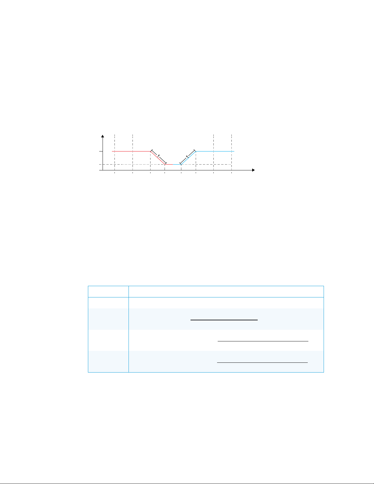
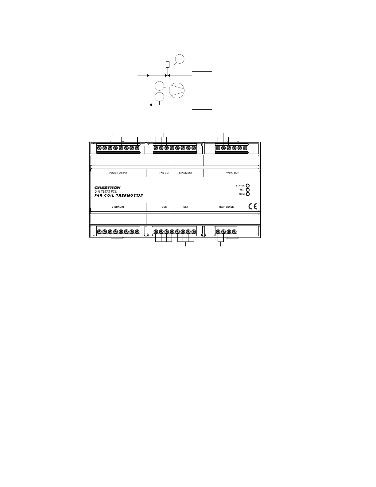
Modulated OP-CL 24 Vac Valve
This device is designed for use with a 2-pipe, 3-speed FCU with 24 Vac common open or
close valve.
In this case, the valve performs regulation in the ∆T vicinity of set point; the valve opens and
closes at the rate of its defined time, according to the graph below.
Periodically, the valve is forced to the fully open position to eliminate accumulated error. The
error correction period is defined by Reset valve error interval parameter.
For details on controlling the fan speed, refer to the “Fan Speed Control” section.
Valve Position according to Room Temperature
SpH – Set point for heating
SpC – Set point for cooling
Y – Valve position (0 close, 100 fully open)
Y
– Minimum position of valve when set point is reached
min
T – Room temperature
∆T – Step of temperature difference
t - Time for valve to reach open/close position
The following table explains the connection between regulation parameters from the
diagram and user-settable parameters.
Regulation Parameters for Type 2 FCU
PARAMETER EXPLANATION
Y
min
min
t when valve
is opening
t when valve
is closing
10 • DIN-TSTAT-FCU: DIN-Rail Fan-Coil Thermostat Setup and Commissioning Guide – DOC. 8207A
Page 15
NTC
1
Fan
1
CV
1
S
WS
WR
COM:
To the
room
controller
NET:
To the
control
system
TEMP SENSE:
From the
temperature
sensor
POWER SUPPLY:
230 Vac power input for
line, neutral, and earth
VALVE OUT:
24 Vac out and solid state
switch control to valve
FAN OUT:
230 Vac max fan power
in and fan control out
STA
TUS
NET
COM
DIN-TS
TAT-FCU
TEMP SENSEDIGIT
AL IN COM
V
ALVE OUTPOWER SUPP
LY
STAGE OUT
FAN OUT
NET
L
L
L
L 1
FL
FM
FH
NC
L2
ST1
ST2
OP
24VCL24V
0-10
G
E
NC
N
N
N
CDI
DI3
CDI
TS1GTS2
G
DI0
CDI
DI1
CDI
DI2
YZG
EP
ABG
24
Wiring Diagram
Setup and Commissioning Guide – DOC. 8207A DIN-TSTAT-FCU: DIN-Rail Fan-Coil Thermostat • 11
Page 16
∆T
∆T = × 0.5 °C
Y
=
1000
× 100%
T (˚C)
t (time)
Sp
∆T* Ymin
0
0
t (time)
100
valve %
T (˚C)
t (time)
Sp
∆T* Ymin
0
0
t (time)
100
valve %
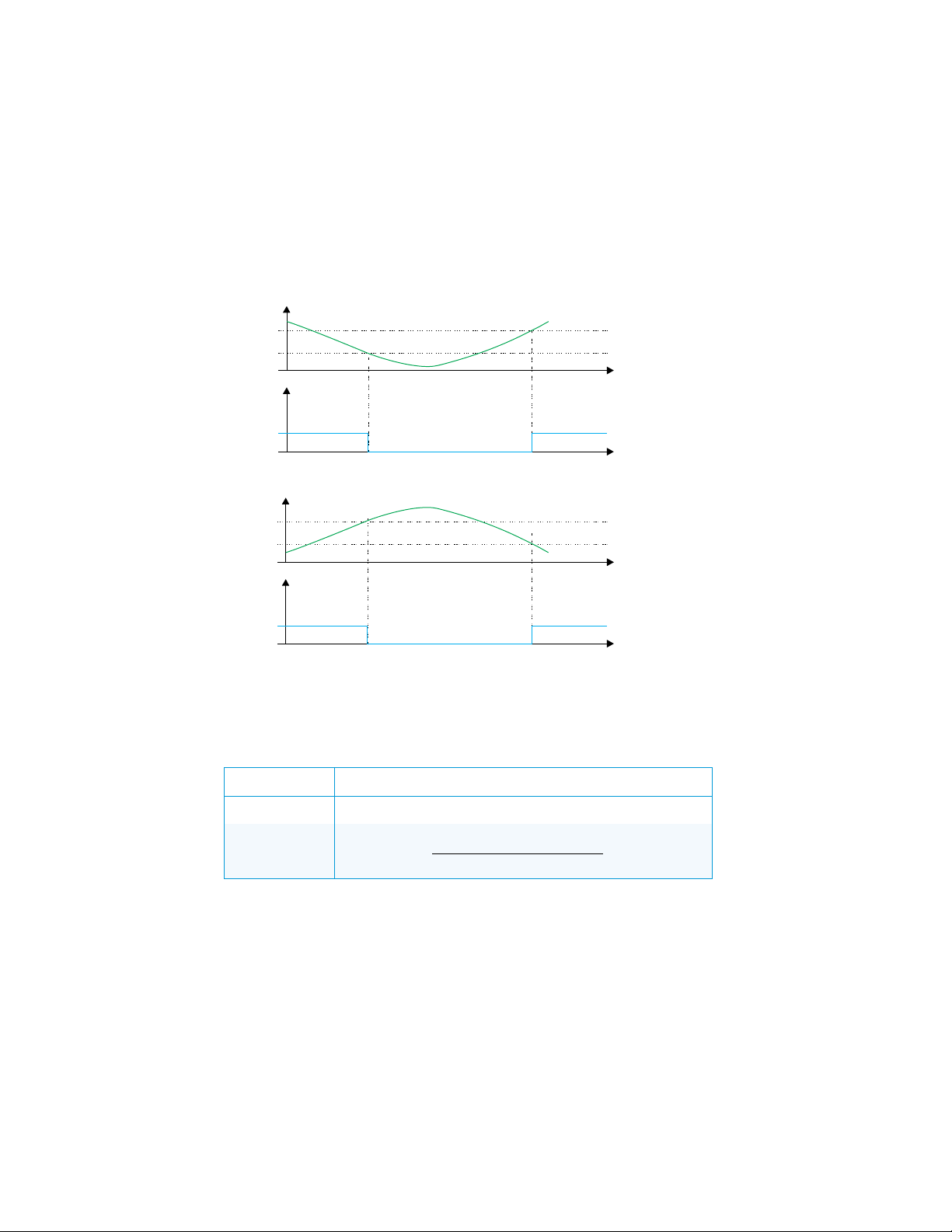
Spring-loaded 24 Vac Valve
This device is designed for use with a 2-pipe, 3-speed FCU with spring-loaded 24 Vac
valve.
In this case, the valve operates as an on and off valve. The valve value is calculated
according to room temperature, as shown in the graphs below. The valve is controlled using
one triac (Valve open).
For details on controlling the fan speed, refer to the “Fan Speed Control” section.
Valve Position according to Room Temperature - Cooling
Valve Position according to Room Temperature - Heating
12 • DIN-TSTAT-FCU: DIN-Rail Fan-Coil Thermostat Setup and Commissioning Guide – DOC. 8207A
∆T* Y
– temperature when valve open
min
The following table explains the connection between regulation parameters from the
diagram and user-settable parameters.
Regulation Parameters for Type 3 FCU
PARAMETER EXPLANATION
Y
min
min
Page 17

NTC
1
Fan
1
CV
1
WS
WR
POWER SUPPLY:
230 Vac power input for
line, neutral, and earth
VALVE OUT:
24 Vac power out and solid
state switch control to the valve
FAN OUT:
230 Vac max fan power
in and fan control out
STATUS
NET
COM
DIN
-TSTA
T-FCU
TEMP SENSEDIGI
TAL IN COM
V
ALVE OUTPOWER SUPP
LY S
TAGE OUTF
AN OUT
NET
LLL
L 1FLFMFHNCL2ST1
ST2
OP
24V
CL
24V
0-10
G
ENCNNN
CDI
DI3
CDI
TS1GTS2
G
DI0
CDI
DI1
CDI
DI2
YZG
EP
ABG
24
COM:
To the
room
controller
NET:
To the
control
system
TEMP SENSE:
From the
temperature
sensor
Wiring diagram
Setup and Commissioning Guide – DOC. 8207A DIN-TSTAT-FCU: DIN-Rail Fan-Coil Thermostat • 13
Page 18

∆T = × 0.5 °C
Y
=
1000
× 100%
= ×
1000 −
1000
= ×
1000 −
1000
Y (%)
T (˚C)
Sp-3∆T
Sp+3∆T
Sp-2∆T
Sp+2∆T
Sp-∆T
Sp+∆T
SpH
SpC
100
Ymin
0
Modulated OP-CL 230 Vac Valve
This device is designed for use with a 2-pipe, 3-speed FCU with 230 Vac common open or
close valve.
In this case, the valve performs regulation in the ∆T vicinity of set point; the valve opens and
closes at the rate of its defined time, according to the graph below.
Periodically, the valve is forced to the fully open position to eliminate accumulated error.
Error annulation period is defined by Reset valve error interval parameter.
For details on controlling the fan speed, refer to the “Fan Speed Control” section.
Valve Position according to Room Temperature
SpH – Set point for heating
SpC – Set point for cooling
Y – Valve position (0 close, 100 fully open)
Y
– Minimum position of valve when set point is reached
min
T – Room temperature
∆T – Step of temperature difference (∆T=N*0.5 °C, N is settable parameter)
t - Time for the valve to reach full open/close position
This table explains the connection between regulation parameters from the diagram and
user-settable parameters.
Regulation Parameters for Type 4 FCU
PARAMETER EXPLANATION
∆T
Ymin
t when valve
is opening
t when valve
is closing
min
14 • DIN-TSTAT-FCU: DIN-Rail Fan-Coil Thermostat Setup and Commissioning Guide – DOC. 8207A
Page 19

NTC
1
Fan
1
CV
1
S
WS
WR
POWER SUPPLY:
230 Vac power input for
line, neutral, and earth
STAGE OUT:
230 Vac max power for open
and close control to the valve
FAN OUT:
230 Vac max fan power
in and fan control out
STATUS
NET
COM
DIN-TSTAT-FCU
TEMP SENSEDIGITAL I N COM
VALVE OUTPOWER SUPPLY STAGE OUTFAN OUT
NET
LLL
L 1FLFMFHNCL2ST1
ST2
OP
24VCL24V
0-10
G
ENCNNN
CDI
DI3
CDI
TS1GTS2
G
DI0
CDI
DI1
CDI
DI2
YZG
EPAB
G
24
COM:
To the
room
controller
NET:
To the
control
system
TEMP SENSE:
From the
temperature
sensor
Wiring Diagram
Setup and Commissioning Guide – DOC. 8207A DIN-TSTAT-FCU: DIN-Rail Fan-Coil Thermostat • 15
Page 20

∆T = × 0.5 °C
Y
=
1000
× 100%
T (˚C)
t (time)
Sp
∆T* Ymin
0
0
t (time)
100
valve %
T (˚C)
t (time)
Sp
∆T* Ymin
0
0
t (time)
100
valve %
Spring-loaded 230 Vac Valve
This device is designed for use with a 2-pipe, 3-speed FCU with spring-loaded 230 Vac
valve.
In this case, the valve operates as an on and off valve. The valve value is calculated
according to room temperature, as shown in the graphs below.
The valve is controlled using one relay (Valve open).
For details on controlling the fan speed, refer to the “Fan Speed Control” section.
Valve Position according to Room Temperature - Cooling
Valve Position according to Room Temperature - Heating
Sp – set point
∆T* Y
– temperature when valve is open
min
The following table explains the connection between regulation parameters from the
diagram and user-settable parameters.
Regulation Parameters for Type 5 FCU
PARAMETER EXPLANATION
∆T
Ymin
min
16 • DIN-TSTAT-FCU: DIN-Rail Fan-Coil Thermostat Setup and Commissioning Guide – DOC. 8207A
Page 21

NTC
1
Fan
1
CV
1
WS
WR
POWER SUPPLY:
230 Vac power input for
line, neutral, and earth
FAN OUT:
230 Vac max fan power
in and fan control out
STA
TUS
NET
COM
DIN-TS
TAT-FCU
TEMP SENSEDIGIT
AL IN COM
VA
LVE OUTPOWER SUPP
LY
S
TAGE OUTF
AN OUT
NET
L
L
L
L 1
FL
FM
FH
NC
L2
ST1
ST2
OP
24VCL24V
0-10
G
E
NC
N
N
N
CDI
DI3
CDI
TS1GTS2
G
DI0
CDI
DI1
CDI
DI2
YZG
EPAB
G
24
STAGE OUT:
230 Vac max power for
open control to the valve
COM:
To the
room
controller
NET:
To the
control
system
TEMP SENSE:
From the
temperature
sensor
Wiring Diagram
Setup and Commissioning Guide – DOC. 8207A DIN-TSTAT-FCU: DIN-Rail Fan-Coil Thermostat • 17
Page 22

T (˚C)
t
∆T
∆T/2
Sp
S1
S2
0
0
t
valve %
1-2 Stage Direct-expansion System
This device is designed for use with a 3-speed, direct-expansion system with compressor
control - cooling only.
In this case, a compressor is controlled instead of a valve. The compressor state for stage
one and stage two is determined by the room temperature. The compressor is controlled
using two relays (Stg 1 – stage 1, Stg 2 – stage 2).
The diagram of working compressor according to room temperature is shown in the graph
below.
For details on controlling the fan speed, refer to the “Fan Speed Control” section.
Diagram of Working Compressor according to Room Temperature
Sp- set point
∆T – Step of temperature difference (∆T=N*0.5 °C, N is settable parameter)
S2 – Stage 2 ON
S1 – Stage 1 ON
18 • DIN-TSTAT-FCU: DIN-Rail Fan-Coil Thermostat Setup and Commissioning Guide – DOC. 8207A
Page 23

NTC
1
Fan
1
AS
AR
POWER SUPPLY:
230 Vac power input for
line, neutral, and earth
FAN OUT:
230 Vac max fan power
in and fan control out
STATUS
NET
COM
DIN-TSTAT-FCU
TEMP SENSEDIGITAL IN COM
VALVE OUTPOWER SUPP
L
Y S
TAGE OUT
F
AN OUT
NET
LLL
L 1FLFMFHNCL2ST1
ST2
OP
24V
CL
24V
0-10
G
ENCNNN
CDI
DI3
CDI
TS1GTS2
G
DI0
CDI
DI1
CDI
DI2
YZG
EPABG24
STAGE OUT:
230 Vac max power for Stage 1 and
Stage 2 control to the compressor
COM:
To the
room
controller
NET:
To the
control
system
TEMP SENSE:
From the
temperature
sensor
Wiring Diagram
Setup and Commissioning Guide – DOC. 8207A DIN-TSTAT-FCU: DIN-Rail Fan-Coil Thermostat • 19
Page 24

High
Fan Speed
Medium
Low
T (˚C)
Sp-3∆T Sp+3∆TSp-2∆T
Sp+2∆TSp-∆T
Sp+∆TSpH SpC
Fan Speed Control
This device is designed for all configuration, the fan shifts to low, medium, and high speed
based on room temperature. When room temperature reaches its set point, if parameter
Fan speed OFF enable is set to 1, the fan turns down; otherwise it remains in low.
If fan speed is forced, it constantly runs at the selected speed.
The diagram below shows the fan speed according to room temperature and operating
mode.
Fan Speed according to Room Temperature
SpH – Set point for heating
SpC – Set point for cooling
T – Room temperature
∆T – Step of temperature difference (∆T = × 0.5 °C)
20 • DIN-TSTAT-FCU: DIN-Rail Fan-Coil Thermostat Setup and Commissioning Guide – DOC. 8207A
Page 25

DIGITAL IN:
From the window
switch, door switch, or
occupancy sensor
POWER SUPPLY:
Power input for line,
neutral, and earth
STATUS
NET
COM
DIN-TSTAT-FCU
TEMP SENSEDIGITAL IN CO M
VALVE OUTPOWER SUPPLY STAGE OUTFAN OUT
NET
LLL
L 1FLFMFHNCL2ST1
ST2
OP
24VCL24V
0-10
G
ENCNNN
CDI
DI3
CDI
TS1GTS2
G
DI0
CDI
DI1
CDI
DI2
YZG
EPABG24
COM:
To the
room
controller
NET:
To the
control
system
Alarms
The device has four digital inputs reserved for external alarm signals. Their usage is optional
and adjustable by device configuration parameters. Each of the four alarm inputs has three
adjustable parameters available:
• Alarm X enable – Determines if the alarm input is used
• Alarm X polarity – Alarm is active if the incoming input signal corresponds to the set
polarity
• Alarm 1 delay – Time interval from the alarm input signal activation to the activation
of the alarm state
Alarm inputs are used for accepting signals from window/door sensors, condensation
canister sensor, PIR sensors, etc.
If enabled and activated, the alarm blocks the device outputs for fan speed (fan speed will
be set to 0) and closes the valve by forcing valve outputs (different outputs depending on
device configuration type). If the delay time is set, alarm activation or deactivation is
postponed by alarm delay time.
The wiring diagram below shows an example where three alarm inputs are used.
Alarms Wiring Example
Temperature Probes
DIN-TSTAT-FCU device has two resistance measuring inputs for NTC probes. First input is
used for room temperature measurement. The second input can be used for water
temperature monitoring.
For the best results, use 20K NTC probes.
Setup and Commissioning Guide – DOC. 8207A DIN-TSTAT-FCU: DIN-Rail Fan-Coil Thermostat • 21
Page 26

Supported NTC Probes
PROBE TYPE RANGE [OC] TEMPERATURE PROBE 1/2
NTC 20K 0 – 100 1
NTC 10K 0 – 100 2
NTC 12K 0 – 100 3
NTC 15K 0 – 100 4
Cresnet® Communications
The DIN-TSTAT-FCU primarily communicates using the NET port. The NET port has four
pins marked as 24, Y, Z, G, where 24 is 24 V input, Y and Z are + and – signal lines, and G
is ground.
Through the Cresnet network, a user can do the following:
• Change the temperature set point either by sending a new value or by sending raise
and lower commands
TYPE PARAMETER VALUE
• Set the desired fan speed mode (low, medium, high, or auto)
• Set the operating mode (cooling, heating, or off)
• Monitor the current temperature set point
• Monitor the currently active operating mode
• Monitor the currently active fan speed
• Monitor the status of binary inputs
• Monitor the measured temperatures
Commands issued using the Cresnet port are also reported back through the Modbus port.
The last received command is considered valid. The Cresnet network and local room
display unit are both informed about the last change.
Port
The device can operate using only power supplied from the Cresnet network, but in that
case, I/O resources are not operational and a main power supply error is reported. When
operating from network power supply, the device consumes 0.5 W.
Communication
The device is reported as a DIN-TSTAT-FCU on the Cresnet network. The serial number is
the same as serial number on the device label.
While Cresnet communication is active, the NET LED is ON.
22 • DIN-TSTAT-FCU: DIN-Rail Fan-Coil Thermostat Setup and Commissioning Guide – DOC. 8207A
Page 27

Joins
The device input and output joins are listed in the tables below.
Input Joins
JOIN TYPE JOIN NAME JOIN NUMBER
Digital Raise_Setpoint 1
Digital Lower_Set point 2
Digital Mode_Heat 3
Digital Mode_Cool 4
Digital Mode_Off 6
Digital Fan_High 9
Digital Fan_Med 10
Digital Fan_Low 11
Digital Fan_Auto 12
Analog Setpoint 1
Output Joins
JOIN TYPE JOIN NAME JOIN NUMBER
Digital Mode_Heat_FB 3
Digital Mode_Cool_FB 4
Digital Mode_Off_FB 6
Digital Is_Cooling_FB 7
Digital Is_Heating_FB 8
Digital Fan_High_FB 9
(continued on the following page)
Setup and Commissioning Guide – DOC. 8207A DIN-TSTAT-FCU: DIN-Rail Fan-Coil Thermostat • 23
Page 28

Output Joins (continued)
JOIN TYPE JOIN NAME JOIN NUMBER
Digital Fan_Med_FB 10
Digital Fan_Low_FB 11
Digital Fan_Auto_FB 12
Digital Input_1_FB 13
Digital Input_2_FB 14
Digital Input_3_FB 15
Digital Input_4_FB 16
Analog Setpoint_FB 1
Analog Temperature_1_FB 2
Analog Temperature_2_FB 3
Analog MinHeatSetpoint_FB 4
Analog MaxHeatSetpoint_FB 5
Analog MinCoolSetpoint_FB 6
Analog MaxCoolSetpoint_FB 7
Analog FCU_Type 11
Light and Poll
Light and Poll (LP) is a mechanism that allows a device to identify itself through physical
input from a user. This helps identify devices in their physical location, as well as reduce the
chance of communicating with the wrong device. LP works in the following manner:
1. A Start Light and Poll (SLP) command is sent from the control system to
DIN-TSTAT-FCU.
2. The device blinks its NET LED to indicate that it is in Light and Poll mode.
3. Press the NET button to acknowledge the SLP command. This ends the Light and
Poll procedure by sending an End Light and Poll (ELP) command.
24 • DIN-TSTAT-FCU: DIN-Rail Fan-Coil Thermostat Setup and Commissioning Guide – DOC. 8207A
Page 29

Press the Pushbutton to Acknowledge SLP
AUX Port
An auxiliary RS-485 port supports the Modbus RTU protocol. The device is master on
Modbus network. This port is used for connecting to a local room display unit. The local
room display unit enables user to do the following:
• Set the temperature set point
• Set the desired fan speed mode (low, medium, high, or auto)
• Set the operating mode (cooling, heating, or off)
• Monitor the current temperature set point
• Monitor the currently active operating mode
• Monitor the currently active fan speed
• Monitor the measured room temperature
Commands from the auxiliary port can be received concurrently with commands from the
NET port. The last received command is considered valid. The control system and local
room display unit are both informed about the last change.
Communication parameters are settable through user registers.
Port
The auxiliary port has four pins marked EP, A, B, G, where EP is external power supply, A
and B are + and – communication signals lines, and G is ground.
Setup and Commissioning Guide – DOC. 8207A DIN-TSTAT-FCU: DIN-Rail Fan-Coil Thermostat • 25
Page 30

The DIN-TSTAT-FUC can supply power to other devices on the Modbus network. Supply
voltage is 20 Vdc and the maximum output current is 100 mA.
Communication
The device is preprogrammed to read and write particular values to and from local room
display.
Modbus reads:
• Temperature set point
• Desired fan speed mode
• Desired operating mode
Modbus writes:
• Active temperature set point
• Active fan speed mode
• Active operating mode
• Current room temperature
• Minimum set point value
• Maximum set point value
Write Multiple Registers command is used for register write and Read Holding Registers
command is used for register read. The registers are written on value change while read is
performed on best effort.
While communication is active, the COM LED blinks. If communication is error-free COM
LED blinks fast, and each error will introduce a delay of 1s between the LED flashes.
26 • DIN-TSTAT-FCU: DIN-Rail Fan-Coil Thermostat Setup and Commissioning Guide – DOC. 8207A
Page 31

Registers
Registers that read and write from the local room display are shown below.
Modbus Read/Write Registers
USB Port
REGISTER
NAME
Set point Set point min – Set
Fan speed
command
Mode
command
Air
temperature
Set point min 0 – 1000 Write Temperature is in format oC x 10
Set point max 0 – 1000 Write Temperature is in format oC x 10
RANGE READ/WRITE NOTE
Read/Write Temperature is in format oC x 10
point max
1 – 4 Read/Write 1: Lo; 2: Med; 3: Hi; 4: Auto
0 – 2 Read/Write 0: OFF; 1: Cooling; 2: Heating
0 – 1000 Write Temperature is in format oC x 10
Parameters
For communication with the local room display unit to be established, correct parameters
must be written to communication registers. Refer to “Device Parameters” on page 4 for
details. After parameters are set, reboot the device for changes to take effect.
The USB port is used for device commissioning and software updates including operating
system and firmware updates. USB connector type on the DIN-TSTAT-FCU is Mini-B.
NOTE: It may be necessary to install a USB driver to be able to communicate with the
DIN-TSTAT-FCU over USB.
Accessing USB Port
USB port is located under the cover of the DIN-TSTAT-FCU. To open the cover, use a
2 mm wide flat screwdriver to gently pry the cover open using the four slots that are marked
below.
Setup and Commissioning Guide – DOC. 8207A DIN-TSTAT-FCU: DIN-Rail Fan-Coil Thermostat • 27
Page 32

Releasing the Lid
Accessing the USB Port
28 • DIN-TSTAT-FCU: DIN-Rail Fan-Coil Thermostat Setup and Commissioning Guide – DOC. 8207A
Page 33

USB Driver Installation Procedure
NOTE: USB driver installation procedure is necessary only if the USB driver is not installed
automatically after the USB cable is inserted.
Before the USB driver is installed, please install DIN-TSTAT-FCU Configuration Tool.
The USB driver installation procedure explained in this section is for Windows
system but is similar to other Windows versions.
To install the USB driver, follow these steps:
1. Connect the DIN-TSTAT-FCU to the PC using a USB cable.
®
7 operating
2. Open the
Device Manager
window.
3. Click the DIN-TSTAT-FCU with the missing driver.
4. Click on the
Update Driver
shortcut icon.
5. Click “Browse my computer for driver software.”
Setup and Commissioning Guide – DOC. 8207A DIN-TSTAT-FCU: DIN-Rail Fan-Coil Thermostat • 29
Page 34

6. Browse to the location that the DIN-TSTAT-FCU Configuration Tool is installed and
then click
Next. The default location is
C:\Program Files (x86)\Crestron\DIN-TSTAT-FCU Configuration Tool.
7. If the
Windows Security
anyway
.
window appears, click
Install this driver software
30 • DIN-TSTAT-FCU: DIN-Rail Fan-Coil Thermostat Setup and Commissioning Guide – DOC. 8207A
Page 35

8. After installation is complete, a popup window indicating installation success
appears.
9. Check that the device has appeared in the
number associated with device.
Device Manager
list and note COM
Install the DIN-TSTAT-FCU Configuration Tool
To install the DIN-TSTAT Configuration Tool, do the following:
1. Double-click the DIN-TSTAT-FCU Configuration Tool.exe file to begin installation.
Setup and Commissioning Guide – DOC. 8207A DIN-TSTAT-FCU: DIN-Rail Fan-Coil Thermostat • 31
Page 36

2. Enter the installation destination in the “Setup -Select Destination Location”
window. The default installation destination
“C:\Program Files (x86)\Crestron\DIN-TSTAT-FCU Configuration Tool”. Click
Next.
3. In the “Setup – Select Start Menu Folder,” set the installation options for creating a
shortcut for the configuration tool in the Start Menu folder. Click
Next.
32 • DIN-TSTAT-FCU: DIN-Rail Fan-Coil Thermostat Setup and Commissioning Guide – DOC. 8207A
Page 37

4. In the “Setup – Select Additional Tasks” window, select or clear the Create a
desktop shortcut check box to create a shortcut to the DIN-TSTAT-FCU
Configuration tool on your desktop. Click
Next.
5. The DIN-TSTAT-FCU Configuration tool is installed. Upon completion, a summary
window is displayed gives the option to start the application. Select or clear the
Setup and Commissioning Guide – DOC. 8207A DIN-TSTAT-FCU: DIN-Rail Fan-Coil Thermostat • 33
Page 38

Launch DIN-TSTAT-FCU Configuration Tool check box to open the program after
exiting the installation process. Click
Finish to exit the installation process.
Using the DIN-TSTAT-FCU Configuration Tool
The DIN-TSTAT-FCU Configuration Tool sets the parameters for the DIN-TSTAT-FCU.
Menu Overview
The menu bar contains File, ComPort, Device, and Help menus that provide access to
various setup and operation features.
File Menu
The File menu contains New, Open, Save and Save As options.
New – creates new tables with the default parameters for Regulation and Alarms. It
populates default values for the the Valve/Compressor table based on the FCU type list.
Open – opens a previously saved value configuration from an xml file.
34 • DIN-TSTAT-FCU: DIN-Rail Fan-Coil Thermostat Setup and Commissioning Guide – DOC. 8207A
Page 39

Save – saves the current values from the tables inside an xml file. If the current file is the
default-parameters.xml file, which cannot be overwritten, the program prompts a file
selection dialog so the user can select a new file to save in.
Save As – opens a file save dialog that lets the user choose a save location for the xml
table.
ComPort Menu
The ComPort menu contains a Settings option.
Settings Menu
Click the Scan Ports button to identify and list all used ports in the system. Select the port
that the DIN-TSTAT-FCU uses to communicate from the drop-down list.
Click OK to save the settings and exit the menu. Click Cancel to discard the settings and
exit.
Device Menu
The Device menu contains Firmware Update, OS Update, Device Info, Restore, and Restart
options.
Setup and Commissioning Guide – DOC. 8207A DIN-TSTAT-FCU: DIN-Rail Fan-Coil Thermostat • 35
Page 40

Firmware Update
The “Firmware Update” window displays device firmware information and allows new
firmware to be loaded to the device.
To load firmware to the DIN-TSTAT-FCU, do the following:
OS Update
The “OS Update” window allows an updated OS to be loaded to the DIN-TSTAT-FCU. The
information about the current OS in the device is displayed in the “OS Info” section of the
window.
OS Update Window
1. Click the Select file button and select the firmware file to be loaded. The Firmware
information is displayed in the “File” section of the “Firmware Update” window.
2. Click the Update button to load the firmware onto the DIN-TSTAT-FCU.
To update the OS of the DIN-TSTAT-FCU, do the following:
1. Click the Select file button to select and load the updated OS.
36 • DIN-TSTAT-FCU: DIN-Rail Fan-Coil Thermostat Setup and Commissioning Guide – DOC. 8207A
Page 41

2. In the pop-up dialog, click Yes to accept that the procedure cannot be terminated
after proceeding. The device is placed into OS Flash mode and all LEDs on the
DIN-TSTAT-FCU turn off.
CAUTION: The OS update procedure cannot be aborted after clicking Yes. The
remaining procedure must be completed and an OS must be flashed to the device.
3. Turn off power to the POWER SUPPLY and NET port.
4. Disconnect the USB cable from the DIN-TSTAT-FCU, and then reconnect the USB
cable.
NOTE: The USB cable must be removed and then reinserted into the
DIN-TSTAT-FCU before continuing.
5. Click Scan ports, and then select the port with which the DIN-TSTAT-FCU is
associated.
6. Click Next.
7. Click Update to start the OS update process.
8. When prompted, disconnect the USB cable from the DIN-TSTAT-FCU, and then
reconnect the USB cable. The LED lights when the USB cable is reconnected.
Setup and Commissioning Guide – DOC. 8207A DIN-TSTAT-FCU: DIN-Rail Fan-Coil Thermostat • 37
Page 42

NOTE: The USB cable must be removed and then reinserted into the
DIN-TSTAT-FCU before continuing.
9. Restore power to the POWER SUPPLY and NET port.
Device Info
The “Device Info” window displays device information such as Device Info, Firmware Info,
and OS Info.
Restore
Device recovery is available only when an OS Update fails while a new OS is being written or
verified. It allows the DIN-TSTAT-FCU to recover to the last known working OS.
1. Turn off power to the POWER SUPPLY and NET ports.
2. Disconnect the USB cable from the DIN-TSTAT-FCU, and then reconnect the USB
cable.
NOTE: The USB cable must be removed and then reinserted into the
DIN-TSTAT-FCU before continuing.
3. Press Scan and then select the port with which the DIN-TSTAT-FCU is associated.
38 • DIN-TSTAT-FCU: DIN-Rail Fan-Coil Thermostat Setup and Commissioning Guide – DOC. 8207A
Page 43

4. Click Next.
5. Click Recover.
6. When prompted, disconnect the USB cable from the DIN-TSTAT-FCU, and then
reconnect the USB cable. The LED lights when the USB cable is reconnected.
NOTE: The USB cable must be removed and then reinserted into the
DIN-TSTAT-FCU before continuing.
7. Restore power to the POWER SUPPLY and NET port.
8. Click Finish.
Restart
The “Restart” window allows the device to be restarted. When restarted, the
DIN-TSTAT-FCU is put into idle state, and then put into a normal operating state.
Help Menu
The Help menu contains About, DIN-TSTAT-FCU specifications, and Program Help options.
About - The “About” window displays the version number of the DIN-TSTAT-FCU
Configuration Tool and copyright information.
Setup and Commissioning Guide – DOC. 8207A DIN-TSTAT-FCU: DIN-Rail Fan-Coil Thermostat • 39
Page 44

DIN-TSTAT-FCU specifications - The “DIN-TSTAT-FCU specifications” window displays a
PDF with the specifications of the device.
Program Help – The “Program Help” window displays the user manual for the program.
Configure the DIN-TSTAT-FCU
NOTE: When the DIN-TSTAT-FCU Configuration Tool is run for the first time, it searches for
available ports. If only one port is discovered, it connects to the DIN-TSTAT-FCU associated
with that port. Upon subsequent starts, it loads the port used during the last session.
NOTE: Configuration save is done automatically upon changing the working file or
changing the port, as well as upon closing the application.
Toolbar Bar
The toolbar contains Write, Read, and Set Default buttons.
Write – writes the values from the table to the DIN-TSTAT-FCU.
Read – reads the values from the DIN-TSTAT-FCU and populates them into the tables.
Set Default – sets the values in tables to the default values.
Status Bar
The toolbar contains Device, Parameters file, and Port information.
Device – displays the connected device.
Parameters file – displays the name of the active table that is being edited.
Port – displays the port of the connected DIN-TSTAT-FCU.
Main Screen
The main screen displays the FCU Type, TABLE Name and Expander, and Tables
information.
FCU Type List
The FCU type determines the content and the name of the Valve/Compressor parameters
table. When an FCU type is selected, the Valve/Compressor parameters table is populated
with default values. Existing values are erased.
40 • DIN-TSTAT-FCU: DIN-Rail Fan-Coil Thermostat Setup and Commissioning Guide – DOC. 8207A
Page 45

Table Name and Expander
The Table Name and Expander displays the name of the table. Click the “+” or “-” button to
show or hide that table.
Tables
Every configuration file contains three tables: Regulation parameters, Alarm parameters,
and Valve/Compressor parameters. Each table contains the following parameters:
Name – user friendly name of the parameter.
Value – only editable field (shown also by the white column color) that represents the value
that parameter will have on the device.
Unit – shows what the parameter represents in the context of the device.
Range – shows the minimum and maximum values the value can have.
Description – shows a detailed description of what that parameter represents. This is also
available as a tooltip for that row.
Configuration Table Example
Monitoring
The monitoring feature allows dynamic monitoring of a set of values from the device.
Monitor – activates the monitoring process for the indicated set of values. Other functions
of the program are blocked.
Stop - Stops the monitoring process. All functionalities are enabled.
Monitoring table:
Name – the name of the variable.
Value – the read value from the device.
Setup and Commissioning Guide – DOC. 8207A DIN-TSTAT-FCU: DIN-Rail Fan-Coil Thermostat • 41
Page 46

Unit – the unit of the displayed value.
Description – a short description of the variable.
Monitoring Table Example
The values that are displayed are stored in the monitoring.xml file, which is located in the
“files” folder where the DIN-TSTAT-FCU Commissioning Tool is installed.
Variable Forcing
For certain fields of the monitoring table, it is possible to force values. Enter the numeric or
binary value, and then click
to the previous state, click
Force to force the value. To stop forcing the value and return it
Deforce.
Troubleshooting
Error Code
Using Cresnet, the DIN-TSTAT-FCU can report certain errors. The errors are bit coded in
FCU_type join as presented in the table below.
Error Codes
BIT ERROR DESCRIPTION
15 Parameter error There is an error in parameters stored in flash.
14 Main power supply error The main power supply is off or voltage is below minimum
13 Water temperature error The water temperature is inadequate or the water
12 Probe 1 error The air temperature probe is not connected or is shorted.
11 Probe 2 error The second temperature probe is not connected or is
level.
temperature probe is not functioning. An error is reported
only if water temperature measuring is enabled.
shorted. An error is reported only if second temperature
probe is enabled.
42 • DIN-TSTAT-FCU: DIN-Rail Fan-Coil Thermostat Setup and Commissioning Guide – DOC. 8207A
Page 47

Troubleshooting
The following provides corrective actions for possible trouble situations. If further assistance
is required, please contact a Crestron customer service representative.
DIN-TSTAT-FCU Troubleshooting
TROUBLE POSSIBLE CAUSE(S) ACTION
The LED indicators
are off on power up.
The Cresnet
communication is not
working.
The local room display
unit is off while the
device is turned on.
The communication
with the local room
display unit is not
functioning.
Power is not being
provided to the device.
The device was left in the
OS update mode.
The OS update procedure
was interrupted.
The Cresnet cable is
improperly wired.
There is an error in the
Cresnet network or
master device.
There is a wiring error. Check the room display unit wiring.
The Modbus
communication
parameters are bad.
The register addresses are
bad.
Check the ac and Cresnet wiring.
Use the DIN-TSTAT-FCU Configuration
Tool to perform an OS update
procedure.
Perform the restore procedure if the
Restore option is enabled in the
DIN-TSTAT-FCU Configuration Tool.
Ensure that the Cresnet connection is
properly made.
Using the DIN-TSTAT-FCU Configuration
Tool in Monitoring mode, check the value
of Cresnet status variable (0-no
connection, 1-activity detected, 2connected).
Check the Cresnet wiring.
Check if either main or Cresnet power
supplies are present.
Turn off the device, reconnect the wiring,
and power up the device again.
Using a voltmeter, check if voltage
between the EP and G pins is 20 Vdc.
If the COM LED indicator blinks once per
second, then DIN-TSTAT-FCU is trying
to establish communication but no
response is received. Use the
DIN-TSTAT-FCU Configuration Tool in
Monitoring mode to check if Modbus is
detected.
Reconnect the communication cable.
Check the communication wiring.
Check if the DIN-TSTAT-FCU and Local
room display unit communication
parameters match.
If the COM LED indicator is Off, check
the communication parameters on the
DIN-TSTAT-FCU.
Use Monitoring mode to check the
Modbus parameters error variable.
(Continued on the following page)
Setup and Commissioning Guide – DOC. 8207A DIN-TSTAT-FCU: DIN-Rail Fan-Coil Thermostat • 43
Page 48

DIN-TSTAT-FCU Troubleshooting (continued)
TROUBLE POSSIBLE CAUSE(S) ACTION
The local room display
unit functions are not
working (e.g., fan
speed, mode change,
set point change,
etc.).
The fan is off when the
fan speed is set to 1,
2, or 3.
The fan is always
operating.
Fan does not change
speed.
Communication with the
local room display unit is
not functioning properly.
Commands from Cresnet
are overriding commands
received from AUX port.
The temperature probe
has an incorrect reading.
There is an error in the fan
speed wiring.
There is an error in the
main power supply wiring.
An alarm is active. Correct the issues that are causing the
The water temperature is
inappropriate.
The operating mode is set
to off.
The FCU initialization
function is in progress.
The Fan speed OFF
enable parameter is 0.
Temperature probe 1 is
reading the wrong
temperature.
The time from the last
speed change has not
expired yet.
The wrong operating
mode is active.
If communication is not functional, refer
to the “the communication with the local
room display unit is not functioning”
error.
Check traffic on Cresnet network.
Using the DIN-TSTAT-FCU Configuration
Tool in Monitoring mode, check:
• Temperature probe error flags.
• Water temperature error flag.
• FCU initialization flag.
• Main power supply error flag.
• Alarm statuses.
Using the DIN-TSTAT-FCU Configuration
Tool in Monitoring mode, force fan speed
relay outputs
Check the fan speed wiring.
alarm.
Normal fan operation continues once the
water reaches the desired temperature.
Turn the DIN-TSTAT-FCU on.
Normal fan operation continues after the
initialization process is complete.
Using the DIN-TSTAT-FCU Configuration
Tool, read the Fan speed OFF enable
parameter value.
Using DIN-TSTAT-FCU Configuration
Tool in Monitoring mode, check the
measured Ambient temperature.
Using the DIN-TSTAT-FCU Configuration
Tool, read the fan speed change delay
parameter value, and wait for time equal
to the set value.
Using the DIN-TSTAT-FCU Configuration
Tool in Monitoring mode, check the
Selected mode value.
(continued on the following page)
44 • DIN-TSTAT-FCU: DIN-Rail Fan-Coil Thermostat Setup and Commissioning Guide – DOC. 8207A
Page 49

DIN-TSTAT-FCU Troubleshooting (continued)
TROUBLE POSSIBLE CAUSE(S) ACTION
A valve is off or is
inactive.
There are temperature
probe errors.
The valve output wiring is
incorrect.
An alarm is active. Using the DIN-TSTAT-FCU Configuration
Check the main power supply and the
valve wiring.
Check if the appropriate FCU type is
selected.
Tool in Monitoring mode, check:
• Temperature probe errors.
• The measured temperatures.
• The main power supply.
• The selected operating mode.
• The current alarm states.
• If Type 1 is selected, check the
analog voltage control output
value. Use the forcing option to
set the desired voltage on the
output regardless of current
regulation state.
• If Type 2 or 3 is selected, check
the OP-CL triac output
variables. Use the forcing
option to place outputs in the
desired state regardless of the
current regulation state.
• If Type 4, 5, or 6 is selected,
check Stage 1 or 2 relay output
variables. Use the forcing
option to place the outputs in
the desired state regardless of
the current regulation state.
(continued on the following page)
Setup and Commissioning Guide – DOC. 8207A DIN-TSTAT-FCU: DIN-Rail Fan-Coil Thermostat • 45
Page 50

DIN-TSTAT-FCU Troubleshooting (continued)
TROUBLE POSSIBLE CAUSE(S) ACTION
The valve remains in
the open position.
The alarms are
inactive when they
should be active.
An incorrect operating
mode is selected.
The FCU initialization has
not finished yet.
The water temperature is
inappropriate.
The freeze prevention
function is activated.
There is an error in the
valve output wiring.
There is an error in the
alarm wiring.
There is an error in the
alarm parameters.
Using the DIN-TSTAT-FCU Configuration
Tool in Monitoring mode, check:
• Measured temperatures.
• Selected operating mode.
• Alarm states.
• If Type 1 is selected check
Analog voltage control output
value. Use forcing option to set
desired voltage on output
regardless of regulation state.
• If Type 2 or 3 is selected check
OP-CL triac output variables.
Use forcing option to place
outputs in desired state
regardless of regulation state.
• If Type 4, 5, or 6 is selected,
check Stage 1/2 relay output
variables. Use forcing option to
place outputs in desired state
regardless of regulation state.
If the mode is on and the measured
ambient temperature is lower than 5 °C,
the valve is fully open to prevent freezing.
Check the valve wiring.
Verify that the freeze prevention functions
are operating correctly.
Check the valve output wiring.
Check the alarm wiring.
Using the DIN-TSTAT-FCU Configuration
Tool, verify the alarm polarity and the
delay.
Using the DIN-TSTAT-FCU Configuration
Tool in Monitoring mode, check the
binary input and alarm statuses. Use the
force option to place the input in the
desired state.
(Continued on the following page)
46 • DIN-TSTAT-FCU: DIN-Rail Fan-Coil Thermostat Setup and Commissioning Guide – DOC. 8207A
Page 51

DIN-TSTAT-FCU Troubleshooting (continued)
TROUBLE POSSIBLE CAUSE(S) ACTION
The alarms are
triggered too fast or
too slow.
The alarms are always
active.
There is an error in an
alarm parameter.
There is an error in the
alarm wiring.
There is an error in the
alarm parameters.
Using the DIN-TSTAT-FCU Configuration
Tool, check the selected alarm delay.
Check the alarm wiring.
Using the DIN-TSTAT-FCU Configuration
Tool, check the selected alarm polarity
and the delay.
Using the DIN-TSTAT-FCU Configuration
Tool in Monitoring mode, check the
binary input and the alarm statuses. Use
the force option to place the input in the
desired state.
Setup and Commissioning Guide – DOC. 8207A DIN-TSTAT-FCU: DIN-Rail Fan-Coil Thermostat • 47
Page 52

Crestron Electronics, Inc. Setup and Commissioning Guide – DOC. 8207A
15 Volvo Drive Rockleigh, NJ 07647 (2048992)
Tel: 888.CRESTRON 08.17
Fax: 201.767.7576 Specifications subject to
www.crestron.com change without notice.
 Loading...