

Crestron DIN-AO8 Installation & Operation Manual
DIN-AO8
DIN Rail Analog Output Module
Installation & Operation Guide
Description
The Crestron® DIN-AO8 is a DIN rail-mounted automation control module that provides
eight analog output ports for interfacing with third-party lighting and heating and cooling
systems.
Additional Resources
Visit the product page on the Crestron website (www.crestron.com)
for additional information and the latest rmware updates. Use a QR
reader application on your mobile device to scan the QR image.
Installation
WARNING: To avoid re, shock, or death, turn off the power at the circuit breaker or
fuse and test that the power is off before wiring!
NOTES: Observe the following points:
• This product must be installed and used in accordance with appropriate electrical
codes and regulations.
• This product must be installed by a qualied electrician.
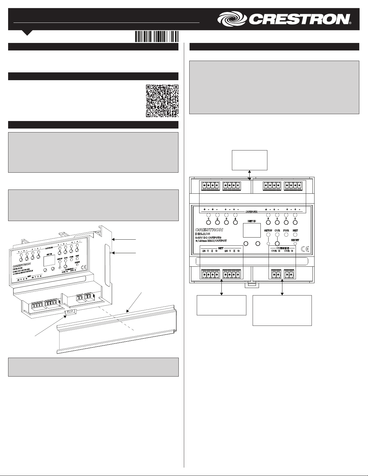
1. Place the top of the DIN-AO8’s rail mount over the top of the DIN rail.
2. Tilt the bottom of the DIN-AO8 toward the DIN rail until it snaps into place.
NOTE: When mounting DIN rail products, it may be necessary to use a at-head
screwdriver to pull the DIN rail release tab while snapping the device onto the DIN rail.
NOTE: Certain third-party DIN cabinets provide space for an informational label
between each DIN rail row. Crestron’s Engraver software (version 4.0 or later) can
generate appropriate labels for all Crestron DIN rail products.
Hardware Hookup
Make the necessary connections. Apply power after all connections have been made.
WARNING: Prior to connecting the device, turn off power at the circuit breaker. Failure
to do so may result in serious personal injury or damage to the device. Restore power
after all connections have been made.
CAUTION: Connecting this device to the wrong type of load or short-circuiting the load
can cause severe product damage. Each load should be tested to identify a short-circuit
condition prior to wiring the load to the module.
NOTE: Use copper wire only.
NOTE: Each switch leg of the DIN-AO8 may be fed from a separate circuit breaker.
When making OUTPUTS, NET, and OVERRIDE connections, strip the ends of the wires
approximately 7/16 in (11 mm). Use care to avoid nicking the conductors. Tighten the
connector to 5 in-lb (0.5 to 0.6 N-m). The wire gauge should be 14 to 26 AWG.
When making power connections to the DIN-AO8, use a Crestron power supply.
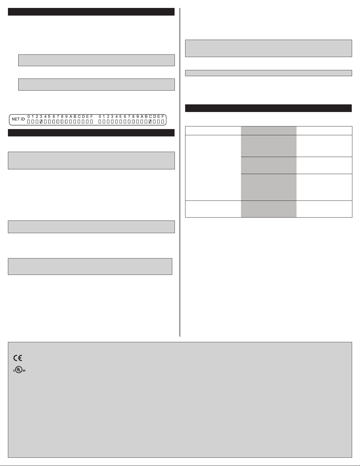
Hardware Connections for the DIN-AO8
OUTPUTS:
To Devices with
Analog Inputs
DIN-AO8
Top
DIN Rail (Not
Supplied)
DIN Rail
Release
NOTE: To remove the DIN-AO8 from the DIN rail, use a small, at object (i.e., a
at-head screwdriver) to pull the DIN rail release and tilt the bottom of the DIN-AO8
away from the DIN rail.
NET:
To Control System and
Other Cresnet Devices
OVERRIDE:
From Device Providing
Override Signal and to Other
Devices Receiving Override
Signal
Set the Net ID
The Net ID of the DIN-AO8 has been factory set to 88. The Net IDs of all devices in the
same system must be unique. The Net ID can be changed from the front panel of the
DIN-AO8 or from a personal computer via Crestron Toolbox™.
Set the Net ID using the front panel.
1. Press the SETUP button to enter Setup mode. The SETUP LED illuminates.
2. Press the left and right buttons under the NET ID display to change the Net ID.
NOTE: The DIN-AO8 will leave Setup mode after 10 seconds of inactivity and
revert to the previously set Net ID.
3. When the desired Net ID is displayed, press the SETUP button to exit the Setup
mode. The SETUP LED extinguishes.
NOTE: If an invalid Net ID is set (i.e., 00, 02, FF), “Er” will be displayed on the NET
ID display, and the DIN-AO8 will revert to the previously set Net ID.
A small Net ID label is provided on the DIN-AO8 to document the unit’s Net ID in the case
where power is not available. Apply a mark over the digits that correspond to the assigned
Net ID.
NET ID Label (“3C” Shown)
Operation
The DIN-AO8 can be controlled via its front panel as well as from a control system. The
following local controls are available.
NOTE: Before using the DIN-AO8, ensure the device is using the latest rmware. Check
for the latest rmware for the DIN-AO8 at www.crestron.com/rmware. Firmware is
loaded onto the device using Crestron Toolbox™.
Manual Load Control
The level of each of the analog outputs can be manually controlled from the front panel.
To toggle the output between off (0V) and the programmed upper limit (10V), tap an output
button. The corresponding LED illuminates, and the output level is shown on the NET ID
display (“oF” for off, “On” for on) for two seconds, after the button is released.
To ramp the voltage up or down (until it reaches a limit), press and hold the output button.
To change the ramp direction, release the output button, and then press and hold it again.
The corresponding LED illuminates, and the output level is shown on the NET ID display
as a percentage (01-99) for two seconds, after the button is released.
NOTE: The control system program may change the settings if Override mode is not
enabled.
Establish Override Mode Levels
Override mode disables the control system program and sets all of the output states to the
stored override values. The state of each output can be saved as an override setting,
which can be automatically recalled when the Override mode is enabled.
NOTE: The control system program has a setting that can prevent locally saving the
override state. If this setting is enabled, the display shows “Er” when trying to save
override states. For more information, refer to the SIMPL Windows help le.
To save the load level as an override setting, set all of the loads to either on or off, and
then press and hold the OVR button for three seconds. The OVR LED blinks to indicate
the new override setting has been stored.
Toggle Override Mode
The Override mode overrides the control system program and sets all of the output levels
to the saved override values. For instructions on saving override levels, refer to “Establish
Override Mode Levels.”
To enable the Override mode, press and release the OVR button. The OVR LED ashes
slowly.
NOTE: If the Override mode was enabled from an external device (i.e., a contact
closure is present on the OVERRIDE terminals), the OVR LED ashes quickly. Pressing
the OVR button has no effect.
To disable the Override mode, press the OVR button again. The OVR LED extinguishes
and the output levels return to the values set by the control system program.
NOTE: The factory default override level is 100% if override levels have not been saved.
Reset
To reboot the DIN-AO8, press the RESET button. The output levels will be set to the level
currently specied by the control system program. If the control system does not provide
a value, the outputs will be set to the previously set levels.
Troubleshooting
The following table provides corrective action for possible trouble situations. If further
assistance is required, please contact a Crestron customer service representative.
TROUBLE POSSIBLE CAUSE(S) CORRECTIVE ACTION
The DIN-AO8 does not
function.
There is a loss of
functionality due to an
electrostatic discharge.
The device is not
communicating with the
network.
The device is not receiving
power from a Crestron
power source.
The device is not receiving
sufcient power.
The device is not
grounded properly.
Use Crestron Toolbox to
poll the network. Verify the
network connection to the
device.
Use a Crestron power
source. Verify the
connections.
Use the Crestron Power
Calculator to help
calculate how much
power is needed for the
system.
Check that all of the
ground connections have
been made properly.
As of the date of manufacture, the DIN-AO8 has been tested and foudn to comply with specications
for CE marking.
This product is Listed to applicable UL Standards and requirements by Underwriters Laboratories Inc.
Federal Communications Commission (FCC) Compliance Statement
This device complies with part 15 of the FCC Rules. Operation is subject to the following two
conditions: (1) This device may not cause harmful interference, and (2) this device must accept any
interference received, including interference that may cause undesired operation.
This equipment has been tested and found to comply with the limits for a Class B digital device,
pursuant to part 15 of the FCC Rules. These limits are designed to provide reasonable protection
against harmful interference in a residential installation. This equipment generates, uses and can
radiate radio frequency energy and if not installed and used in accordance with the instructions, may
cause harmful interference to radio communications. However, there is no guarantee that interference
will not occur in a particular installation. If this equipment does cause harmful interference to radio or
television reception, which can be determined by turning the equipment off and on, the user is
encouraged to try to correct the interference by one or more of the following measures:
• Reorient or relocate the receiving antenna.
• Increase the separation between the equipment and receiver.
• Connect the equipment into an outlet on a circuit different from that to which the receiver is
connected.
• Consult the dealer or an experienced radio/TV technician for help.
The product warranty can be found at www.crestron.com/warranty.
The specic patents that cover Crestron products are listed at patents.crestron.com.
Certain Crestron products contain open source software. For specic information, please visit
www.crestron.com/opensource.
Crestron, the Crestron logo, Cresnet, and Crestron Toolbox are either trademarks or registered
trademarks of Crestron Electronics, Inc. in the United States and/or other countries. UL and the UL
logo are either trademarks or registered trademarks of Underwriters Laboratories, Inc. in the United
States and/or other countries. Other trademarks, registered trademarks, and trade names may be
used in this document to refer to either the entities claiming the marks and names or their products.
Crestron disclaims any proprietary interest in the marks and names of others. Crestron is not
responsible for errors in typography or photography.
This document was written by the Technical Publications department at Crestron.
©2015 Crestron Electronics, Inc.
Crestron Electronics, Inc. Installation & Operation Guide - DOC. 6663B
15 Volvo Drive Rockleigh, NJ 07647 (2020745)
Tel: 888.CRESTRON 08.15
Fax: 201.767.7576 Specications subject to
www.crestron.com change without notice.
 Loading...