

Page 1
CRESTRON CNWMBG-10A Wall-Mount Wired Panels
DESCRIPTION:
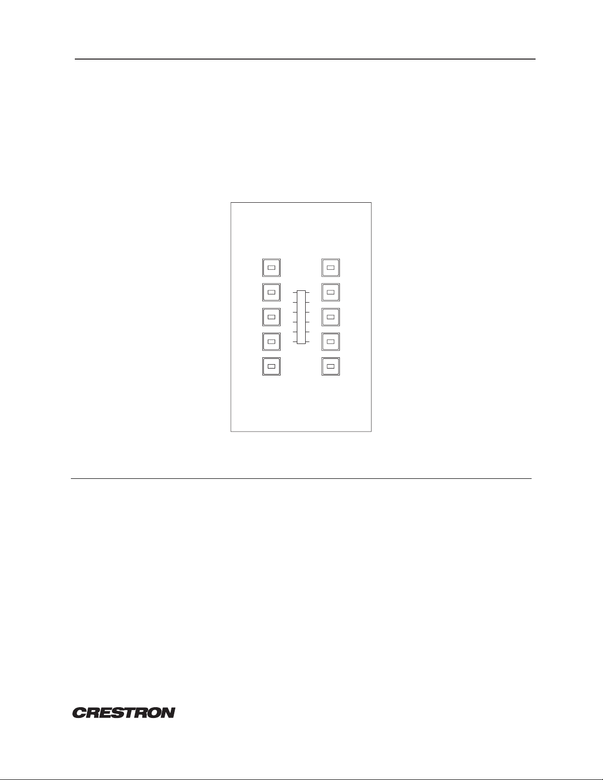
The CNWMBG-10A wired panel, illustrated in figure 1, interfaces with a CRESNET II control system over
the CRESNET II network. The panel uses 10 miniature pushbuttons with self-contained feedback LEDs and
includes a standard bargraph. The CNWMBG-10A is designed for wall-mounting using a standard singlegang electrical box. Custom panel finishes, engraving, colored button caps, and the omission of unused
buttons are all standard.
Figure 1. CNWMBG-10A, Wall-Mount Wired Panel
INSTALLATION/SETUP:
Identity Code
Each unique panel or component on the CRESNET II network requires the setting of an identity code (ID
CODE). ID CODES are two-digit hexadecimal numbers, from 10 to FE.
1
3
5
7
9
CRESTRON
2
4
6
8
10
The ID CODE of the panel should be set to match the ID CODE specified in the NET.ID statement of the
CRESNET II SIMPL-C program referencing the panel (refer to SYNTAX section). To set an ID CODE,
disconnect power. Accessible through the back cover are two miniature circuit-mounted rotary
switches, identified as H and L. These 16-position hexadecimal switches can be set to 0 through F. Using
a small screwdriver, rotate the arrow in the center of the switch marked H so that it points to the first
(or most-significant) digit or letter of the specified ID CODE. Set the switch marked L to the second
(least-significant) digit or letter of the specified ID CODE.
REMOTE CONTROL SYSTEMS
1 DOC. 8078
Specifications subject to change without notice.
Page 2
CRESTRON CNWMBG-10A Wall-Mount Wired Panels
Preparation for Use
The 4-pin connector marked NET must be wired to the CRESNET II network. Network termination points
are available at the control system power supply. Network units may also be daisy-chained together.
Refer to the latest revision of CNPWS power supplies (Docs. 8017 and 8091) in the CRESNET II manual
for wire gauge specifications and connection detail.
PROGRAMMING:
The panel drawing in figure 1 shows the location of the SIMPL-C button numbers and their corresponding
button positions. Buttons or bargraphs which are not used need not be assigned a signal name.
SYNTAX:
The following syntax codes are provided for compatibility purposes only.
NET.ID <10 to FE>: CNWP
i1,o1 = <signal name> \ button and LED combined
i2 = <signal name> \ independent button
o2 = <signal name> \ independent LED
" = " "
i10 = <signal name>
o10 = <signal name>
<BAR1> = <signal name> \ first bargraph level
FURTHER INQUIRIES:
If after reviewing this Operations Guide you still have additional questions, please contact a CRESTRON
technical support representative by dialing (800) 237-2041 or (201) 894-0660.
REMOTE CONTROL SYSTEMS
2 DOC. 8078
Specifications subject to change without notice.
 Loading...