

Page 1
Page 2

Page 3

CRESTRON CNRFHT-15/30 & CNIRHT-15/30 Hand-Held Wireless Transmitters
TABLE OF CONTENTS
PAGE
DESCRIPTION................................................................ 1
Functional Description........................................... 1
CNRFHT-15/30............................................ 1
CNIRHT-15/30............................................. 1
Sleep Mode ................................................ 1
Physical Description.............................................. 2
Configuration Differences..................................... 3
LEADING SPECIFICATIONS ........................................... 3
CONTROLS AND INDICATORS...................................... 3
Controls............................................................... 3
Indicators.............................................................. 3
INSTALLATION/SETUP.................................................. 4
Identity Code ........................................................ 4
RF Receiver/Transmitter Tuning............................. 6
RF Receiver................................................. 6
RF Transmitter............................................. 6
PROGRAMMING ........................................................... 7
TESTING/TROUBLESHOOTING..................................... 10
SYNTAX ........................................................................ 11
APPENDIX..................................................................... 11
REMOTE CONTROL SYSTEMS
DOC. 8054C
Page 4

Page 5
CRESTRON CNRFHT-15/30 & CNIRHT-15/30 Hand-Held Wireless Transmitters
POWER
CHANNEL
CRESTRON
CNRFHT
VOLUME
MUTE
Tuning
Capacitor
Transmit
LED
6.5 in
16.5 cm
2.7 in
6.9 cm
POWER
CHANNEL
CRESTRON
CNIRHT
VOLUME
MUTE
0.8 in
2.1 cm
DESCRIPTION:
Functional Description
CNRFHT-15/30:
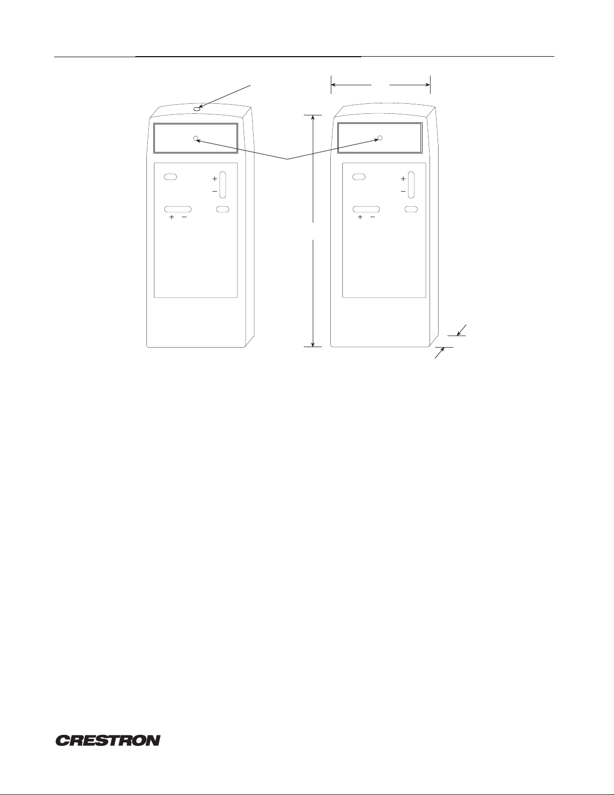
The CNRFHT, illustrated in figure 1, is a hand-held radio-frequency (RF) transmitter. The unit is designed to operate
with the CRESNET II remote control system (herein referred to as the CRESNET II system) via a RF wireless
receiver, CNRFGW Wireless Gateway. The CNRFHT is available with 15 or 30 button controls. Depression of any
button on the CNRFHT customized 15- or 30-button panel initiates a RF signal transmission to the CNRFGW.
CNIRHT-15/30:
The CNIRHT, illustrated in figure 1, is a hand-held infrared (IR) transmitter. The unit is designed to operate with the
CRESNET II system via an IR wireless receiver, CNIRGW Wireless Gateway. The CNIRHT is available with 15 or
30 button controls. Depression of any button on the CNIRHT customized 15- or 30-button panel initiates an IR
signal transmission to the CNIRGW.
Sleep Mode:
CNRFHT and CNIRHT have a power-saving mode, known as sleep mode, to extend battery life. If the unit remains
inactive (no buttons are depressed) for approximately six hours, the unit enters a default setting, sleep mode.
Actual inactivity duration to initiate sleep mode may vary. To reactivate the unit from sleep mode, depress and hold
Figure 1. CRESTRON Hand-held Wireless Transmitters
REMOTE CONTROL SYSTEMS
1 DOC. 8054C
Page 6

CRESTRON CNRFHT-15/30 & CNIRHT-15/30 Hand-Held Wireless Transmitters
a button on the unit until it begins transmitting. Transmission is indicated by the illumination of a red LED located
above the button panel cover.
Physical Description
NOTE
CRESTRON does not recommend designing large button caps for single functions. Depressing
the center of a large button cap can cause the unit to transmit incorrectly which may result in
the control system misinterpreting the user's intent. Therefore, design large button caps for
dual functions, such as a volume up/volume down rocker-type button.
CNRFHT and CNIRHT electronic hardware is housed in a slim, high-impact molded ABS black plastic enclosure
(refer to figure 2). A 30-button array on the printed circuit board is covered by a customized button panel. All
button panels include custom engraving, colored button caps, choice of button configurations, and panel finishes.
Small and large button caps are available. A small button cap covers one button. A large button cap covers two
buttons. Refer to the latest version of the CRESNET II Engraving Worksheet for CNRFHT and CNIRHT (Doc. 5344)
to design a unique button panel. Omission of unused buttons is standard. A red LED is located above the button
panel cover.
CRESTRON
Front View
(Customized button panel removed
to reveal 30 button array.)
Aside from the diversity in button panel configuration, the only external difference between CNRFHT and CNIRHT is
the type of plastic material at the pointing end of each unit. CNRFHT has a black plastic cover with a tuning hole
(refer to figure 1) and CNIRHT has a ruby-colored IR signal filter.
REMOTE CONTROL SYSTEMS
Rear View
Figure 2. Physical Views of CNRFHT and CNIRHT
2 DOC. 8054C
Battery Cover
Page 7

CRESTRON CNRFHT-15/30 & CNIRHT-15/30 Hand-Held Wireless Transmitters
A nine-volt battery is included with all units. Access to the battery is permitted after the battery cover, located on
the underside of the unit, is removed.
Configuration Differences
The CNRFHT and CNIRHT each have two different configurations which are depicted in table 1.
Table 1. CNRFHT and CNIRHT Configurations
CONFIGURATION DESCRIPTION
CNRFHT-15 & CNIRHT-15 15 buttons on a customized panel
CNRFHT-30 & CNIRHT-30 30 buttons on a customized panel
LEADING SPECIFICATIONS:
Table 2 provides a summary of leading specifications for the CNRFHT and CNIRHT. Dimensions and weight are
approximations rounded to the nearest tenth unit.
Table 2. Leading Specifications
SPECIFICATION DETAILS
Battery 9V DC
Dimensions & Weight Height: 6.5 in (16.5 cm)
CONTROLS AND INDICATORS:
Controls
Button controls are custom designed. CNRFHT and CNIRHT are available with 15 to 30 functional buttons.
Function definition is determined by application of the unit within the CRESNET II system. The customized button
controls correspond to signal names that are defined in the SIMPL program.
A tuning hole is located on the pointing end of the CNRFHT. This control mechanism permits the user to adjust the
frequency. Refer to Installation/Setup for tuning techniques.
Indicators
There is only one indicator located on the CNRFHT and CNIRHT. The indicator is a red LED and resides on the face of
the unit above the button panel cover. The LED indicates IR/RF transmission and illuminates when a button is
depressed.
Width: 2.7 in (6.9 cm)
Depth: 0.8 in (2.1 cm)
Weight: 0.3 lb (0.2 kg)
REMOTE CONTROL SYSTEMS
3 DOC. 8054C
Page 8

CRESTRON CNRFHT-15/30 & CNIRHT-15/30 Hand-Held Wireless Transmitters
INSTALLATION/SETUP:
Identity Code
Every hand-held wireless transmitter communicating with either the CNRFGW or CNIRGW requires a unique
identity code (ID CODE). For RF devices the ID CODE is referred to as RF ID. For IR devices the ID CODE is referred
to as IR ID. There are 256 possible two-digit hexadecimal alphanumeric codes ranging from 00 to FF. To maintain
code diversity within the CRESNET II system, use codes between 10 and FE for the transmitters.
NOTES
1. The ID CODE on the CNRFHT and CNIRHT is factory set to 20.
2. Do not use 00 or FF as an RF/IR ID.
3. Do not confuse RF/IR ID with network (NET) ID.
To set an ID CODE complete the following steps.
1. Position the unit button-side down so the battery compartment is accessible.
2. Remove the battery cover.
3. Remove four screws from the unit (two screws are located within the battery compartment).
4. Gently lift the rear cover off the unit.
5. Refer to figure 3 and locate an eight-position SIP switch on the printed circuit board. Switches labeled 1
Rear Cover and
Battery Cover
Removed.
through 4 represent the least-significant digit or letter of the ID CODE. Switches labeled 5 through 8
represent the most-significant digit or letter of the ID CODE.
SV8
2F
SV8
2F
8
7
6
5
4
32
1
8
7
6
5
4
32
1
REMOTE CONTROL SYSTEMS
Enlarged
8- Position
SIP Switch
(set to 20)
Figure 3. SIP Switch Location
4 DOC. 8054C
Page 9

CRESTRON CNRFHT-15/30 & CNIRHT-15/30 Hand-Held Wireless Transmitters
6. Refer to table 3 and translate the ID CODE two-digit hexadecimal number or letter into an eight-digit SIP
switch code.
NOTES
1. The ID CODE of the unit is factory set to 20. This hexadecimal setting corresponds to an
eight-digit SIP switch code of 00000100, with respect to SIP switches 1 through 8.
2. A "1" in the table indicates that the switch should be set in the direction of the arrow
head located on the SIP switch. A "0" in the table above indicates that the switch should be
set in the opposite direction of the arrow head.
Table 3. CNRFHT and CNIRHT SIP Switch Settings
Hexadecimal
NUMBER OR
LETTER
0 00000000
1 00010001
2 00100010
3 00110011
4 01000100
5 01010101
6 01100110
7 01110111
8 10001000
9 10011001
A 10101010
B 10111011
C 11001100
D 11011101
E 11101110
F 11111111
Most-Significant
SIP Switch Digit
8765
Least-Significant
SIP Switch Digit
4321
7. Use a small screwdriver or a small pair of pliers and adjust the switch, appropriately.
8. Ensure all screw standoffs are properly situated and place the rear cover onto the unit.
9. Secure the rear cover by tightening the four screws.
10. Secure the battery cover over the battery compartment.
REMOTE CONTROL SYSTEMS
5 DOC. 8054C
Page 10

CRESTRON CNRFHT-15/30 & CNIRHT-15/30 Hand-Held Wireless Transmitters
RF Receiver/Transmitter Tuning
NOTE
The following installation instructions are for the CNRFHT only.
The CNRFHT and CNRFGW are factory tuned and normally do not require tuning. However, in some cases it may be
necessary to tune the CNRFHT transmitter for the CNRFGW to receive signals properly. Complete the following
steps to tune the transmitter and receiver.
RF Receiver
1. Verify CNRFGW power is on. The green LED marked NET PWR on the receiver illuminates when power is on.
2. Position the CNRFGW on its side so that the silk-screened face is visible.
3. To optimize reception extend the CNRFGW antenna vertically to a height of nine to 10 inches.
CAUTION
Do not force the tuning adjustment on the receiver. Over exerting the tuning adjustment may
damage the unit.
4. Use a nylon (non-conductive) tuning tool and gently turn the tuning adjustment on the face of the CNRFGW
clockwise, until it comes to a stop.
5. Hold the tuning tool firmly; gently turn the tuning adjustment counterclockwise, two complete turns. This sets
the receiver frequency to 300 MHz, which is the factory standard setting. Frequencies ranging between 270
and 330 MHz can be used by turning the tuning adjustment to different positions.
RF Transmitter
CAUTION
Do not force the tuning adjustment on the transmitter. Over exerting the tuning adjustment
may damage the unit.
1. Place the tuning tool into the tuning hole located at the pointing end of the CNRFHT; gently turn the tuning
adjustment clockwise until it comes to a stop.
2. With CNRFHT in hand, stand approximately six feet from the CNRFGW.
3. Insert the tuning tool into the CNRFHT; gently turn the tuning adjustment counterclockwise, approximately
two full turns.
4. Aim the CNRFHT at the CNRFGW antenna; depress any button on the transmitter.
5. While aiming and depressing any button, gently turn the tuning tool in either direction, until the red LED marked
SIGNAL on the CNRFGW illuminates.
REMOTE CONTROL SYSTEMS
6 DOC. 8054C
Page 11

CRESTRON CNRFHT-15/30 & CNIRHT-15/30 Hand-Held Wireless Transmitters
6. Once the frequency is located, it may be necessary to fine tune the device by slowly turning the tuning tool in
either direction, until the red LED marked SIGNAL is brightly illuminating. The LED must be at its brightest
setting to confirm the unit is tuned to the highest lobe of the frequency range.
7. Move to a different location within the room; depress any button on the transmitter to verify proper frequency
setting.
NOTE
The red LED on the CNRFGW will not illuminate when it is approximately 10 to 15 feet from the
CNRFHT. The system is still functioning, but the threshold to illuminate the signal is too low.
However, the red LED on the CNRFHT illuminates when a button is depressed, indicating the
remote is transmitting.
8. If "dead" spots are found within the room, insert the tuning tool into the CNRFHT and carefully make further
adjustments in either direction to fine tune the system.
PROGRAMMING:
A 30-button array is located beneath the custom button panel of each CNRFHT and CNIRHT. Refer to figure 4 for an
illustrative layout of transmitter button numbers beneath a sample button panel. The numbering for each button is
constant. For each button input, a signal name must be defined in the SIMPL program. Unused buttons need not be
assigned signal names. An example following figure 4 illustrates button definition in the CRESNET II Workshop.
Access the following tables from the "Define Network" section of the SIMPL-I Menu. An example of SIMPL-C
programming for the same custom button panel design is shown in the Appendix.
REMOTE CONTROL SYSTEMS
VOLUME
MUTE
5678
13 14 15 16
21 22 23 24
272625
3029
CRESTRON
4321
1211109
20191817
28
POWER
CHANNEL
Customized button panel removed.
Each button is illustrated with its corresponding number.
Figure 4. Button Number Layout
7 DOC. 8054C
Page 12

CRESTRON CNRFHT-15/30 & CNIRHT-15/30 Hand-Held Wireless Transmitters
System PF: 4.5 Net PF: 3.0
Net ID Net Device Description P.F.
03: CNRFGW CNRFGW/CNIRGW Receiver 3.0
04:
05:
06:
07:
08:
09:
0A:
0B:
0C:
TAB to select entries PgUp/PgDn to find ID
F2-Detail F3-Display Signals
ESC to Def Equip Define Network F1=Help
Net ID: 03
CNRFGW
CNRFGW/CNIRGW Receiver
RF ID Transmitter Description
12 CNRFHT 16/32/56 - button hand-held panel
14 CNIRHT 16/32/56 - button hand-held panel
F2-Detail TAB - Select Transmitter to Enter ID
ESC to Define Rack Module Detail F1=Help
REMOTE CONTROL SYSTEMS
8 DOC. 8054C
Page 13

CRESTRON CNRFHT-15/30 & CNIRHT-15/30 Hand-Held Wireless Transmitters
CNRFGW Net ID: 03
RF ID 12 CNRFHT
CNRFHT-15/30 DEFINITION
BUTTON SIGNAL NAMES
1: POWER
2:
3:
4: VOL_UP
5:
6:
7:
8: VOL_DOWN
CHANNEL_UP
9:
10:
11:
12: MUTE
CHANNEL_DOWN
F2-Detail F3-Display Signals F4 -Auto-Increment
ESC to Define Net Panel Detail F1=Help
CNRFGW Net ID: 03
RF ID 14 CNIRHT
CNIRHT-15/30 DEFINITION
BUTTON SIGNAL NAMES
1: POWER
2:
3:
4: VOL_UP
5:
6:
7:
8: VOL_DOWN
CHANNEL_UP
9:
10:
11:
12: MUTE
CHANNEL_DOWN
F2-Detail F3-Display Signals F4 -Auto-Increment
ESC to Define Net Panel Detail F1=Help
REMOTE CONTROL SYSTEMS
9 DOC. 8054C
Page 14

CRESTRON CNRFHT-15/30 & CNIRHT-15/30 Hand-Held Wireless Transmitters
TEST/TROUBLESHOOTING:
Table 4 provides corrective action for possible trouble situations. If further assistance is required, please contact a
CRESTRON technical support representative.
Table 4. Troubleshooting Guide
TROUBLE POSSIBLE CAUSE(S) CORRECTIVE ACTION
LED on unit does not
illuminate.
Intermittent response during
transmission.
No response from CRESNET II
system.
No battery in unit or battery is dead. Install new battery.
Unit is in sleep mode. Depress and hold any button until unit
transmits.
Refer to causes when LED does not illuminate. Refer to corrective action when LED does not
illuminate.
CNRFHT is not tuned to CNRFGW. Refer to Installation/Setup for tuning
instructions.
Receiver antenna not extended to optimum length. Extend receiver antenna to nine or 10 inches.
Receiver is blocked or moved. For IR unit, verify direct line-of-sight. For RF
unit, verify that heavy metal is not in vicinity
of transmission.
CNRFGW is in contact with metal. Verify that heavy metal is not in vicinity of
transmission.
Refer to causes when LED does not illuminate and
intermittent response during transmission occurs.
NET ID of receiver is incorrectly set. Enter Performance Viewport in the CRESNET
RF ID or IR ID is incorrectly set. Verify that the RF ID or IR ID for the
Program does not match hardware. Verify correct program is loaded in system via
Receiver is unplugged (no power). Verify power to the receiver.
Two or more receivers are too close together. Verify that multiple receivers are properly
Wrong transmitter in use. If multiple transmitters are accessible, verify
Refer to corrective action when LED does not
illuminate and intermittent response during
transmission occurs.
Workshop. Depress the F4 key to poll the
network. Verify that the NET ID for the
receiver is properly set to match the SIMPL
program.
NOTE:
After changing the CNRFGW identity code,
disconnect and reconnect the network
connector.
transmitter is properly set to match the
SIMPL program.
Performance Viewport Workshop.
spaced (
proper unit is used.
>50 feet) from each other.
REMOTE CONTROL SYSTEMS
10 DOC. 8054C
Page 15

CRESTRON CNRFHT-15/30 & CNIRHT-15/30 Hand-Held Wireless Transmitters
SYNTAX:
The following syntax codes are provided for compatibility purposes only.
NOTE
The CNRFHT and CNIRHT units are defined as CNRFT in SIMPL-C.
NET.ID < 03 to FE > : CNRFGW \ Codes received by a CNRFGW
TRANSMITTER < RF IDCODE > : CNRFT
i1 = <signal name> \ Independent button.
i2 = <signal name>
i3 = <signal name>
" " " "
APPENDIX:
The following is a sample of SIMPL-C programming for the CNRFHT and CNIRHT illustrated in figures 1 and 4.
NET.ID 10: CNRFGW \ CNRFGW is at NET ID CODE 10.
TRANSMITTER 20: CNRFT \ CNRFHT-30 is at ID CODE 20.
i1 = POWER \ Small button
i4 = VOL_UP \ Rocker with two functions is treated
i8 = VOL_DOWN \ as two pushbuttons.
i9 = CHANNEL_UP \ Long horizontal keys are treated like
i10 = CHANNEL_DOWN \ large vertical keys.
i12 = MUTE \ Small button.
REMOTE CONTROL SYSTEMS
11 DOC. 8054C
Page 16

 Loading...