

Crestron CNCS User Manual
CRESTRON CNCS AC Current Sensor
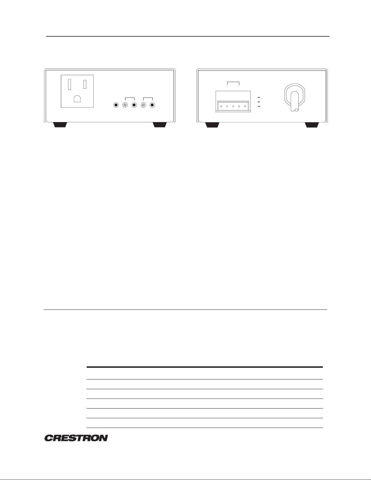
FRONT PANEL BACK PANEL
AC
OUTPUT
MAX
1000 W
DESCRIPTION:
The CNCS, illustrated in figure 1, measures the average current of each half cycle of an AC load.
The current sensing circuitry is highly sensitive with a wide range of adjustment. The high
sensitivity makes the CNCS ideally suited for use with low power units such as VCRs, TV tuners,
and satellite receivers. The wide range makes the CNCS ideally suited for medium and high
powered units such as TV sets, video projectors, and power amplifiers.
The CNCS provides an isolated relay closure when the average current drawn by a monitored unit
exceeds the FULL LOAD preset threshold.
A second set of relay contacts determine whether the average current is less than FULL LOAD,
but more than no load. This PARTIAL LOAD threshold is also adjustable. The FULL LOAD and
PARTIAL LOAD relay closures are mutually exclusive so that only one closure is ever connected to
the common. However, FULL LOAD and PARTIAL LOAD indicators are implemented, so that at
FULL LOAD, both LEDs are illuminated.
CNCS
PARTIAL
FULL
LOAD
THRESHOLD
CRESTRON ELECTRONICS, INC.
CW
PWR
=
INCREASED
LOAD
Figure 1. CNCS, AC Current Sensor
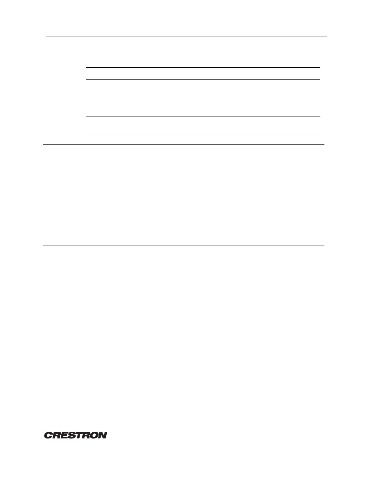
24+
OUT
F
AC INPUT
P
C
GND
COMMON
C
PARTIAL
P
FULL
F
1000 W
MAX
Threshold adjustments are accomplished by use of a 15-turn precision potentiometer (POT). The
POT permits highly accurate and repeatable current threshold settings.
LEADING SPECIFICATIONS:
Table 1 provides a summary of leading specifications for the CNCS. Dimensions and weight are
approximations rounded to the nearest tenth unit.
SPECIFICATION DETAILS
Power Requirements 24 VDC, Load Factor of 3 W
Maximum AC Load 8.5 A, 1 KW at 120 VAC
Minimum AC Load 0.033 A, 4 W at 120 VAC
Voltage Range 0 to 220 VAC, 45 to 65 Hz
Relay Contact Rating 1 A, 24 V (AC or DC)
REMOTE CONTROL SYSTEMS
Specifications subject to change without notice.
Table 1. Leading Specifications
1 DOC. 8079C
CRESTRON CNCS AC Current Sensor
Table 1. Leading Specifications (continued)
SPECIFICATION DETAILS
Dimensions & Weight Height: 1.8 in (4.6 cm)
Width: 4.2 in (10.7 cm)
Depth: 4.3 in (10.9 cm)
Weight: 1.8 lb (0.8 kg)
Construction 18 gauge cold-rolled steel,
black painted finish
LED INDICATORS:
PWR (Power)
The green LED illuminates when 24 volts DC is supplied to the CNCS.
FULL LOAD
The red LED illuminates when FULL LOAD threshold has been exceeded.
PARTIAL LOAD
The yellow LED illuminates when PARTIAL LOAD threshold has been exceeded.
USER ADJUSTMENTS:
FULL LOAD Threshold
Clockwise (CW) rotation of the 15-turn POT increases threshold (i.e., reduces sensitivity) and changes
partial load threshold, accordingly.
PARTIAL LOAD Threshold
Clockwise rotation of the 15-turn POT increases threshold (i.e., reduces sensitivity).
THRESHOLD ADJUSTMENTS:
Refer to figure 2 for a block diagram illustrating hookup connections for the CNCS.
NOTES
1. Do not attempt adjustments during periods of high or low power line voltage or
voltage fluctuations.
2. Partial power output may be used as the primary output if increased sensitivity is
required.
3. If the partial power output is not required, the partial power adjustment may be
placed in any position which does not cause LED flashing or relay chatter.
REMOTE CONTROL SYSTEMS
2 DOC. 8079C
Specifications subject to change without notice.
 Loading...