

Page 1

Crestron CLW-SW1/4RF,
CLW-SWS1/4RF, CLW-SLVS1RF
infiNET™ Switches
Operations Guide
Page 2

This document was prepared and written by the Technical Documentation department at:
Crestron Electronics, Inc.
15 Volvo Drive
Rockleigh, NJ 07647
1-888-CRESTRON
Windows
®
and Windows® XP are registered trademarks of Microsoft Corporation in the United States and other countries.
All brand names, product names and trademarks are the property of their respective owners.
©2005 Crestron Electronics, Inc
Page 3

Crestron CLW-SW1/4RF, -SWS1/4RF, -SLVS1RF infiNET™ Switches
Contents
infiNET™ Switches: CLW-SW1/4RF, -SWS1/4RF, -SLVS1RF 1
Introduction ...............................................................................................................................1
Features and Functions................................................................................................ 1
Specifications ..............................................................................................................2
Physical Description.................................................................................................... 4
Industry Compliance ...................................................................................................7
Acquiring the Switch on the infiNET Network .........................................................................8
Acquiring the Switch................................................................................................... 8
Removing Gateway Information from a Switch..........................................................9
Operation ...................................................................................................................................9
Mode Selection Switch................................................................................................ 9
-SLVS1RF................................................................................................................. 11
Restoring Default Settings......................................................................................... 11
LED Behavior............................................................................................................11
Identity Code ...........................................................................................................................12
Using Touch Settable ID (TSID) to Set MNET ID ...................................................12
Manually Setting the MNET ID in Crestron Toolbox............................................... 19
Programming Software............................................................................................................21
Earliest Version Software Requirements for the PC .................................................22
Programming with D3 Pro & SystemBuilder............................................................ 22
Programming with SIMPL Windows........................................................................ 23
Uploading and Upgrading........................................................................................................ 28
Establishing Communications................................................................................... 28
Troubleshooting Communications ............................................................................31
Uploading a SIMPL Windows Program.................................................................... 31
Firmware Upgrade..................................................................................................... 34
Problem Solving ......................................................................................................................36
Troubleshooting......................................................................................................... 36
Bootloader .................................................................................................................37
Further Inquiries........................................................................................................ 38
Future Updates ..........................................................................................................38
Return and Warranty Policies.................................................................................................. 39
Merchandise Returns / Repair Service ......................................................................39
CRESTRON Limited Warranty.................................................................................39
Operations Guide - DOC. 6397 Contents • i
Page 4

Page 5

Crestron CLW-SW1/4RF, -SWS1/4RF, -SLVS1RF infiNET™ Switches
infiNET™ Switches:
CLW-SW1/4RF, -SWS1/4RF,
-SLVS1RF
Introduction
Features and Functions
The CLW-SW1RF (-SW1RF) one-button switch and CLW-SW4RF (-SW4RF)
four-button switch are stand-alone wall box switches that can also act as wireless
infiNET™ devices that report to a Crestron® control processor via a Crestron
infiNET wireless gateway.
infiNET Switches Functional Summary
• Two-way infiNET switches
⇒
2.4 GHz infiNET mesh network technology
⇒
Range up to 150 feet indoors, or 250 ft outdoors (subject to sitespecific conditions)
⇒
Range may be increased with the use of additional infiNET devices
or C2N-MNETRPT repeaters
⇒
“Wi-Fi” friendly operating frequency to avoid interference
• One-button and four-button configurations available in white, black,
and almond
• Can be ordered with custom-engraved buttons
• Can operate as a local load control or infiNET keypad.
These switches can be operated with a user-adjustable delay up to 10 minutes and 55
seconds. For more information, refer to “Operation” on page 9 for more information.
These infiNET switches are a part of Crestron’s line of lighting products using
infiNET mesh network technology. infiNET technology is “Wi-Fi” friendly and
provides fault tolerance and increased effective signal strength as network devices
are added.
As an infiNET device, these switches communicate with a Crestron control system
via a C2N-MNETGW infiNET Gateway. Up to 30 infiNET devices (including
C2N-MNETRPT infiNET Repeaters) can communicate with one C2N-MNETGW
Operations Guide - DOC. 6397 infiNET Switches: Crestron CLW-SW1/4RF, -SWS1/4RF, -SLVS1RF • 1
Page 6

infiNET™ Switches Crestron CLW-SW1/4RF, -SWS1/4RF, -SLVS1RF
infiNET Gateway and, if more devices are needed, more C2N-MNETGW gateways
may be added to a Cresnet® network.
Crestron infiNET switches operate on the 2.4 GHz “ISM band” (2400 MHz to
2483.6 MHz) at 10 mW. The output power of these devices allow RF signals to
travel approximately 150 feet indoors and 250 feet outdoors (subject to site-specific
conditions) without the use of repeaters or other infiNET devices. The range is
dependent on construction of the building, obstructions, and RF interference from
other devices. The location of the dimmer is an important factor in determining RF
performance. Adding more infiNET devices or repeaters to the network effectively
increases the range, strength, and reliability of the network.
The -SW1RF and -SW4RF feature a three-position mode selection switch. Refer to
“Operation” on page 9 for more information. In the absence of control system
communications, the switch can still be used to control the attached load.
The CLW-SWS1RF (-SWS1RF) and CLW-SWS4RF (-SWS4RF) are similar to the
-SW1RF and -SW4RF (respectively) with the added capability of working with one
or more slave units (CLW-SLVS1RF) in a multi-switch / single circuit application.
For more information, refer to the latest version of the infiNET Switches Installation
Guide (Doc. 6293) which is available from the Crestron website
(www.crestron.com/manuals).
The CLW-SLVS1RF (-SLVS1RF) is a slave unit that when used in conjunction with
the -SWS1RF or -SWS4RF acts as an additional switch control point in a multiswitch / single circuit application. It does not connect to an infiNET system and
cannot be used without a -SWS1RF or -SWS4RF. The -SLVS1RF does not have a
mode selection switch. It can only be programmed when used in conjunction with a
-SWS4RF (refer to “Attaching and Detaching the Electrical Load” on page 27).
Otherwise, it will emulate the RUN mode of the -SWS1RF (even if connected to a
-SWS4RF) unless the mode selection switch of the master is set to “OFF”.
These switches can be ordered with custom engraved buttons already installed by
Crestron. Engraved buttons cannot be installed or changed in the field. Contact
Crestron for more information.
These switches are available in white, almond, and black. White units are designated
by part numbers ending in “W”. Almond units are designated by part numbers
ending in “A”. Black units are designated by part numbers ending in “B”. Each
dimmer can be covered with a decorative faceplate (not supplied).
For installation instructions, refer to the latest version of the infiNET Switches
Installation Guide (Doc. 6293), which is available from the Crestron website.
Specifications
Following are specifications for the -SW1RF, -SW4RF, -SWS1RF, -SWS4RF, and
-SLVS1RF.
CLW-SW1/4RF, CLW-SWS1/4RF, & CLW-SLVS1RF Specifications
SPECIFICATION DETAILS
Power Requirements Line Power, 120 VAC, 60 Hz
Operating Frequency 2400 MHz to 2483.6 MHz
(802.15.4 compliant)
RF Output Power 10 mW
(continued on following page)
2 • infiNET Switches: Crestron CLW-SW1/4RF, -SWS1/4RF, -SLVS1RF Operations Guide - DOC. 6397
Page 7

Crestron CLW-SW1/4RF, -SWS1/4RF, -SLVS1RF infiNET™ Switches
CLW-SW1/4RF, CLW-SWS1/4RF, & CLW-SLVS1RF Specifications (continued)
SPECIFICATION DETAILS
Operating Ranges¹
Typical Distance
Indoors (without repeater)
Typical Distance Outdoors
150 ft
250 ft, subject to site-specific conditions
Default MNET ID -SW1RF/-SW4RF: 01/01
-SWS1RF/-SWS4RF: 01/01
Switch Type Single-Pole, Single-Throw
Load Type Incandescent, Tungsten-Halogen,
Fluorescent / High Intensity Discharge (HID),
Electronic Low Voltage, Magnetic Low
Voltage, Neon / Cold Cathode, Ceiling Fan
2-Series Control System Update
2,3
File
Version 3.154 or later
Load Ratings4
Incandescent / TungstenHalogen
-SW1RF/-SW4RF: 1000W
-SWS1RF/-SWS4RF: 1000W
-SLVS1RF: N/A
Magnetic Low Voltage5 -SW1RF/-SW4RF: 1000VA/750W
-SWS1RF/-SWS4RF: 1000VA/750W
-SLVS1RF: N/A
Neon / Cold Cathode5 -SW1RF/-SW4RF: 1000VA/750W
-SWS1RF/-SWS4RF: 1000VA/750W
-SLVS1RF: N/A
Electronic Low Voltage -SW1RF/-SW4RF: 1000W
-SWS1RF/-SWS4RF: 1000W
-SLVS1RF: N/A
Ceiling Fan -SW1RF/-SW4RF: 3A
-SWS1RF/-SWS4RF: 3A
-SLVS1RF: N/A
Minimum Load 40W / 0.5A
Operating Temperature and
Humidity
32°F to 104°F (0°C to 40°C)
10 to 90% Relative Humidity
(Non-Condensing)
Dimensions and Weight
-SW1RF/-SW4RF and
-SWS1RF/-SWS4RF:
Height: 4.13 in (10.48 cm)
Width: 2.38 in (6.03 cm)
Depth: 1.88 in (4.77 cm)
Weight: 4.9 oz (0.67 kg)
-SLVS1RF:
Height: 4.13 in (10.48 cm)
Width: 1.75 in (4.45 cm)
Depth: 1.88 in (4.77 cm)
Weight: 3.6 oz (0.50 kg)
1. The range is dependent on its placement and the building in which it is used. The construction of the
building, obstructions, and RF interference from other devices are factors determining the effective
range of the unit.
2. The latest software versions can be obtained from the Crestron website. Refer to the NOTE
following these footnotes.
3. Crestron 2-Series control systems include the AV2 and PRO2. Consult the latest Crestron Product
Catalog for a complete list of 2-Series control systems.
4. Refer to Derating Charts for Multigang Installations in the latest version of the infiNET Switches
Installation Guide (Doc. 6293) which is available from the Crestron website.
Operations Guide - DOC. 6397 infiNET Switches: Crestron CLW-SW1/4RF, -SWS1/4RF, -SLVS1RF • 3
Page 8
infiNET™ Switches Crestron CLW-SW1/4RF, -SWS1/4RF, -SLVS1RF
5. VA ratings are for input power to the transformer. If you do not know the input power requirement
of the transformer, use the bulb’s wattage rating to determine proper rating.
NOTE: Crestron software and any files on the website are for Authorized Crestron
dealers and Crestron Authorized Independent Programmers (CAIP) only. New users
may be required to register to obtain access to certain areas of the site (including the
FTP site).
Physical Description
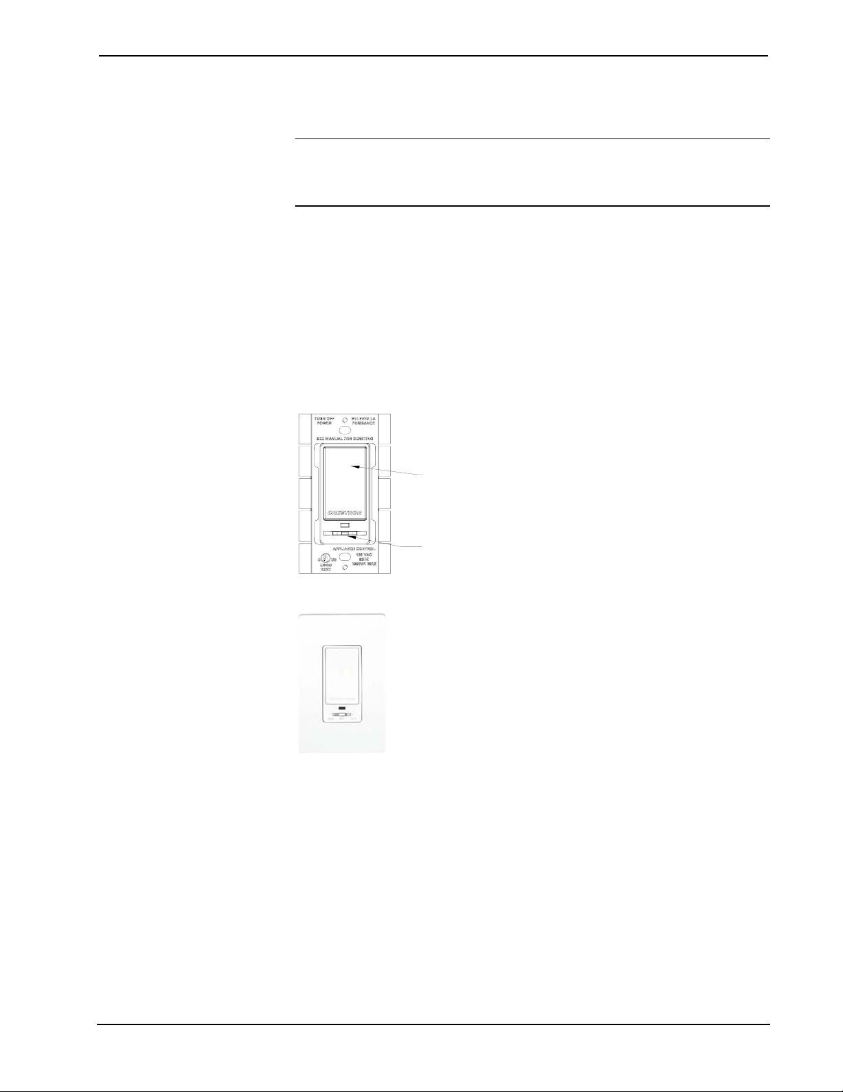
The -SW1RF and -SWS1RF have a light emitting diode (LED) with adjustable
brightness (via Crestron programming software), a rocker button, and a threeposition mode selection switch as shown in the following diagrams. The button may
be pushed at the top or bottom to perform certain functions. Pushing the button in the
middle does not do anything. The function of the pushbutton is determined by the
position of the mode selection switch. For more information, refer to “Operation” on
page 9.
Parts of CLW-SW1RF and -SWS1RF
Button
RUN SET O FF
CLW-SW1RF/-SWS1RF Shown in White
Mode Selection Switch
4 • infiNET Switches: Crestron CLW-SW1/4RF, -SWS1/4RF, -SLVS1RF Operations Guide - DOC. 6397
Page 9
Crestron CLW-SW1/4RF, -SWS1/4RF, -SLVS1RF infiNET™ Switches
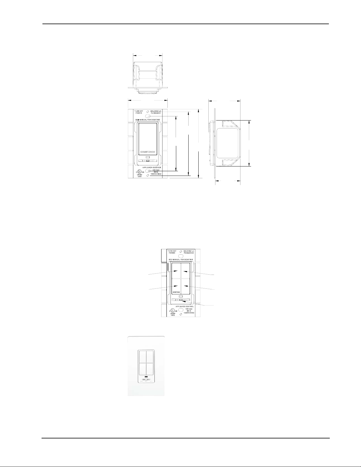
Physical View of CLW-SW1RF/-SWS1RF (Clockwise from Top; Top, Side, and Front)
1.75 in
(4.45 cm)
2.38 in
(6.03 cm)
3.81 in
(9.68 cm)
3.28 in
(8.32 cm)
OFFSETRUN
4.13 in
(10.48 cm)
1.88 in
(4.77 cm)
1.50 in
(3.81 cm)
2.70 in
(6.86 cm)
The -SW4RF and -SWS4RF have a light emitting diode (LED) with adjustable
brightness (via Crestron programming software), four pushbuttons, and a threeposition mode selection switch as shown in the following diagrams. Each of the
buttons may be pushed to perform certain functions. The function of each pushbutton
is determined by the position of the mode selection switch. For more information,
refer to “Operation” on page 9.
Parts of CLW-SW4RF, -SWS4RF
Button 1
Button 2
Button 4Button 3
RUN
SET OFF
Mode Selection Switch
CLW-SW4RF/-SWS4RF Shown in White
Operations Guide - DOC. 6397 infiNET Switches: Crestron CLW-SW1/4RF, -SWS1/4RF, -SLVS1RF • 5
Page 10
infiNET™ Switches Crestron CLW-SW1/4RF, -SWS1/4RF, -SLVS1RF
Physical View of CLW-SW4RF/-SWS4RF (Clockwise from Top; Top, Side, and Front)
1.75 in
(4.45 cm)
2.38 in
(6.03 cm)
RUN SET OFF
3.28 in
(8.32 cm)
3.81 in
(9.68 cm)
(10.48 cm)
4.13 in
1.88 in
(4.77 cm)
1.50 in
(3.81 cm)
2.70 in
(6.86 cm)
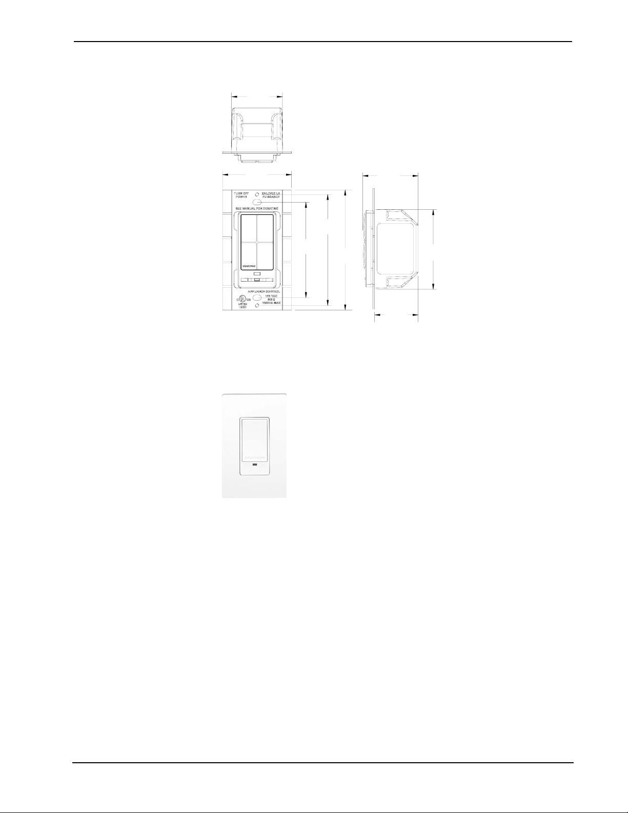
The -SLVS1RF is similar in appearance to the -SW1RF and -SWS1RF but does not
have the three-position mode selection switch. The brightness of the LED on the
-SLVS1RF is not programmable.
CLW-SLVS1RF Shown in White
6 • infiNET Switches: Crestron CLW-SW1/4RF, -SWS1/4RF, -SLVS1RF Operations Guide - DOC. 6397
Page 11
Crestron CLW-SW1/4RF, -SWS1/4RF, -SLVS1RF infiNET™ Switches
Physical View of CLW-SLVS1RF (Clockwise from Top; Top, Side, and Front)
1.75 in
(4.45 cm)
3.28 in
(8.32 cm)
3.81 in
(9.68 cm)
4.13 in
(10.48 cm)
1.88 in
(4.77 cm)
1.50 in
(3.81 cm)
2.70 in
(6.86 cm)
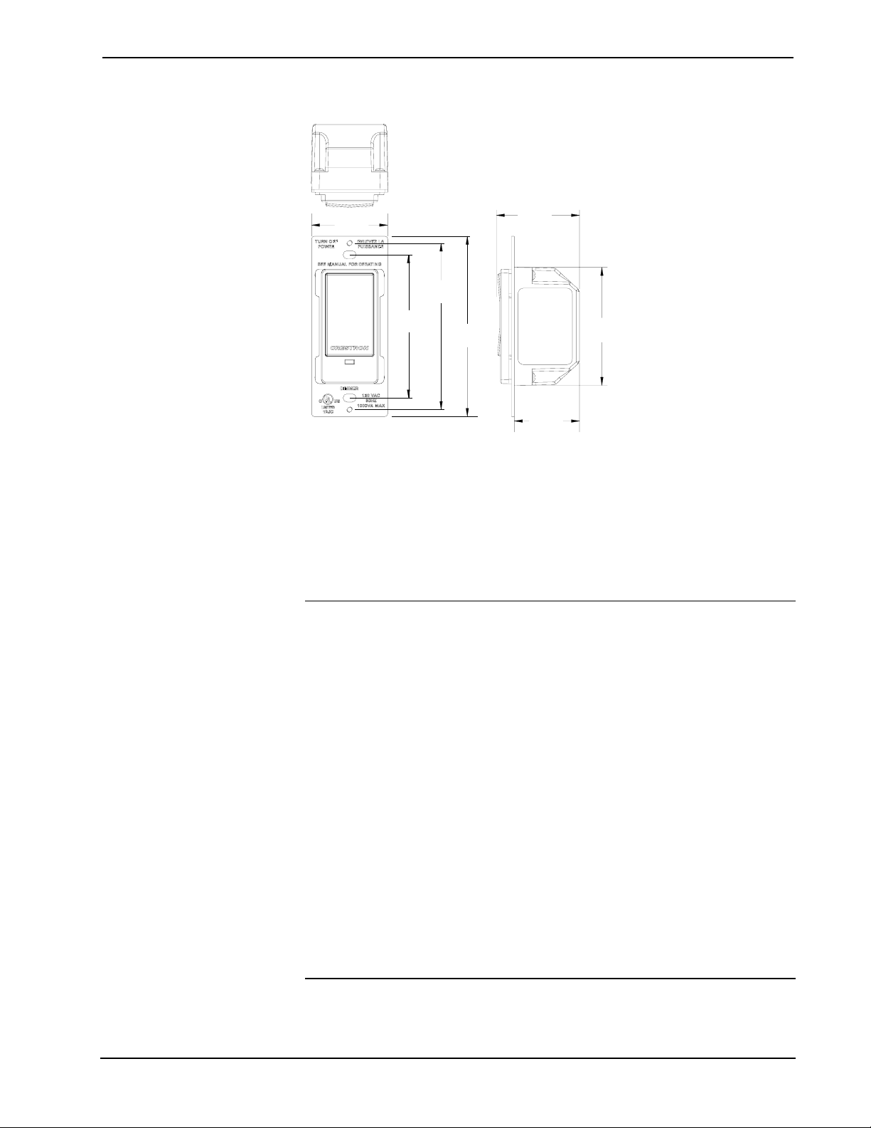
The -SW1RF, -SW4RF, -SWS1RF, -SWS4RF, and -SLVS1RF mount in a standard
wallbox and are covered using a decorative faceplate (not included). All line voltage
connections are made at the rear of the switch.
Industry Compliance
These units have been manufactured to comply with UL’s Standards for Safety in
Canada and the United States. Formal approval is pending.
FCC ID: EROCWD1011
Compliance Statement (Part 15.19 )
This device complies with Part 15 of the FCC Rules. Operation is subject to the
following two conditions:
1. This device may not cause harmful interference, and
2. This device must accept any interference received, including interference that
may cause undesired operation.
Warning (Part 15.21)
Changes or modifications not expressly approved by the party responsible for
compliance could void the user’s authority to operate the equipment.
RF Exposure (OET Bulletin 65)
To comply with FCC's RF exposure limits for general population / uncontrolled
exposure, this transmitter must be installed to provide a separation distance of at
least 20 cm from all persons and must not be co-located or operating in conjunction
with any other antenna or transmitter.
Operations Guide - DOC. 6397 infiNET Switches: Crestron CLW-SW1/4RF, -SWS1/4RF, -SLVS1RF • 7
Page 12

infiNET™ Switches Crestron CLW-SW1/4RF, -SWS1/4RF, -SLVS1RF
Industry Canada Statement
The term "IC" before the certification/registration number only signifies that the
Industry Canada technical specifications were met.
IC: 5683A-CWD1011
Acquiring the Switch on the infiNET Network
Before an infiNET device can be used on an infiNET network, it must first be
acquired to a C2N-MNETGW gateway that is connected to a Cresnet network.
NOTE: The -SW1RF, -SW4RF, -SWS1RF, and -SWS4RF can also work as standalone wall box switches without being acquired by a C2N-MNETGW.
NOTE: A switch can be acquired to only one gateway.
Acquiring the Switch
To acquire a -SW1RF/-SW4RF/-SWS1RF/-SWS4RF to C2N-MNETGW, perform
the following:
1. Put the C2N-MNETGW in the Acquire mode, from the unit itself or from
Toolbox, as described in the latest revision of the C2N-MNETGW
Operations Guide (Doc. 6137), which is available from the Crestron
website.
NOTE: In an environment where multiple gateways are installed, only one
gateway should be in the Acquire mode at a time.
2. Place the -SW1RF/-SW4RF/-SWS1RF/-SWS4RF into the Acquire mode by
doing the following:
a. Move the mode selection switch (located under the LED) to the
“OFF” position.
b. Press and hold the top or bottom of the button on the -SW1RF/
-SWS1RF or any button on the -SW4RF/-SWS4RF.
c. While holding the button, slide the mode selection switch to the
“RUN” position.
d. Hold the button for approximately five seconds until the LED
flashes HIGH once. Immediately release the button after the LED
blinks to start the dimmer’s Acquire mode.
NOTE: The LED can flash HIGH or LOW. Refer to “LED Behavior” on
page 11 for more information.
NOTE: Holding the button for a significant time after the first flash may
enter other modes. If this is not desired, return the mode selection switch to
the “OFF” position without releasing the button and repeat step 2.
After approximately ten seconds, the LED will start to blink slowly and the
switch will attempt to acquire with a C2N-MNETGW that is in the Acquire
8 • infiNET Switches: Crestron CLW-SW1/4RF, -SWS1/4RF, -SLVS1RF Operations Guide - DOC. 6397
Page 13

Crestron CLW-SW1/4RF, -SWS1/4RF, -SLVS1RF infiNET™ Switches
mode. The device is acquired when the LED stops blinking and lights at the
LOW setting. After being acquired, the device will exit the Acquire mode.
The switch will be acquired on the C2N-MNETGW with an MNET ID
value of 01.
3. Take the C2N-MNETGW out of the Acquire mode once all devices have
been acquired. Refer to the latest revision of the C2N-MNETGW
Operations Guide (Doc. 6137), which is available from the Crestron
website.
To communicate with the control system program, an MNET ID value
between 03 and 20 must be assigned to the switch. For information on
assigning MNET ID values, refer to “Identity Code” on page 12.
Removing Gateway Information from a Switch
In some rare cases, it might be desirable to release a switch from a gateway. If a
switch is to be released from a gateway, the gateway information must be cleared
from the switch’s memory.
To clear a switch’s gateway information:
1. Move the mode selection switch (located under the LED) to the “OFF”
position.
Operation
2. Press and hold the top or bottom of the button on the -SW1RF/-SWS1RF or
any button on the -SW4RF/-SWS4RF.
3. While holding the button, slide the mode selection switch to the “RUN”
position.
4. Hold the button for approximately ten seconds until the LED flashes twice.
Immediately release the button after the LED flashes twice to clear the
switch’s gateway information. Reacquire the switch if desired.
A switch can also be released from a gateway using Toolbox. Refer to the latest
revision of the C2N-MNETGW Operations Guide (Doc. 6137) for instructions.
During operation, the device may be warm to the touch during operation. This is
normal.
Mode Selection Switch
These switches use a three-position mode selection switch to set the mode of
operation.
OFF
When the mode selection switch is in the “OFF” position, the pushbutton(s) will not
have any function and the load is disconnected from the power source. This must be
used when changing light bulbs to ensure that the load is fully disconnected from
power. Slave devices that are connected to the switch will not have any function
when the Master’s mode selection switch is in the “OFF” position.
Operations Guide - DOC. 6397 infiNET Switches: Crestron CLW-SW1/4RF, -SWS1/4RF, -SLVS1RF • 9
Page 14

infiNET™ Switches Crestron CLW-SW1/4RF, -SWS1/4RF, -SLVS1RF
RUN
When the switch is in the “RUN” position, it is operating in the RUN mode. This is
the normal operating mode of the switch. The RUN mode is used to turn the load on
and off. If a delay time is set, the switch will turn off the load after the set delay time.
For information on setting a delay time, refer to “SET” below.
Refer to the following table for a list of available functions when the switch is
operating in the RUN mode.
NOTE: If the behavior of the -SW4RF/-SWS4RF has not been changed in
SIMPL™ Windows®, SystemBuilder™ or D3 Pro™, the only button that will
perform any function is Button 1. All of the other buttons are programmable.
RUN Mode Button Functions
FUNCTION -SW1RF/
-SWS1RF/
-SW4RF/-SWS4RF
BUTTON PRESS
-SLVS1RF
BUTTON PRESS
Turn on load. Tap the Top button. Tap Button 1.
Turn off load with
1,2
delay.
Cancel delayed-off
timer (if load was
already on and timer
was running).
Turn off load
immediately
1. If delay is set to 0 seconds, the load will turn off immediately.
2. If the switch was in the middle of a delay, pressing the button will cancel the delay and turn off the
load immediately.
Tap the Bottom button. Tap Button 1.
Tap the Top button. Tap Button 1.
Double-tap the Bottom
button.
Double-tap Button 1.
SET
When the mode selection switch is in the “SET” position, it is operating in the SET
mode. The LED will blink to indicate that the switch is in the SET mode. Refer to the
following table for a list of available functions when the switch is operating in this
mode.
NOTE: The SET mode is only intended for setting the delay time. Under normal
operation, the mode selection switch should be in the “RUN” position.
SET Mode Button Functions
FUNCTION -SW1RF/-SWS1RF
BUTTON PRESS
Set the delay time
to zero seconds.
Set the delay
time.*
* The button must be held for longer than three seconds in order to set the time. Any shorter time will
be ignored, and the time that was previously set will remain.
10 • infiNET Switches: Crestron CLW-SW1/4RF, -SWS1/4RF, -SLVS1RF Operations Guide - DOC. 6397
Double-tap the Bottom
button.
Press and hold the
Bottom button for the
desired amount of delay.
Upon release, the LED
will flash to confirm.
-SW4RF/-SWS4RF
BUTTON PRESS
Double-tap the Button 1.
Press and hold Button 1 for
the desired amount of delay.
Upon release, the LED will
flash to confirm.
Page 15

Crestron CLW-SW1/4RF, -SWS1/4RF, -SLVS1RF infiNET™ Switches
After setting the preset value(s), return the mode selection switch to the “RUN”
position.
-SLVS1RF
The -SLVS1RF has one rocker button. The -SLVS1RF does not have a mode
selection switch. It will emulate the RUN mode of the -SWS1RF (even if connected
to a -SWS4RF) unless the mode selection switch of the master is set to “OFF”.
Restoring Default Settings
To restore the switch’s default settings (delay time equal to zero seconds), move the
mode selection switch to the “RUN” position. While holding the pushbutton (hold
“UP” on the -SW1RF and -SWS1RF, or hold Button 1 on the -SW4RF or
-SWS4RF), move the mode selection switch to the “SET” position and back to the
“RUN” position. Release the pushbutton. The LED will flash once to confirm that
the default values have been restored.
LED Behavior
The -SW1RF, -SWS1RF, -SW4RF, and the -SWS4RF have a single amber LED. Its
behavior is determined by the current state of the switch or the control system
program.
For reference, the LED can be in one of three intensity levels: OFF, LOW, and
HIGH.
The following table describes the LED pattern in all modes of operation.
Dimmer Operation & LED Behavior
LED BEHAVIOR DEVICE STATE
LOW In RUN mode, operating normally
HIGH Device is in the bootloader. Refer to
“Bootloader” on page 37 for more
information.
Four brief OFF blinks every eight
seconds.
Four brief HIGH blinks every eight
seconds.
Two brief OFF blinks every eight
seconds.
Blink OFF for ½ second, LOW for ½
second.
Blink OFF for one second, HIGH for
one second.
Blink OFF for ¼ second, HIGH for
¼ second.
1. Refer to “Acquiring the Switch on the infiNET Network” on page 8.
2. Refer to the Crestron Toolbox help file.
In RUN mode but there is no
communication with a gateway.1
Device failed to acquire with a gateway. 1
In RUN mode, and communicating with a
gateway, but the dimmer is not addressed
in a control system program.
In SET mode.
The switch is in the Acquire mode and
searching for a gateway.
In Touch-setup mode (refer to “Using
Touch Settable ID (TSID) to Set MNET ID”
on page 12) and waiting for the user to
press a button to identify device.2
Operations Guide - DOC. 6397 infiNET Switches: Crestron CLW-SW1/4RF, -SWS1/4RF, -SLVS1RF • 11
Page 16

infiNET™ Switches Crestron CLW-SW1/4RF, -SWS1/4RF, -SLVS1RF
Identity Code
Just like every device on a Cresnet system requires a unique identity code (NET ID),
every device and user interface on the infiNET network requires a unique identity
code (MNET ID). These codes are two-digit hexadecimal numbers from 03 to 20.
The MNET ID of each unit must match an ID code specified in the SIMPL Windows
program. Refer to “Setting the MNET ID in Device Settings” on page 26 for details
of the SIMPL Windows procedure.
The MNET ID of each infiNET device has been factory set to 01. After an infiNET
device is added to an infiNET network, its MNET ID must be changed to a value that
can be addressed by the control system program (03 to 20). MNET IDs are changed
from a personal computer (PC) via the Crestron Toolbox.
NOTE: For detailed information on establishing communication between the PC,
control system, and the dimmer, refer to “Establishing Communications” on page 28.
If communication cannot be established, refer to the “Troubleshooting
Communications” section in the latest version of the 2-Series Control System
Reference Guide (Doc. 6256), which is available from the Crestron website.
The Crestron Toolbox provides several methods to easily set or change device
MNET IDs for any device on the infiNET network. MNET IDs can be set with the
touch settable ID (TSID) function or manually. To use TSID to set MNET IDs,
continue reading “Using Touch Settable ID (TSID) to Set MNET ID” below. To
manually change MNET IDs, refer to “Manually Setting the MNET ID in Crestron
Toolbox” on page 19.
Using Touch Settable ID (TSID) to Set MNET ID
Each infiNET device is shipped with the default MNET ID 01. Since 01 is an MNET
ID that cannot be addressed by the control system, the MNET ID of each infiNET
device (except C2N-MNETRPT repeaters) must be changed to a value between 03
and 20.
Using Toolbox, the SIMPL Windows program file (filename.smw) can be used in
conjunction with a device’s TSID feature to set MNET IDs of devices that were
assigned IDs in a SIMPL Windows program.
Example:
A SIMPL Windows program was saved with the filename infiNET.smw. The
program contains the following devices:
• (1) Crestron PRO2 control system
• (1) TPMC-15-CH touchpanel (NET ID 03)
• (1) C2N-MNETGW infiNET gateway (NET ID 0F)
• (2) CLW-DIM1RF infiNET dimmers (MNET IDs 03 and 0D)
• (1) CLW-SW1RF infiNET switch (MNET ID 04)
NOTE: For reference, one dimmer (MNET ID 03) is described in the example
SIMPL Windows program as “BR Dimmer” and is located in a bedroom while the
other dimmer (MNET ID 0D) is described as “LR Dimmer” and is located in the
living room.
12 • infiNET Switches: Crestron CLW-SW1/4RF, -SWS1/4RF, -SLVS1RF Operations Guide - DOC. 6397
Page 17

Crestron CLW-SW1/4RF, -SWS1/4RF, -SLVS1RF infiNET™ Switches
The infiNET switch and dimmers have already been acquired as described in the
acquiring procedure described on page 8. The devices have been assigned the default
MNET ID 01 as shown in the Network Device Tree window below.
Network Device Tree
1. With the Network Device Tree open, select Tools | SMW Program
Tree, or click
.
SMW Program Tree-Click to Select Program
2. Click the text “Click here to open program…” to select the SIMPL
Windows program that defines the MNET IDs.
Select SIMPL Windows Program
Operations Guide - DOC. 6397 infiNET Switches: Crestron CLW-SW1/4RF, -SWS1/4RF, -SLVS1RF • 13
Page 18

infiNET™ Switches Crestron CLW-SW1/4RF, -SWS1/4RF, -SLVS1RF
After selecting a file, SIMPL Windows will initialize and the SMW
Program Tree will be displayed.
SMW Program Tree
Devices with NET IDs or MNET IDs that have been identified by the
SMW Program Tree are marked with a
or MNET IDs that could not be identified are marked with a icon.
icon. Devices with NET IDs
NOTE: Descriptions such as “BR Dimmer”, “LR Dimmer”, and
“kitchen switch” were created by editing each devices symbol name in
the SIMPL Windows Programming Manager. For information on
editing a symbol name, refer to the SIMPL Windows help file.
3. Select Window | Tile Horizontally to tile the open windows in
Toolbox. To simplify viewing, only the SMW Program Tree and the
Network Device Tree described by the SMW Program Tree should be
open.
Network Device Tree and SMW Program Tree Tiled in Crestron Toolbox
14 • infiNET Switches: Crestron CLW-SW1/4RF, -SWS1/4RF, -SLVS1RF Operations Guide - DOC. 6397
Page 19

Crestron CLW-SW1/4RF, -SWS1/4RF, -SLVS1RF infiNET™ Switches
4. In the SMW Program Tree, right-click on the top level of the tree and
select Link with Network Control.
Link with Network Control
A window will be displayed with instructions for linking the SMW
Program Tree to the Network Device Tree.
Link Instruction Window
5. Click OK. The cursor will change to a target selector (
).
6. Click on the Network Device tree that is to be linked to the SMW
Program Tree, A message will be displayed indicating a successful
link.
Link Succeeded Message
7. Right-click the Lighting category in the SMW Device Tree and select
Setup All Lighting….
“Setup All Lighting…”
Operations Guide - DOC. 6397 infiNET Switches: Crestron CLW-SW1/4RF, -SWS1/4RF, -SLVS1RF • 15
Page 20

infiNET™ Switches Crestron CLW-SW1/4RF, -SWS1/4RF, -SLVS1RF
The “Setup Lighting” window will open and display a list of
unidentified lighting devices.
Setup Lighting Window
The listed devices can be sorted in ascending or descending order by
clicking on the column headers. The order can also be adjusted by
selecting a device and clicking the
when setting up devices in the order they will be encountered. For
example, when identifying devices in a home, an installer may want to
first identify a device by the entryway, then a device in the hallway,
followed by devices in a room.
Devices that do not need to be identified can be removed from the list
by clicking
NOTE: Individual devices can be set up by right-clicking the device
and selecting Setup this device. Follow the on-screen instructions to
set up the device.
8. Click Start to set up the devices in the order they appear on the list.
The first item in the list (CLW-DIM1RF, MNET ID 0D, “BR dimmer”)
will be highlighted and the upper portion of the window will indicate
the type of device.
.
or buttons. This can be used
16 • infiNET Switches: Crestron CLW-SW1/4RF, -SWS1/4RF, -SLVS1RF Operations Guide - DOC. 6397
Page 21

Crestron CLW-SW1/4RF, -SWS1/4RF, -SLVS1RF infiNET™ Switches
CLW-DIM1RF Devices in Setup Mode Window; Identifying a Device
The LEDs on all of the CLW-DIM1RF dimmers on the list will flash.
9. Physically locate the dimmer in the bedroom with the flashing LED and
touch the top or bottom of the large button. The status of the “BR
dimmer” will change from “Not Verified” to “Setup Complete” and the
next device on the list (CLW-DIM1RF, MNET ID 03, “LR dimmer”)
will be highlighted.
Touching a device may result in setting a duplicate MNET ID. A
warning will be displayed.
Duplicate MNET ID Warning
Click Yes to set the device to the duplicate MNET ID (the status will
be listed with the comment “An error occurred changing the network
ID of one or more devices.” Clicking No will skip the setup process for
that device and continue to the next device on the list.
If two devices share a duplicate MNET ID, the devices with the
duplicate MNET IDs must be set up again.
NOTE: If the device does not respond and/or register, click Skip.
Operations Guide - DOC. 6397 infiNET Switches: Crestron CLW-SW1/4RF, -SWS1/4RF, -SLVS1RF • 17
Page 22

infiNET™ Switches Crestron CLW-SW1/4RF, -SWS1/4RF, -SLVS1RF
Setup Lighting Window, Setup of First Device in List Completed
10. Continue identifying all of the remaining unidentified devices on the
list. When all devices have been identified, a summary will be
displayed in the upper portion of the window.
Setup Complete
11. Click Close to close the window once all devices have been identified.
All of the identified devices in the Network Device tree will be
indicated with the
icon as shown in the following diagram.
18 • infiNET Switches: Crestron CLW-SW1/4RF, -SWS1/4RF, -SLVS1RF Operations Guide - DOC. 6397
Page 23

Crestron CLW-SW1/4RF, -SWS1/4RF, -SLVS1RF infiNET™ Switches
Network Device Tree with Devices Set Up with SMW Program Tree
Manually Setting the MNET ID in Crestron Toolbox
The following method permits you to change the MNET ID of any infiNET device
on the infiNET network through the “Network Device Tree” window.
This method does not change the MNET ID as assigned in SIMPL Windows. For
information on setting the MNET ID in SIMPL Windows, refer to “Setting the
MNET ID in Device Settings” on page 26. If MNET IDs have already been assigned
in a SIMPL Windows program, use the Touch Settable ID method described on page
12 to change the MNET ID to match the MNET ID specified in the SIMPL Windows
program.
NOTE: You may also use D3 Pro or SystemBuilder to perform MNET ID setup.
Refer to the respective help file for more information.
1. Open Crestron Toolbox and establish communications with the control
system (refer to “Establishing Communications” on page 28).
2. Use the Network Device Tree and connect to the control system to verify
that the gateway is connected to the control system and that all infiNET
devices are acquired on the gateway. infiNET devices with MNET ID 01
will be shown with a
icon as shown in the following diagram.
Operations Guide - DOC. 6397 infiNET Switches: Crestron CLW-SW1/4RF, -SWS1/4RF, -SLVS1RF • 19
Page 24

infiNET™ Switches Crestron CLW-SW1/4RF, -SWS1/4RF, -SLVS1RF
“Network Device Tree” with Newly Added infiNET Device
3. Expand the device tree until the MNET ID that is to be changed is visible.
Right-click on the MNET ID, and when the sub-menu appears, select
Change Network ID.
“Network Device Tree” - Sub-Menu
NOTE: Any infiNET switch in the Network Device Tree can be identified
using Crestron Toolbox. Right-click a device in the Network Device Tree
and select “Identify this…”. The LED on the switch will flash HIGH. Press
a button on the switch to identify the device.
20 • infiNET Switches: Crestron CLW-SW1/4RF, -SWS1/4RF, -SLVS1RF Operations Guide - DOC. 6397
Page 25

Crestron CLW-SW1/4RF, -SWS1/4RF, -SLVS1RF infiNET™ Switches
4. Select a new MNET ID and press Enter.
Enter New MNET ID
Repeat this procedure for each additional infiNET device requiring a MNET ID
change.
WARNING: Devices with an MNET ID of 01 or 02 cannot be used in a control
system program. These devices will be indicated with a icon.
Programming Software
Have a question or comment about Crestron software?
Answers to frequently asked questions (FAQs) can be viewed in the Online Help
section of the Crestron website. To post your own question or view questions you
have submitted to Crestron’s True Blue Support, log in at
http://support.crestron.com
Setup is easy thanks to Crestron’s Windows-based programming software.
Crestron’s D3 Pro software or SystemBuilder software can create a complete project,
with no special programming required. While traditional programming tools can still
be used to program a system, D3 Pro and SystemBuilder can be used to easily
complete all necessary programming for a base system including all touchpanel
screens and the control system program. The program output of D3 Pro and
SystemBuilder is a SIMPL Windows program with much of the functionality
encapsulated in macros and templates. Once D3 Pro and/or Systembuilder creates the
project, the system interfaces and program logic can be customized in D3 Pro and/or
Systembuilder or can be easily modified with Crestron development tools (i.e.,
SIMPL Windows and Crestron VisionTools® Pro-e (VT Pro-e) software packages).
. First-time users will need to establish a user account.
D3 Pro and SystemBuilder come with templates for all supported interfaces. If a user
wishes to create a touchpanel project using templates with a different look-and-feel,
this can be accomplished by making a custom template. This custom template can
then be used by D3 Pro or SystemBuilder to create the final project files to be loaded
Operations Guide - DOC. 6397 infiNET Switches: Crestron CLW-SW1/4RF, -SWS1/4RF, -SLVS1RF • 21
Page 26

infiNET™ Switches Crestron CLW-SW1/4RF, -SWS1/4RF, -SLVS1RF
p
into the panels. Alternatively, VT Pro-e can be used to tweak projects created with
the D3 Pro and/or SystemBuilder or develop original touchpanel screen designs.
NOTE: Crestron recommends the use of D3 Pro or SystemBuilder for programming
an infiNET system.
Earliest Version Software Requirements for the PC
NOTE: Crestron recommends that you use the latest software to take advantage of
the most recently released features. The latest software is available from the Crestron
website.
The following are the minimum recommended software versions for the PC running
Windows XP or Windows 2000:
• SIMPL Windows version 2.06.20 or later with library update 352 or later.
Requires SIMPL+ Cross Compiler version 1.1 or later.
• Crestron Toolbox 1.02.06 or later
• Crestron Database version 17.3.3 or later. Required by SIMPL Windows.
The easiest method of
rogramming, but does not
offer as much flexibility as
SIMPL Windows.
• (Optional) D3 Pro version 2.0 or later. Also requires:
o D3 Pro Templates 1.0 or later
o VisionTools Pro-e 3.3.3.5 or later
o Crestron Database 17.3.3 or later
o Crestron Engraver 2.2.2.3 or later
o CUZ 3.154 for 2-Series processors or later
• (Optional) SystemBuilder version 2.0 or later with SystemBuilder
Templates version 2.0.1or later. Also requires:
o VisionTools Pro-e 3.3.4.0 or later
o Crestron Engraver 2.4.1.2 or later
o CUZ 3.154 for 2-Series processors or later
Programming with D3 Pro & SystemBuilder
D3 Pro and SystemBuilder offer automatic programming for such residential
and commercial applications as audio distribution, home theater, video
conferencing, and lighting. The interface of this tool guides you through a few
basic steps for designating rooms and specifying the control system,
touchpanels, devices, and functionality. D3 Pro and SystemBuilder then
program the system, including touchpanel projects and control system logic.
D3 Pro and SystemBuilder are fully integrated with Crestron's suite of software
development tools, including SIMPL Windows, VT Pro-e, and the Crestron
Database. D3 Pro and SystemBuilder access these tools behind the scenes, enabling
you to easily create robust systems.
22 • infiNET Switches: Crestron CLW-SW1/4RF, -SWS1/4RF, -SLVS1RF Operations Guide - DOC. 6397
Page 27

Crestron CLW-SW1/4RF, -SWS1/4RF, -SLVS1RF infiNET™ Switches
Programming with SIMPL Windows
NOTE: The following assumes that the reader has knowledge of SIMPL Windows.
If not, refer to the extensive help information provided with the software.
NOTE: The following are acceptable file extensions for programs that include a
infiNET switch, developed for specific control system types:
.smw: projectname.smw (SIMPL Windows source file)
.spz: projectname.spz (compiled file for 2-series)
NOTE: In the following description, the PAC2 control system is used.
SIMPL Windows is Crestron's software for programming Crestron control systems.
It provides a well-designed graphical environment with a number of workspaces
(i.e., windows) in which a programmer can select, configure, program, test, and
monitor a Crestron control system. SIMPL Windows offers drag and drop
functionality in a familiar Windows® environment.
This section describes a sample SIMPL Windows program that includes a
C2N-MNETGW gateway and CLW-SW1RF switch.
PAC2 System View
Configuration Manager is where programmers “build” a Crestron control system by
selecting hardware from the Device Library. In Configuration Manager, drag the
PAC2 from the Control Systems folder of the Device Library and drop it in the upper
pane of the System Views. The PAC2 with its associated communication ports is
displayed in the System Views upper pane.
The System Views lower pane displays the PAC2 system tree. This tree can be
expanded to display and configure the communications ports.
Expanded PAC2 System Tree
Operations Guide - DOC. 6397 infiNET Switches: Crestron CLW-SW1/4RF, -SWS1/4RF, -SLVS1RF • 23
Page 28

infiNET™ Switches Crestron CLW-SW1/4RF, -SWS1/4RF, -SLVS1RF
C2Net-Device Slot in Configuration Manager
Before adding an infiNET switch to a system, a C2N-MNETGW must first be added.
To incorporate a C2N-MNETGW into the system, drag the symbol from the
Wireless Receivers |Wireless Receivers (RF) folder of the Device Library and drop it
in the System Views. The PAC2 system tree displays the C2N-MNETGW in slot 6
with a default Net ID of 0F as shown in the following illustration.
C2Net Device, Slot 6
NOTE: The first C2N-MNETGW in a system is preset with a Net ID of 0F when its
symbol is dragged into the upper pane of System Views. Additional units are assigned
different Net ID numbers as they are added. For more information on the Net ID of a
C2N-MNETGW, refer to the latest revision of the C2N-MNETGW Operations
Guide (Doc. 6137), which is available from the Crestron website.
Setting the Net ID in Device Settings
Double-click the C2N-MNETGW icon to open the “Device Settings” window. This
window displays the gateway device information. If necessary, select the Net ID tab
to change the Net ID, as shown in the following figure.
“Device Settings” Window for the C2N-MNETGW
NOTE: SIMPL Windows automatically changes Net ID values of a device added to
a program if a duplicate device or a device with the same default Net ID already
24 • infiNET Switches: Crestron CLW-SW1/4RF, -SWS1/4RF, -SLVS1RF Operations Guide - DOC. 6397
Page 29

Crestron CLW-SW1/4RF, -SWS1/4RF, -SLVS1RF infiNET™ Switches
exists in the program. Always ensure that the hardware and software settings of the
Net ID match. For Net ID hardware settings details, refer to “Identity Code” on page
12.
Adding infiNET Devices to the C2N-MNETGW
To add infiNET devices to the C2N-MNETGW, right click on the C2N-MNETGW,
select Add item to: “C2N-MNETGW” and select an infiNET device as shown in
the following diagram.
Adding an infiNET Device to the C2N-MNETGW
SIMPL Windows adds the selected infiNET device with a default MNET ID.
Following are the default MNET IDs used by SIMPL Windows for each of the
switch models:
• CLW-SW1RF: 07
• CLW-SW4RF: 09
• CLW-SWS1RF: 08
• CLW-SWS4RF: 0A
NOTE: The default MNET ID used by SIMPL Windows is different from the
default ID that is installed on an infiNET device when it ships from the factory.
NOTE: If the default MNET ID is already in use, SIMPL Windows will assign the
next available MNET ID.
NOTE: infiNET repeaters such as the C2N-MNETRPT are not added in SIMPL
Windows as there is no control communication between a control system and a
repeater.
Operations Guide - DOC. 6397 infiNET Switches: Crestron CLW-SW1/4RF, -SWS1/4RF, -SLVS1RF • 25
Page 30

infiNET™ Switches Crestron CLW-SW1/4RF, -SWS1/4RF, -SLVS1RF
C2Net Device, Slot 9, with infiNET Device
Setting the MNET ID in Device Settings
Double-click the CLW-SW1RF icon to open the “Device Settings” window. This
window displays the CLW-SW1RF device information. If necessary, select the
RF/IR ID tab to change the MNET ID, as shown in the following figure.
“Device Settings” Window for the CLW-SW1RF
NOTE: SIMPL Windows automatically changes MNET ID values of a device
added to a program if a duplicate device or a device with the same default MNET ID
already exists in the program. Always ensure that the hardware and software settings
of the MNET ID match. For MNET ID hardware settings details, refer to “Identity
Code” on page 12.
infiNET Switch Symbols in Programming Manager
Programming Manager is where programmers “program” a Creston control system
by assigning signals to symbols.
For more information on the symbols, refer to the SIMPL Windows help file.
26 • infiNET Switches: Crestron CLW-SW1/4RF, -SWS1/4RF, -SLVS1RF Operations Guide - DOC. 6397
Page 31

Crestron CLW-SW1/4RF, -SWS1/4RF, -SLVS1RF infiNET™ Switches
Attaching and Detaching the Electrical Load
The buttons on the switch can be attached (default) or detached from the electrical
load. When attached to the electrical load, the electrical load is controlled by the
button’s built-in functionality, i.e. the buttons on the switch control the electrical
load directly. When the buttons are detached from the electrical load, the control
system program defines the function of each button. The buttons can be programmed
in SIMPL Windows to control the electrical load or to perform another function in
the control system program.
NOTE: If a detached device restarts from either a power failure or from moving the
mode selection switch from the “OFF” position, the device will be attached to the
electrical load until communication with the gateway is reestablished (approximately
15-20 seconds).
The buttons on the switch can be attached and detached from the electrical load
using the switch’s programming symbol. For more information on attaching and
detaching the load, refer to the switch symbol’s SIMPL Windows help file.
Operations Guide - DOC. 6397 infiNET Switches: Crestron CLW-SW1/4RF, -SWS1/4RF, -SLVS1RF • 27
Page 32

infiNET™ Switches Crestron CLW-SW1/4RF, -SWS1/4RF, -SLVS1RF
Uploading and Upgrading
NOTE: Crestron recommends using the latest programming software and that each
device contains the latest firmware to take advantage of the most recently released
features. Please check the Crestron website (http://www.crestron.com/updates) for
the latest versions of software and firmware. New users are required to register to
obtain access to this site.
Assuming a PC is properly connected to the entire system, Crestron programming
software allows the programmer to upload programs, projects and firmware to the
system and touchpanels after their development. However, there are times when the
files for the program and projects are compiled and not uploaded. Instead, compiled
files may be distributed from programmers to installers, from Crestron to dealers,
etc. Even firmware upgrades are available from the Crestron website as new features
are developed after product releases. In those instances, one has the option to upload
via the programming software or to upload and upgrade via the Crestron Toolbox.
The following sections define how one would upload a SIMPL Windows program to
the control system and upgrade the firmware of CLW-SW1RF/-SWS1RF/-SW4RF/
-SWS4RF. However, before attempting to upload or upgrade, it is necessary to
establish communications between the PC and the dimmer.
Establishing Communications
The procedure in this section provides details for RS-232 communication between a
PC and a switch via the control system and C2N-MNETGW. This method can be
used to communicate with the control system directly, with a C2N-MNETGW via
the control system’s Cresnet connection, and a switch via the C2N-MNETGW
connected to the control system. If TCP/IP communication is preferred, consult the
latest version of the Crestron e-Control Reference Guide (Doc. 6052) or the
respective Operations Guide for the control system. These documents are available
from the Crestron website. Refer to the following figure for a typical connection
diagram when connecting to a switch via a C2N-MNETGW that is connected to a
control system. In this example, the PC communicates with the control system via
RS-232.
Indirect Serial Communications Setup Connections
28 • infiNET Switches: Crestron CLW-SW1/4RF, -SWS1/4RF, -SLVS1RF Operations Guide - DOC. 6397
Page 33

Crestron CLW-SW1/4RF, -SWS1/4RF, -SLVS1RF infiNET™ Switches
1. Ensure that all devices are connected to the control system and the control
system is connected via serial cable to the PC. The dimmer should also be
acquired on the C2N-MNETGW through the acquire procedure described
on page 8.
2. Open Crestron Toolbox and click Tools | Manage Address Book to display
a list of available addresses. Select a connection to a control system (if an
entry for one exists), or Serial on COM1 as the connection type. Serial on
COM1 is an address book entry for PC-to-control system communications
that is included with the default address book of Crestron Toolbox.
3. The PC communication settings specified here should match the protocol
that the control system expects. The usual settings are as follows:
• Port = COM 1 through COM 8. Select the correct COM port on the
PC.
• Baud rate = Auto-detect.
• Parity = None.
• Number of data bits = 8.
• Number of stop bits = 1.
• Hardware handshaking (RTS/CTS) enabled.
• Software handshaking (XON/XOFF) not enabled.
“Address Book” Window - Serial Setup
4. After setting the correct parameters, click OK to return to the Crestron
Toolbox main window.
5. Click Tools | Network Device Tree, or click the network device tree icon
to display the devices in the system. Select the entry for the control
system or Serial on COM1 from the drop down list at the bottom of the
window if it is not already selected. If communication is successful, the
network devices that are connected to the control system are displayed. If
Operations Guide - DOC. 6397 infiNET Switches: Crestron CLW-SW1/4RF, -SWS1/4RF, -SLVS1RF • 29
Page 34

infiNET™ Switches Crestron CLW-SW1/4RF, -SWS1/4RF, -SLVS1RF
no devices are reported, verify the connections between the control system
and the devices that are connected to it. If infiNET devices are not listed,
verify that they have been acquired as described in the acquire procedure on
page 8.
Network Device Tree
To view a specific device, expand the network device tree by clicking +.
Expand the network device tree until the device to be managed is selected.
Right-click the desired MNET ID to open the sub-menu. This menu
provides a wide range of functions, including; change the MNET ID,
change serial number, update firmware, etc.
Network Device Tree Sub-Menu-Functions
NOTE: Toolbox displays a customized list of functions depending on the
type of device with which it is communicating.
30 • infiNET Switches: Crestron CLW-SW1/4RF, -SWS1/4RF, -SLVS1RF Operations Guide - DOC. 6397
Page 35

Crestron CLW-SW1/4RF, -SWS1/4RF, -SLVS1RF infiNET™ Switches
Troubleshooting Communications
Use the following checklist if communication cannot be established with the control
system.
1. Verify that the correct cables are used. Refer to the control systems
Operations Guide for information about RS-232 cables.
2. With a serial connection, verify that the correct COM port on the PC has
been selected. Some computers have more than one COM port; some may
be internal (e.g., for a modem). Consult the manufacturer’s documentation
for further information about the COM ports on your PC.
3. Remove and reapply power to the control system.
4. If communication still cannot be established, contact Crestron customer
service.
Use the following checklist if communication cannot be established with the infiNET
device.
1. Verify that the infiNET device is connected to line power and the
C2N-MNETGW is connected to the control system.
2. Reacquire the infiNET device on the C2N-MNETGW. Refer to “Acquiring
the Switch on the infiNET Network” on page 8 for more information. Also
refer to the latest version of the C2N-MNETGW Operations Guide (Doc.
6317), which is available from the Crestron website.
3. If communication still cannot be established, contact Crestron customer
service.
Uploading a SIMPL Windows Program
The SIMPL Windows file can be uploaded to the control system using SIMPL
Windows or via Crestron Toolbox.
Upload via SIMPL Windows
1. Start SIMPL Windows.
2. Select File | Open to view the “Open” window, navigate to the SIMPL
Window file (.smw), and click Open.
3. Select Project | Transfer Program.
Upload via Crestron Toolbox
1. Verify that the procedure for “Establishing Communications” that begins on
page 28 has been performed to establish a connection between the PC and
the control system.
2. Open Crestron Toolbox and select Tools | System Info.
Operations Guide - DOC. 6397 infiNET Switches: Crestron CLW-SW1/4RF, -SWS1/4RF, -SLVS1RF • 31
Page 36

infiNET™ Switches Crestron CLW-SW1/4RF, -SWS1/4RF, -SLVS1RF
Crestron Toolbox - Tools | System Info
3. Select the entry for the control system or Serial on COM1 from the drop
down list at the bottom of the window if it is not already selected. When the
“System Info” window appears and you are connected to the control
system, the Functions option becomes available from the menu bar.
4. Select Functions | SIMPL Program.
The “SIMPL Program” window contains information about the currently
loaded SIMPL program (if any), and permits you to stop, start, erase,
retrieve, and upload a SIMPL program. This menu also permits you to
upload to compact flash or internal flash.
“SIMPL Program” Window
32 • infiNET Switches: Crestron CLW-SW1/4RF, -SWS1/4RF, -SLVS1RF Operations Guide - DOC. 6397
Page 37

Crestron CLW-SW1/4RF, -SWS1/4RF, -SLVS1RF infiNET™ Switches
5. Click the button to browse for a new compiled (.spz) program.
“Open” Window
6. Select a file and click Open. When the “SIMPL Program” window re-opens
click Send.
Operations Guide - DOC. 6397 infiNET Switches: Crestron CLW-SW1/4RF, -SWS1/4RF, -SLVS1RF • 33
Page 38

infiNET™ Switches Crestron CLW-SW1/4RF, -SWS1/4RF, -SLVS1RF
Firmware Upgrade
To take advantage of all the device features, it is important that the unit contains the
latest firmware available. Please check the Crestron website for the latest version of
firmware. Not every product has a firmware upgrade, but as Crestron improves
functions, adds new features, and extends the capabilities of its products, firmware
upgrades are posted. To upgrade the firmware, complete the following steps.
1. Verify that the procedure for “Establishing Communications” that begins on
page 28 has been performed.
2. Open Crestron Toolbox and open the Network Device Tree (the firmware
upgrade function is also available in the SMW Program Tree window).
3. Right-click on the device and select Functions | Firmware.
Network Device Tree Window - Right-Click Sub Menu
4. The “Firmware” window displays the model and current firmware version.
Click Upload New Firmware.
“Firmware” Window
5. Click Browse… to find a firmware file to send to the device.
34 • infiNET Switches: Crestron CLW-SW1/4RF, -SWS1/4RF, -SLVS1RF Operations Guide - DOC. 6397
Page 39

Crestron CLW-SW1/4RF, -SWS1/4RF, -SLVS1RF infiNET™ Switches
6. When the following screen appears, browse to locate the firmware (.zip)
file.
Locate Firmware in the “Open” Window
7. Click Open to select the file.
8. The “Firmware” window reopens indicating the target device, the new
firmware version, and release notes information. Click View… to view the
release notes, or click Send to upgrade the firmware. Click Close after the
firmware has been transferred.
Operations Guide - DOC. 6397 infiNET Switches: Crestron CLW-SW1/4RF, -SWS1/4RF, -SLVS1RF • 35
Page 40

infiNET™ Switches Crestron CLW-SW1/4RF, -SWS1/4RF, -SLVS1RF
Problem Solving
Troubleshooting
The table after this paragraph provides corrective action for possible trouble
situations. If further assistance is required, please contact a Crestron customer
service representative.
infiNET Switch Troubleshooting
TROUBLE POSSIBLE CAUSE(S) CORRECTIVE ACTION
Switch does
not function.
Switch does
not respond
to control
system
commands.
Switch is not receiving line
power.
Load is not connected.
Mode selection switch is in
the “SET” position.
If the LED flashes OFF for ¼
second four times, then
returns to low every eight
seconds, the switch is not
acquired on infiNET network.
If the LED flashes OFF for ¼
second two times, then
returns to low, the MNET ID of
device is not set to match the
MNET ID of the SIMPL
Windows program.
If the LED flashes OFF for ¼
second four times, then
returns to low every eight
seconds, the C2N-MNETGW
is not transmitting data to the
infiNET device.
Verify that the switch is
properly connected to the
power lines and that the
circuit breaker is closed.
Verify that the load is
operational and that the mode
selection switch is in the
“RUN” or “SET” position.
Move mode selection switch
to the “RUN” position.
Use the Network Device Tree
infiNET network in Crestron
Toolbox to poll the infiNET
network. Acquire the device
on infiNET network as
described in “Acquiring the
Switch on the infiNET
Network” on page 8.
Use the Network Device Tree
infiNET network in Crestron
Toolbox to poll the infiNET
network. Verify that the MNET
ID for the infiNET device is set
to match the MNET ID
specified in the SIMPL
Windows program.
Open Crestron Toolbox and
select the Network Device
tree. Expand the network
device tree until the gateway
to be managed is selected.
Right-click the Net ID of the
selected gateway to open the
sub-menu and select
Functions|MNET
Gateway…. If devices are not
listed, acquire the device on
to the infiNET network as
described in “Acquiring the
Switch on the infiNET
Network” on page 8.
(continued on following page)
36 • infiNET Switches: Crestron CLW-SW1/4RF, -SWS1/4RF, -SLVS1RF Operations Guide - DOC. 6397
Page 41

Crestron CLW-SW1/4RF, -SWS1/4RF, -SLVS1RF infiNET™ Switches
infiNET Switch Troubleshooting (continued)
TROUBLE POSSIBLE CAUSE(S) CORRECTIVE ACTION
Switch
presses are
not reported
to control
system.
Switch does
not operate
as described
in the
manual.
Delay time
will not store.
Cannot turn
the load on
or off.
Slave device
does not
emulate the
RUN mode
of the
-SWS1RF
(even when
connected to
-SWS4RF).
If the LED flashes OFF for
¼ second two times, then
returns to low, the MNET ID
of device is not set to match
the MNET ID of the SIMPL
Windows program.
If the LED flashes OFF for
¼ second four times, then
returns to low every eight
seconds, the infiNET device
is not transmitting data to
the C2N-MNETGW.
Switch is attached to load
and the signal
Enable_Local_Btn_Outputs
is low.
Switch is detached from the
load.
Mode selection switch is in
the incorrect position.
Mode selection switch is in
the incorrect position.
-SLVS1RF is detached from
the load.
Using Crestron Toolbox, poll
the network. Verify that the
MNET ID for the infiNET
device is set to match the
MNET ID specified in the
SIMPL Windows program.
Open Crestron Toolbox and
select the Network Device
tree. Expand the network
device tree until the gateway
to be managed is selected.
Right-click the Net ID of the
selected gateway to open the
sub-menu and select
Functions|MNET
Gateway…. If devices are not
listed, add devices by putting
the C2N-MNETGW and
infiNET device in Acquire
mode.
In the switch symbol of the
SIMPL Windows program, set
the signal
Enable_Local_Btn_Outputs
high.
In the switch symbol of the
SIMPL Windows program, set
the signal Detach_Load low.
Set the mode selection switch
to the “SET” position to store
the delay time.
Set the mode selection switch
to the “RUN” position to turn
the load on or off.
Set the signal
Detach_Load_From_Slave
low.
Bootloader
In rare cases, it may be necessary to bypass the switch’s standard firmware and enter
into the “bootloader”. This might be necessary if the unit was loaded with a faulty
version of firmware that might prevent future firmware upgrades.
To enter the bootloader, set the mode selection switch to “OFF”. Press and hold the
up button (or Button 1 on the -SW4RF or -SWS4RF) while setting the mode
selection switch to “RUN”. The LED will blink once after five seconds to indicate
Operations Guide - DOC. 6397 infiNET Switches: Crestron CLW-SW1/4RF, -SWS1/4RF, -SLVS1RF • 37
Page 42

infiNET™ Switches Crestron CLW-SW1/4RF, -SWS1/4RF, -SLVS1RF
the start of Acquire mode (Acquire mode does not actually start until you release the
button). Continue holding the button for another five seconds, and the LED will flash
twice to indicate that the gateway connection will be released on the release of the
button. Continue holding the button an additional ten seconds (20 seconds in all)
until the LED flashes three times and release the button. The unit is now running the
bootloader. New firmware can now be uploaded from Crestron Toolbox.
To exit the bootloader and restore the firmware that is currently installed, cycle
power to the device by setting the mode selection switch to “OFF” and back to
“RUN” or “SET”.
Further Inquiries
If you cannot locate specific information or have questions after reviewing this
guide, please take advantage of Crestron's award winning customer service team by
calling the Crestron corporate headquarters at 1-888-CRESTRON [1-888-273-7876].
For assistance in your local time zone, refer to the Crestron website
(www.crestron.com
You can also log onto the online help section of the Crestron website to ask
questions about Crestron products. First-time users will need to establish a user
account to fully benefit from all available features.
) for a listing of Crestron worldwide offices.
Future Updates
As Crestron improves functions, adds new features, and extends the capabilities of
the device, additional information may be made available as manual updates. These
updates are solely electronic and serve as intermediary supplements prior to the
release of a complete technical documentation revision.
Check the Crestron website periodically for manual update availability and its
relevance. Updates are identified as an “Addendum” in the Download column.
38 • infiNET Switches: Crestron CLW-SW1/4RF, -SWS1/4RF, -SLVS1RF Operations Guide - DOC. 6397
Page 43

Crestron CLW-SW1/4RF, -SWS1/4RF, -SLVS1RF infiNET™ Switches
Return and Warranty Policies
Merchandise Returns / Repair Service
1. No merchandise may be returned for credit, exchange, or service without prior
authorization from CRESTRON. To obtain warranty service for CRESTRON products,
contact the factory and request an RMA (Return Merchandise Authorization) number.
Enclose a note specifying the nature of the problem, name and phone number of contact
person, RMA number, and return address.
2. Products may be returned for credit, exchange, or service with a CRESTRON Return
Merchandise Authorization (RMA) number. Authorized returns must be shipped freight
prepaid to CRESTRON, 6 Volvo Drive, Rockleigh, N.J., or its authorized subsidiaries,
with RMA number clearly marked on the outside of all cartons. Shipments arriving
freight collect or without an RMA number shall be subject to refusal. CRESTRON
reserves the right in its sole and absolute discretion to charge a 15% restocking fee, plus
shipping costs, on any products returned with an RMA.
3. Return freight charges following repair of items under warranty shall be paid by
CRESTRON, shipping by standard ground carrier. In the event repairs are found to be
non-warranty, return freight costs shall be paid by the purchaser.
CRESTRON Limited Warranty
CRESTRON ELECTRONICS, Inc. warrants its products to be free from manufacturing defects in
materials and workmanship under normal use for a period of three (3) years from the date of purchase
from CRESTRON, with the following exceptions: disk drives and any other moving or rotating
mechanical parts, pan/tilt heads and power supplies are covered for a period of one (1) year;
touchscreen display and overlay components are covered for 90 days; batteries and incandescent lamps
are not covered.
This warranty extends to products purchased directly from CRESTRON or an authorized CRESTRON
dealer. Purchasers should inquire of the dealer regarding the nature and extent of the dealer's warranty,
if any.
CRESTRON shall not be liable to honor the terms of this warranty if the product has been used in any
application other than that for which it was intended, or if it has been subjected to misuse, accidental
damage, modification, or improper installation procedures. Furthermore, this warranty does not cover
any product that has had the serial number altered, defaced, or removed.
This warranty shall be the sole and exclusive remedy to the original purchaser. In no event shall
CRESTRON be liable for incidental or consequential damages of any kind (property or economic
damages inclusive) arising from the sale or use of this equipment. CRESTRON is not liable for any
claim made by a third party or made by the purchaser for a third party.
CRESTRON shall, at its option, repair or replace any product found defective, without charge for parts
or labor. Repaired or replaced equipment and parts supplied under this warranty shall be covered only
by the unexpired portion of the warranty.
Except as expressly set forth in this warranty, CRESTRON makes no other warranties, expressed or
implied, nor authorizes any other party to offer any warranty, including any implied warranties of
merchantability or fitness for a particular purpose. Any implied warranties that may be imposed by law
are limited to the terms of this limited warranty. This warranty statement supercedes all previous
warranties.
Trademark Information
All brand names, product names, and trademarks are the sole property of their respective owners. Windows is a registered
trademark of Microsoft Corporation. Windows95/98/Me/XP and WindowsNT/2000 are trademarks of Microsoft Corporation.
Operations Guide - DOC. 6397 infiNET Switches: Crestron CLW-SW1/4RF, -SWS1/4RF, -SLVS1RF • 39
Page 44

Crestron Electronics, Inc. Operations Guide – DOC. 6397
15 Volvo Drive Rockleigh, NJ 07647 (2014134)
Tel: 888.CRESTRON 12.05
Fax: 201.767.7576 Specifications subject to
www.crestron.com change without notice.
 Loading...