

Page 1
Functional Summary
The Crestron® CLTIBN-BLANK Terminal Block for
Breakers allows the installation of DIN rail-mounted
branch circuit breakers (supplied by others) in a Crestron
CAENIB automation enclosure. Every CLTIBN-BLANK
includes covers for unoccupied slots on the DIN rail and a
door kit that is installed on the cover of the CAENIB
enclosure. This door kit allows access to the circuit
breakers located on the CLTIBN-BLANK without
removing the cover of the CAENIB enclosure. An
adhesive label is also provided for identifying controlled
circuits.
Industry Compliance
This product complies with the essential requirements of
all applicable EU directives.
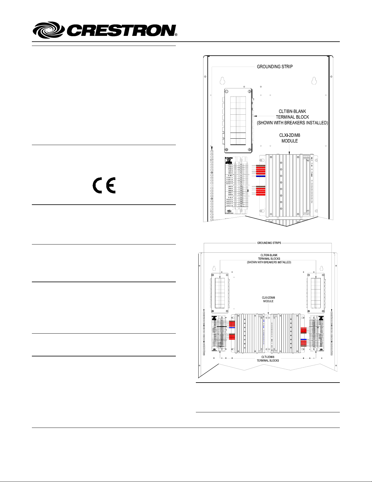
CLTIBN-BLANK
Terminal Block & Module Locations (Single-wide Enclosure)
Installation
The terminal block must be mounted into a CAENIB
Enclosure by a licensed electrician, in accordance with all
national and local codes.
CAUTION: This equipment is for indoor use only and
needs to be air-cooled. Mount in a well-ventilated area.
The ambient temperature must be 0°C to 40°C (32°F to
104°F). The relative humidity must be 0% to 90% (noncondensing).
Terminal blocks are installed along the left side of singlewide enclosures and along the outside edges (left and
right sides) of double-wide enclosures. Refer to the
illustrations shown in the next column when considering
the location of terminal blocks and modules within an
enclosure.
NOTE: To insure proper fit, terminal blocks must be
installed at the locations indicated in the latest version of
the CAENIB Installation Guide.
Terminal Block & Module Locations (Double-wide Enclosure)
NOTE: Unless otherwise indicated, the lighting system
specified in this guide is modular, requiring assembly in
the field by a licensed electrician, in accordance with all
national and local codes.
Crestron Electronics, Inc. Installation Guide – DOC. 6586A
15 Volvo Drive Rockleigh, NJ 07647 (2018015)
Tel: 888.CRESTRON 05.07
Fax: 201.767.7576 Specifications subject to
www.crestron.com change without notice.
Page 2
Terminal Block for Breakers Crestron CLTIBN-BLANK
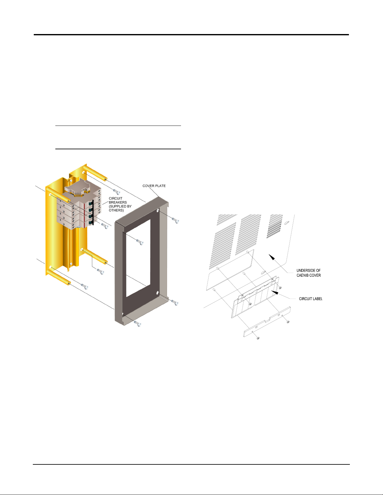
Breaker Installation
Using the diagram below as reference, install DIN railmounted circuit breakers in the CLTIBN-BLANK.
1. Using a Phillips screwdriver, remove the four
screws securing the cover plate to the
CLTIBN-BLANK and remove the cover plate.
2. Mount DIN rail-mounted circuit breakers and
other DIN rail components on to the
CLTIBN-BLANK’s DIN rail.
NOTE: All DIN rail components must be
installed and connected according to
manufacturer’s specifications.
CLTIBN-BLANK Exploded View
5. Grounding terminal blocks are available in the
cabinet for termination of ground wires. Tighten
to 4 Nm (2.5 - 6.0 mm
5.1 Nm (16 - 25 mm2).
6. Replace the cover plate that was removed during
step 1 of the installation procedure.
7. Insert plastic covers into unoccupied slots.
2
), 4.5 Nm (10.0 mm2), or
Access Door Installation
After the terminal block has been installed and
successfully tested, the access door must be installed on
the CAENIB’s cover in the location of the terminal block.
1. If a blank plate is installed, remove it by
removing the nuts that secure the plate to the
CAENIB cover. Remove the plate from the
mounting studs on the CAENIB cover.
2. Install the access door assembly as shown in the
following diagram.
Install Access Door Assembly (Underside of CAENIB Cover
shown)
3. Use the four supplied self-tapping pan Phillips
screws (8B x ¼-inch (6 mm) length) to secure
the terminal block to the Crestron Automation
Enclosure.
4. Make all required connections to the circuit
breakers.
2 • Terminal Block for Breakers: CLTIBN-BLANK Installation Guide – DOC. 6586A
3. Secure the door assembly to the CAENIB cover,
by tightening the included nuts.
4. Open the access door and affix the included
blank circuit label to the door. Label the circuits
as required.
Page 3

Crestron CLTIBN-BLANK Terminal Block for Breakers
Return and Warranty Policies
Further Inquiries
If you cannot locate specific information or have
questions after reviewing this guide, please take
advantage of Crestron's award winning customer service
team by calling the Crestron corporate headquarters at
1-888-CRESTRON [1-888-273-7876]. For assistance in
your local time zone, refer to the Crestron website
(http://www.crestron.com/offices
worldwide offices.
You can also log onto the online help section of the
Crestron website (http://www.crestron.com/onlinehelp
ask questions about Crestron products. First-time users
will need to establish a user account to fully benefit from
all available features.
) for a listing of Crestron
) to
Merchandise Returns / Repair Service
1. No merchandise may be returned for credit, exchange or service
without prior authorization from CRESTRON. To obtain
warranty service for CRESTRON products, contact an authorized
CRESTRON dealer. Only authorized CRESTRON dealers may
contact the factory and request an RMA (Return Merchandise
Authorization) number. Enclose a note specifying the nature of
the problem, name and phone number of contact person, RMA
number and return address.
2. Products may be returned for credit, exchange or service with a
CRESTRON Return Merchandise Authorization (RMA) number.
Authorized returns must be shipped freight prepaid to
CRESTRON, 6 Volvo Drive, Rockleigh, N.J. or its authorized
subsidiaries, with RMA number clearly marked on the outside of
all cartons. Shipments arriving freight collect or without an RMA
number shall be subject to refusal. CRESTRON reserves the right
in its sole and absolute discretion to charge a 15% restocking fee
plus shipping costs on any products returned with an RMA.
3. Return freight charges following repair of items under warranty
shall be paid by CRESTRON, shipping by standard ground
carrier. In the event repairs are found to be non-warranty, return
freight costs shall be paid by the purchaser.
CRESTRON Limited Warranty
CRESTRON ELECTRONICS, Inc. warrants its products to be free from
manufacturing defects in materials and workmanship under normal use
for a period of three (3) years from the date of purchase from
CRESTRON, with the following exceptions: disk drives and any other
moving or rotating mechanical parts, pan/tilt heads and power supplies
are covered for a period of one (1) year; touchscreen display and overlay
components are covered for 90 days; batteries and incandescent lamps
are not covered.
This warranty extends to products purchased directly from CRESTRON
or an authorized CRESTRON dealer. Purchasers should inquire of the
dealer regarding the nature and extent of the dealer's warranty, if any.
CRESTRON shall not be liable to honor the terms of this warranty if the
product has been used in any application other than that for which it was
intended or if it has been subjected to misuse, accidental damage,
modification or improper installation procedures. Furthermore, this
warranty does not cover any product that has had the serial number
altered, defaced or removed.
This warranty shall be the sole and exclusive remedy to the original
purchaser. In no event shall CRESTRON be liable for incidental or
consequential damages of any kind (property or economic damages
inclusive) arising from the sale or use of this equipment. CRESTRON is
not liable for any claim made by a third party or made by the purchaser
for a third party.
CRESTRON shall, at its option, repair or replace any product found
defective, without charge for parts or labor. Repaired or replaced
equipment and parts supplied under this warranty shall be covered only
by the unexpired portion of the warranty.
Except as expressly set forth in this warranty, CRESTRON makes no
other warranties, expressed or implied, nor authorizes any other party to
offer any warranty, including any implied warranties of merchantability
or fitness for a particular purpose. Any implied warranties that may be
imposed by law are limited to the terms of this limited warranty. This
warranty statement supersedes all previous warranties.
Trademark Information
All brand names, product names, and trademarks are the sole property of their respective
owners. Windows is a registered trademark of Microsoft Corporation.
Windows 95/98/Me/XP/Vista and WindowsNT/2000 are trademarks of Microsoft Corporation.
Installation Guide – DOC. 6586A Terminal Block for Breakers: CLTIBN-BLANK • 3
 Loading...