

Page 1
CLTIBN Terminal Blocks
Functional Summary
The Crestron® CLTIBN series of terminal blocks with
circuit breakers provide an additional wiring option when
installing Crestron CLXI-series modules in a Crestron
CAENIB automation enclosure. CLTIBN terminal blocks
feature 10A type “C” load-side breakers that offer
additional circuit protection where desired, or where
required by local electrical codes. CLTIBN terminal
blocks ship separately from their corresponding CLXI
modules to permit termination of the field wiring to the
CLTIBN prior to installation of the module. Every
CLTIBN includes a door kit and an adhesive circuit label
(for labeling circuits) to be installed on the cover of the
CAENIB enclosure. This door kit allows access to the
circuit breakers located on the CLTIBN without removing
the cover of the CAENIB enclosure.
Industry Compliance
This product complies with the essential requirements of
all applicable EU directives.
NOTE: For applications where an RCCBO (Residual
Current Circuit Breaker with Overload) is needed, the
CLTIBN’s breaker must be replaced with an RCCBO
(supplied by other). Note that the presence of an RCCBO
requires the CLXI module to be mounted in a different
location to allow for the added size of the new breaker.
Refer to the latest version of the CAENIB Installation
Guide (Doc. 6562) which is available for download from
the Crestron website (
NOTE: To insure proper fit, terminal blocks and
modules must be installed at the locations indicated in the
latest version of the CAENIB Installation Guide.
NOTE: Modules and terminal blocks must be installed
into the lowest available spaces and continue toward the
top of the enclosure.
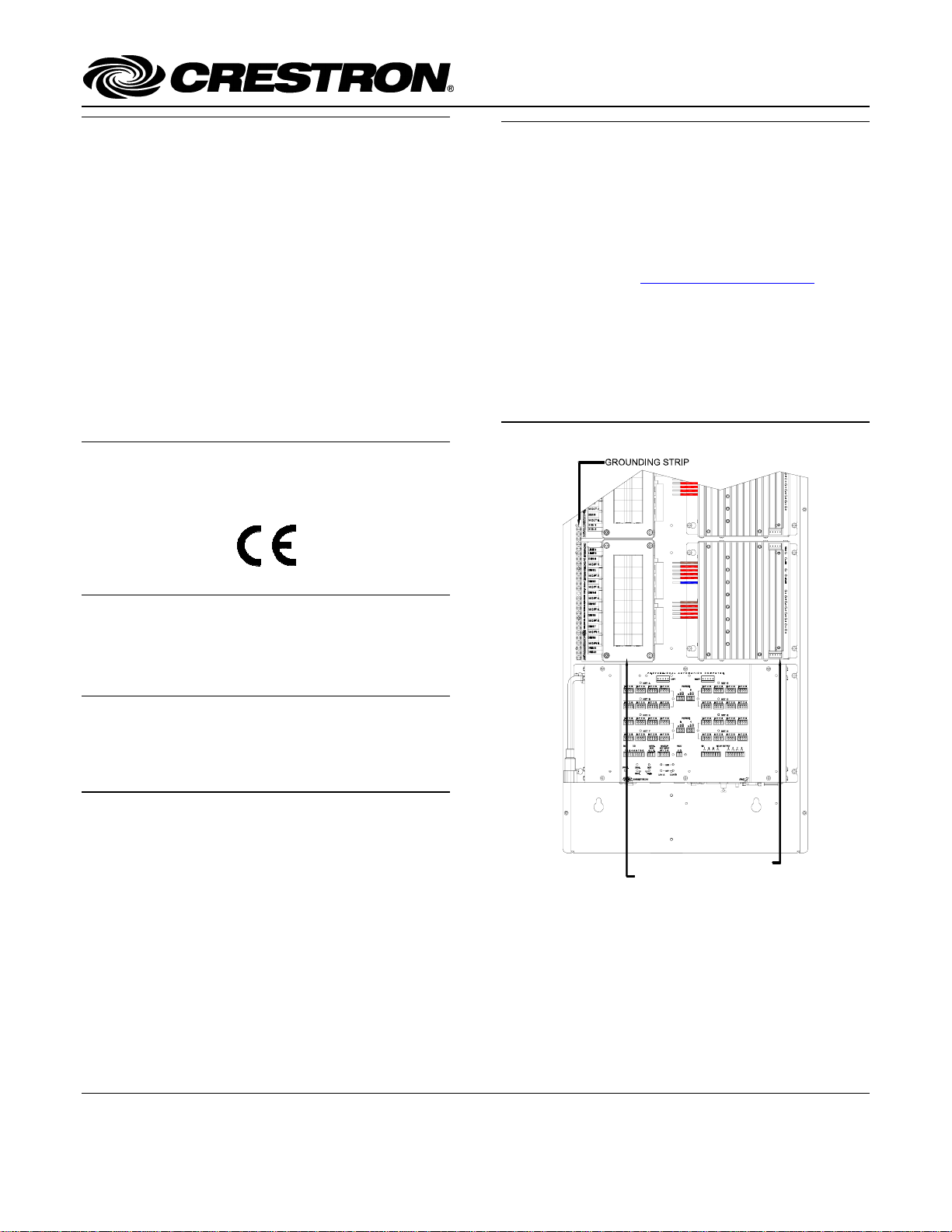
Terminal Block & Module Locations (Single-wide Enclosure)
www.crestron.com/manuals).
Installation
The terminal block and module must be mounted into a
CAENIB Enclosure by a licensed electrician, in
accordance with all national and local codes.
CAUTION: This equipment is for indoor use only and
needs to be air-cooled. Mount in a well-ventilated area.
The ambient temperature must be 0°C to 40°C (32°F to
104°F). The relative humidity must be 0% to 90% (noncondensing).
Terminal blocks are installed along the left side of singlewide enclosures and along the outside edges (left and
right sides) of double-wide enclosures. Modules are
installed along the right side of single-wide enclosures
and side-by-side in the center of double-wide enclosures.
When installing modules and terminal blocks in a doublewide enclosure, be sure to invert units on the right side so
that they can be properly wired. Refer to the illustrations
shown in the next column and next page when
considering the location of terminal blocks and modules
within an enclosure.
TERMINAL BLOCK
WIRING MODULE
Crestron Electronics, Inc. Installation Guide – DOC. 6561A
15 Volvo Drive Rockleigh, NJ 07647 (2017315)
Tel: 888.CRESTRON 04.07
Fax: 201.767.7576 Specifications subject to
www.crestron.com change without notice.
Page 2
Terminal Block with Breaker Crestron CLTIBN
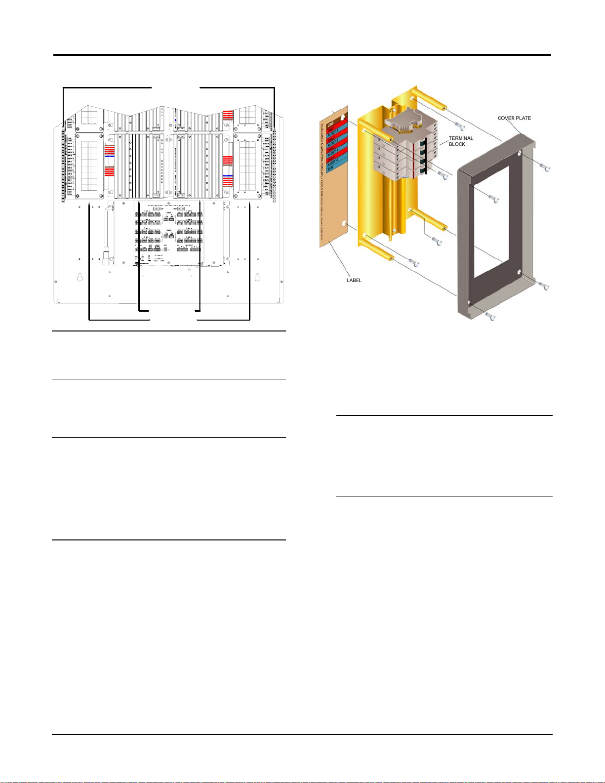
Terminal Block & Module Locations (Double-wide Enclosure)
GROUNDING STRIP
WIRING MODULES
TERMINAL BLOCKS
NOTE: Unless otherwise indicated, the lighting system
specified in this guide is modular, requiring assembly in
the field by a licensed electrician, in accordance with all
national and local codes.
Terminal Block Installation and Field Wiring
CAUTION: RISK OF ELECTRIC SHOCK—MORE
THAN ONE DISCONNECT SWITCH MAY BE
REQUIRED TO DE-ENERGIZE THE EQUIPMENT
BEFORE SERVICING.
NOTE: Both left-side and right-side adhesive wiring
labels are provided. The left-side labels are used in both
single and double-wide enclosures. The right-side labels
are only used in double-wide enclosures.
Using the diagram in the next column as reference, install
the terminal block in the CAENIB enclosure.
1. Using a Phillips screwdriver, remove the four
screws securing the cover plate to the CLTIBN
and remove the cover plate.
2. Remove the backing from the left or right
adhesive wiring label. Place the label in the
location where the CLTNIB is to be mounted on
the CAENIB. Align the holes in the label with
the appropriate holes in the CAENIB. Refer to
the latest version of the CAENIB Installation
Guide for information on mounting locations.
CLTIBN Exploded View (CLTIBN-1DELV4 Shown)
3. Use the four supplied self-tapping pan Phillips
screws (8B x ¼-inch (6 mm) length) to secure
the terminal block and the appropriate (left or
right) wiring label to the Crestron Automation
Enclosure. The wiring label lies beneath the
terminal block as shown in the terminal block-tomodule wiring diagrams on page
4.
NOTE: When installed with other terminal blocks,
CLTI-4IND and CLTI-2IND terminal blocks should
be installed at the top of a CAENIB enclosure and
grouped with other CLTI-4IND and CLTI-2IND
terminal blocks.
NOTE: Use copper conductors only – rated 75°C.
4. With the branch circuit breakers and the terminal
block circuit breakers turned off, connect the
circuit feed (LINE and NEUTRAL) and
controlled circuit (LOAD) wires to the terminal
block per the markings provided on the wiring
label (as shown in the terminal block-to-module
wiring diagrams on page
accept one 2.5 - 6.0 mm
lugs accept one conductor up to 16 mm
4). Terminal blocks
2
wire. Circuit breaker
2
. Wires
should be stripped to 12 mm. Tighten terminal
blocks to 1 Nm. Tighten circuit breaker lugs to
1.2 Nm.
5. Grounding terminal blocks are available in the
cabinet for termination of ground wires. Tighten
to 4 Nm (2.5 - 6.0 mm
5.1 Nm (16 - 25 mm
2
), 4.5 Nm (10.0 mm2), or
2
).
2 • Terminal Block: CLTIBN Installation Guide – DOC. 6561A
Page 3
Crestron CLTIBN Terminal Block with Breaker
Module Installation
CAUTION: CLXI modules contain electrostatic
sensitive devices (ESDs); units must be handled from
metal chassis – do not touch PC boards or components.
NOTE: CLXI modules are to be installed after the
enclosure has been completely wired and load wiring has
been verified. Refer to the terminal block installation
procedure on the previous page for details.
1. Use the four supplied self-tapping screws (8B x
¼ (6 mm) length) to secure the module to the
enclosure.
2. Connect the CLXI modules to their
corresponding CLTIBN terminal blocks as
shown in the terminal block-to-module wiring
diagrams that start on page
provided for installation on the right and left
sides of a CAENIB enclosure. Wires are prestripped to 12 mm. Tighten terminal blocks to
1 Nm. Tighten circuit breaker lugs to 1.2 Nm.
NOTE: Do not remove any factory-installed jumper
wires or bus-bars.
4. Illustrations are
5. Refer to the respective CLTI/CLXI Installation
Guide for instructions on completing the
installation and testing of the CLXI module.
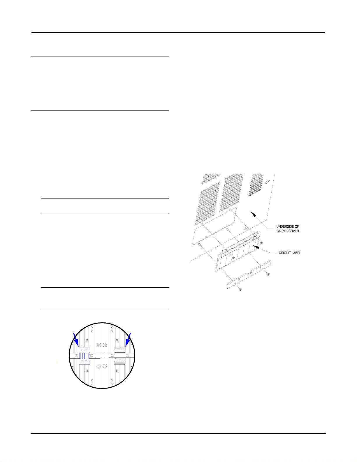
Access Door Installation
After the terminal block and module have been installed
and successfully tested, the access door must be installed
on the CAENIB’s cover in the location of the terminal
block.
1. If a blank plate is installed, remove it by
removing the nuts that secure the plate to the
CAENIB cover. Remove the plate from the
mounting studs on the CAENIB cover.
2. Install the access door assembly as shown in the
following diagram.
Install Access Door Assembly (Underside of CAENIB Cover
shown)
3. Replace the cover plate that was removed during
the terminal block installation procedure
described on the previous page.
4. If the module is being installed above or below
another module within the enclosure, attach the
supplied module interconnect cable between the
two modules. The following illustration depicts
the area within a double-wide enclosure where
the corners of four modules meet.
NOTE: One wire on the module interconnect cable
may be a different color from the rest. The color has
no bearing on its orientation during installation.
Use Module Interconnect Cable to Wire Module to Module
MODULE
INTERCONNECT
CABLE ATTACHED
CONNECTION
NOT
MADE
3. Secure the door assembly to the CAENIB cover,
by tightening the included nuts.
4. Open the access door and affix the included
blank circuit label to the door. Label the circuits
as required.
Installation Guide – DOC. 6561A Terminal Block: CLTIBN • 3
Page 4
Terminal Block with Breaker Crestron CLTIBN
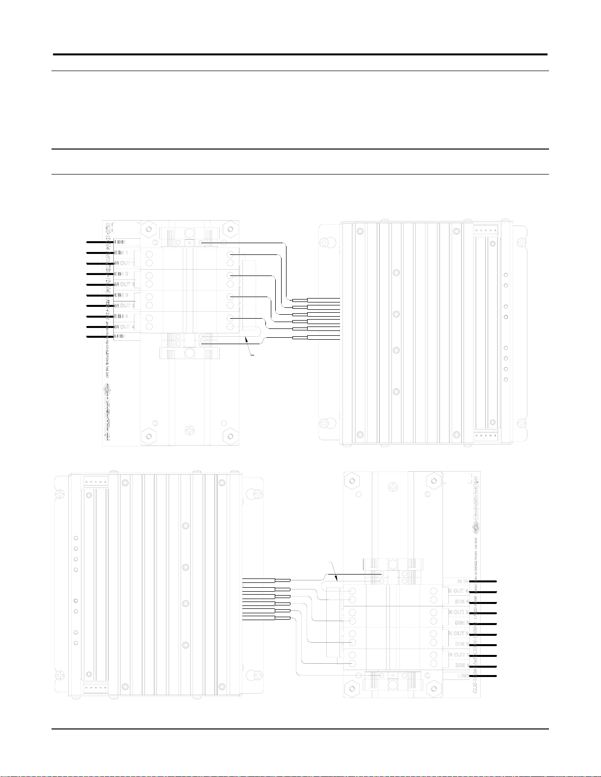
Terminal Block to Module Wiring Diagrams
With the branch circuit breakers and the terminal block circu it breakers turned off, connect the circuit feed (LINE and
NEUTRAL) and controlled circuit (LOAD) wires to the terminal blocks per the markings provided on the wiring labels (as
shown in the following diagrams). Wires should be stripped to 12 mm. Terminal blocks accept one 2.5 - 6.0 mm
should be tightened to 1 Nm. Circuit breaker lugs accept up to one 16 mm
2
wire and should be tightened to 1.2 Nm.
NOTE: Illustrations are provided for installation on the right and left sides of a CAENIB enclosure. Illustrations show the
terminal block with the cover plate removed.
CLTIBN-1DIM4 to CLXI-1DIM4
Wiring of CLTIBN-1DIM4 Terminal Block and CLXI-1DIM4 (Single-wide and Left Side Double-wide Enclosures)
LINE
TO LOAD 1
TO LOAD 1
TO LOAD 2
TO LOAD 2
TO LOAD 3
TO LOAD 3
TO LOAD 4
TO LOAD 4
NEUTRAL
BROWN
RED
RED
RED
RED
BLUE
2
wire and
FACTORY INSTALLED
JUMPER WIRE
DO NOT REMOVE
Wiring of CLTIBN-1DIM4 Terminal Block and CLXI-1DIM4 (Right Side Double-wide Enclosures)
FACTORY INSTALLED
JUMPER WIRE
DO NOT REMOVE
BLUE
RED
RED
RED
RED
BROWN
NEUTRAL
TO LOAD 4
TO LOAD 4
TO LOAD 3
TO LOAD 3
TO LOAD 2
TO LOAD 2
TO LOAD 1
TO LOAD 1
LINE
4 • Terminal Block: CLTIBN Installation Guide – DOC. 6561A
Page 5

Crestron CLTIBN Terminal Block with Breaker
CLTIBN-2DIM8 to CLXI-2DIM8
Wiring of CLTIBN-2DIM8 Terminal Block and CLXI-2DIM8 (Single-wide and Left Side Double-wide Enclosures)
LINE 1
LINE 2
TO LOAD 1
TO LOAD 1
TO LOAD 2
TO LOAD 2
TO LOAD 3
TO LOAD 3
TO LOAD 4
TO LOAD 4
TO LOAD 5
TO LOAD 5
TO LOAD 6
TO LOAD 6
TO LOAD 7
TO LOAD 7
TO LOAD 8
TO LOAD 8
NEUTRAL 1
NEUTRAL 2
FACTORY INSTALLED
JUMPER WIRES
DO NOT REMOVE
BROWN
RED
RED
RED
RED
BLUE
BROWN
RED
RED
RED
RED
NOTE: The blue wire from the module will share a circuit breaker lug with the neutral bus bar.
Wiring of CLTIBN-2DIM8 Terminal Block and CLXI-2DIM8 (Right Side Double-wide Enclosures)
FACTORY INSTALLED
JUMPER WIRES
DO NOT REMOVE
RED
RED
RED
RED
BROWN
BLUE
RED
RED
RED
RED
BROWN
NOTE: The blue wire from the module will share a circuit breaker lug with the neutral bus bar.
NEUTRAL 2
NEUTRAL 1
TO LOAD 8
TO LOAD 8
TO LOAD 7
TO LOAD 7
TO LOAD 6
TO LOAD 6
TO LOAD 5
TO LOAD 5
TO LOAD 4
TO LOAD 4
TO LOAD 3
TO LOAD 3
TO LOAD 2
TO LOAD 2
TO LOAD 1
TO LOAD 1
LINE 2
LINE 1
Installation Guide – DOC. 6561A Terminal Block: CLTIBN • 5
Page 6

Terminal Block with Breaker Crestron CLTIBN
CLTIBN-1DELV4 to CLXI-1DELV4
Wiring of CLTIBN-1DELV4 Terminal Block and CLXI-1DELV4 (Single-wide and Left Side Double-wide Enclosures)
LINE
TO LOAD 1
TO LOAD 1
TO LOAD 2
TO LOAD 2
TO LOAD 3
TO LOAD 3
TO LOAD 4
TO LOAD 4
NEUTRAL
FACTORY INSTALLED
JUMPER WIRE
DO NOT REMOVE
BROWN
RED
RED
RED
RED
BLUE
Wiring of CLTIBN-1DELV4 Terminal Block and CLXI-1DELV4 (Right Side Double-wide Enclosures)
FACTORY INSTALLED
JUMPER WIRES
DO NOT REMOVE
BLUE
RED
RED
RED
RED
BROWN
NEUTRAL
TO LOAD 4
TO LOAD 4
TO LOAD 3
TO LOAD 3
TO LOAD 2
TO LOAD 2
TO LOAD 1
TO LOAD 1
LINE
6 • Terminal Block: CLTIBN Installation Guide – DOC. 6561A
Page 7

Crestron CLTIBN Terminal Block with Breaker
CLTIBN-1MC4 to CLXI-1MC4
Wiring of CLTIBN-1MC4 Terminal Block and CLXI-1MC4 (Single-wide and Left Side Double-wide Enclosures)
LINE
TO MOTOR 1
BROWN
RED
TO MOTOR 2
TO MOTOR 3
TO MOTOR 4
NEUTRAL
FACTORY INSTALLED
JUMPER WIRES
DO NOT REMOVE
Wiring of CLTIBN-1MC4 Terminal Block and CLXI-1MC4 (Right Side Double-wide Enclosures)
FACTORY INSTALLED
JUMPER WIRES
DO NOT REMOVE
YELLOW
RED
YELLOW
RED
YELLOW
RED
YELLOW
BLUE
NEUTRAL
BLUE
YELLOW
RED
YELLOW
RED
YELLOW
RED
YELLOW
RED
BROWN
TO MOTOR 4
TO MOTOR 3
TO MOTOR 2
TO MOTOR 1
LINE
Installation Guide – DOC. 6561A Terminal Block: CLTIBN • 7
Page 8

Terminal Block with Breaker Crestron CLTIBN
CLTIBN-2DIM2 to CLXI-2DIM2
Wiring of CLTIBN-2DIM2 Terminal Block and CLXI-2DIM2 (Single-wide and Left Side Double-wide Enclosures)
LINE 1
LINE 2
TO LOAD 1
TO LOAD 1
TO LOAD 2
TO LOAD 2
NEUTRAL 1
NEUTRAL 2
FACTORY INSTALLED
JUMPER WIRES
DO NOT REMOVE
BROWN
RED
BLUE
BROWN
RED
Wiring of CLTIBN-2DIM2 Terminal Block and CLXI-2DIM2 (Right Side Double-wide Enclosures)
FACTORY INSTALLED
JUMPER WIRES
DO NOT REMOVE
RED
BROWN
BLUE
RED
BROWN
NEUTRAL 2
NEUTRAL 1
TO LOAD 2
TO LOAD 2
TO LOAD 1
TO LOAD 1
LINE 2
LINE 1
8 • Terminal Block: CLTIBN Installation Guide – DOC. 6561A
Page 9

Crestron CLTIBN Terminal Block with Breaker
CLTIBN-2IND to CLXI-2IND
NOTE: The CLTIBN-2IND inputs connect to the DIM OUT and N OUT lines of a CLTI dimming terminal block.
Wiring of CLTIBN-2IND Terminal Block and CLXI-2IND (Single-wide and Left Side Double-wide Enclosures)
FROM DIMMER 1
TO LOAD 1
TO LOAD 1
TO LOAD 2
TO LOAD 2
FROM DIMMER 1
FACTORY INSTALLED
JUMPER WIRES
DO NOT REMOVE
BLUE
BLUE
BLUE
BLUE
Wiring of CLTIBN-2IND Terminal Block and CLXI-2IND (Right Side Double-wide Enclosures)
FACTORY INSTALLED
JUMPER WIRES
BLUE
BLUE
DO NOT REMOVE
FROM DIMMER 2
FROM DIMMER 1
BLUE
BLUE
TO LOAD 2
TO LOAD 2
TO LOAD 1
TO LOAD 1
FROM DIMMER 2
FROM DIMMER 1
Installation Guide – DOC. 6561A Terminal Block: CLTIBN • 9
Page 10

Terminal Block with Breaker Crestron CLTIBN
CLTIBN-4HSW4 to CLXI-4HSW4
Wiring of CLTIBN-4HSW4 Terminal Block and CLXI-4HSW4 (Single-wide and Left Side Double-wide Enclosures)
LINE 1
LINE 2
LINE 3
LINE 4
TO LOAD 1
TO LOAD 2
TO LOAD 3
TO LOAD 4
BROWN
BLUE
RED
BROWN
RED
BROWN
RED
NEUTRAL 1
NEUTRAL 2
NEUTRAL 3
NEUTRAL 4
FACTORY INSTALLED
JUMPER WIRES
DO NOT REMOVE
BROWN
RED
Wiring of CLTIBN-4HSW4 Terminal Block and CLXI-4HSW4 (Right Side Double-wide Enclosures)
FACTORY INSTALLED
JUMPER WIRES
DO NOT REMOVE
RED
BROWN
RED
BROWN
RED
BROWN
RED
BLUE
BROWN
NEUTRAL 4
NEUTRAL 3
NEUTRAL 2
NEUTRAL 1
TO LOAD 4
TO LOAD 3
TO LOAD 2
TO LOAD 1
LINE 4
LINE 3
LINE 2
LINE 1
10 • Terminal Block: CLTIBN Installation Guide – DOC. 6561A
Page 11

Crestron CLTIBN Terminal Block with Breaker
CLTIBN-4IND to CLXI-4IND
NOTE: The CLTIBN-4IND inputs connect to the DIM OUT and N OUT lines of a CLTI dimming terminal block.
Wiring of CLTIBN-4IND Terminal Block and CLXI-4IND (Single-wide and Left Side Double-wide Enclosures)
FROM DIMMER 1
FROM DIMMER 2
FROM DIMMER 3
FROM DIMMER 4
TO LOAD 1
TO LOAD 1
TO LOAD 2
TO LOAD 2
TO LOAD 3
TO LOAD 3
TO LOAD 4
TO LOAD 4
FROM DIMMER 1
FROM DIMMER 2
FROM DIMMER 3
FROM DIMMER 4
FACTORY INSTALLED
JUMPER WIRES
DO NOT REMOVE
BLUE
BLUE
BLUE
BLUE
BLUE
BLUE
BLUE
BLUE
Wiring of CLTIBN-4IND Terminal Block and CLXI-4IND (Right Side Double-wide Enclosures)
FACTORY INSTALLED
JUMPER WIRES
BLUE
BLUE
DO NOT REMOVE
BLUE
BLUE
BLUE
BLUE
BLUE
BLUE
FROM DIMMER 4
FROM DIMMER 3
FROM DIMMER 2
FROM DIMMER 1
TO LOAD 4
TO LOAD 4
TO LOAD 3
TO LOAD 3
TO LOAD 2
TO LOAD 2
TO LOAD 1
TO LOAD 1
FROM DIMMER 4
FROM DIMMER 3
FROM DIMMER 2
FROM DIMMER 1
Installation Guide – DOC. 6561A Terminal Block: CLTIBN • 11
Page 12

Terminal Block with Breaker Crestron CLTIBN
Return and Warranty Policies
Further Inquiries
If you cannot locate specific information or have
questions after reviewing this guide, please t a ke
advantage of Crestron's award winning customer service
team by calling the Crestron corporate headquarters at
1-888-CRESTRON [1-888-273-7876]. For assistance in
your local time zone, refer to the Crestron website
http://www.crestron.com/offices) for a listing of Crestron
(
worldwide offices.
You can also log onto the online help section of the
Crestron website (
ask questions about Crestron products. First-time users
will need to establish a user account to fully benefit from
all available features.
http://www.crestron.com/onlinehelp) to
Merchandise Returns / Repair Service
1. No merchandise may be returned for credit, exchange or service
without prior authorization from CRESTRON. To obtain
warranty service for CRESTRON products, contact an authorized
CRESTRON dealer. Only authorized CRESTRON dealers may
contact the factory and request an RMA (Return Merchandise
Authorization) number. Enclose a note specifying the nature of
the problem, name and phone number of contact person, RMA
number and return address.
2. Products may be returned for credit, exchange or service with a
CRESTRON Return Merchandise Authorization (RMA) number.
Authorized returns must be shipped freight prepaid to
CRESTRON, 6 Volvo Drive, Rockleigh, N.J. or its authorized
subsidiaries, with RMA number clearly marked on the outside of
all cartons. Shipments arriving freight collect or without an RMA
number shall be subject to refusal. CRESTRON reserves the right
in its sole and absolute discretion to charge a 15% restocking fee
plus shipping costs on any products returned with an RMA.
3. Return freight charges following repair of items under warranty
shall be paid by CRESTRON, shipping by standard ground
carrier. In the event repairs are found to be non-warranty, return
freight costs shall be paid by the purchaser.
CRESTRON Limited Warranty
CRESTRON ELECTRONICS, Inc. warrants its products to be free from
manufacturing defects in materials and workmanship under normal use
for a period of three (3) years from the date of purchase from
CRESTRON, with the following exceptions: disk drives and any other
moving or rotating mechanical parts, pan/tilt heads and power supplies
are covered for a period of one (1) year; touchscreen display and overlay
components are covered for 90 days; batteries and incandescent lamps
are not covered.
This warranty extends to products purchased directly from CRESTRON
or an authorized CRESTRON dealer. Purchasers should inquire of the
dealer regarding the nature and extent of the dealer's warranty, if any.
CRESTRON shall not be liable to honor the terms of this warranty if the
product has been used in any application other than that for which it was
intended or if it has been subjected to misuse, accidental damage,
modification or improper installation procedures. Furthermore, this
warranty does not cover any product that has had the serial number
altered, defaced or removed.
This warranty shall be the sole and exclusive remedy to the original
purchaser. In no event shall CRESTRON be liable for incidental or
consequential damages of any kind (property or economic damages
inclusive) arising from the sale or use of this equipment. CRESTRON is
not liable for any claim made by a third party or made by the purchaser
for a third party.
CRESTRON shall, at its option, repair or replace any product found
defective, without charge for parts or labor. Repaired or replaced
equipment and parts supplied under this warranty shall be covered only
by the unexpired portion of the warranty.
Except as expressly set forth in this warranty, CRESTRON makes no
other warranties, expressed or implied, nor authorizes any other party to
offer any warranty, including any implied warranties of merchantability
or fitness for a particular purpose. Any implied warranties that may be
imposed by law are limited to the terms of this limited warranty. This
warranty statement supersedes all previous warranties.
Trademark Information
All brand names, product names, and trademarks are the sole property of their respective
owners. Windows is a registered trademark of Microsoft Corporation.
Windows95/98/Me/XP/Vista and WindowsNT/2000 are trademarks of Microsoft Corporation.
12 • Terminal Block: CLTIBN Installation Guide – DOC. 6561A
 Loading...