

Page 1

Crestron C2VEQ-4
Volume/Equalizer Control Expansion Card
Operations & Installation Guide
Page 2

This document was prepared and written by the Technical Documentation department at:
Crestron Electronics, Inc.
15 Volvo Drive
Rockleigh, NJ 07647
1-888-CRESTRON
All brand names, product names and trademarks are the property of their respective owners.
©2003 Crestron Electronics, Inc.
Page 3

Crestron C2VEQ-4 Volume/Equalizer Control Expansion Card
Contents
Volume/Equalizer Control Expansion Card: C2VEQ-4 1
Introduction ...............................................................................................................................1
Features and Functions................................................................................................ 1
Specifications ..............................................................................................................3
Physical Description.................................................................................................... 3
Industry Compliance ...................................................................................................5
Installation and Hookup............................................................................................................. 5
Installation................................................................................................................... 5
Hookup........................................................................................................................ 6
Programming Software.............................................................................................................. 7
Digital Audio Tools..................................................................................................... 7
Programming with SIMPL Windows.......................................................................... 8
Problem Solving ......................................................................................................................19
Troubleshooting ........................................................................................................19
Further Inquiries........................................................................................................ 19
Future Updates ..........................................................................................................19
Return and Warranty Policies.................................................................................................. 20
Merchandise Returns / Repair Service ...................................................................... 20
CRESTRON Limited Warranty ................................................................................20
Operations & Installation Guide - DOC. 6136 Contents • i
Page 4

Page 5

Crestron C2VEQ-4 Volume/Equalizer Control Expansion Card
Volume/Equalizer Control Expansion Card: C2VEQ-4
Introduction
Features and Functions
The Crestron® C2VEQ-4 Volume/Equalizer Control expansion card is a digitally
controlled 4-channel audio processor that provides volume/tone, mixer and
equalization capabilities for the Crestron PRO2, PAC2, RACK2, or AV2 (with card
cage) 2-Series control systems. The C2VEQ-4 fits in any of the 2-Series control
system’s 40 Mb/s high-speed communications Y-bus slots.
Each channel of the C2VEQ-4 has independent settings for volume, treble, bass,
mute, and mixer controls plus a 12-band parametric equalizer.
Functional Summary
• Four balanced/unbalanced audio I/O channels
• 24-bit 96KHz A/D and D/A converters with dual DSPs provide improved
audio quality
• Independent settings for volume, treble, bass, and mute per channel
• 4 x 4 matrix mixer controls set the percentage of each input desired at each
output
• Five modes of audio equalization per channel
- a ten-band graphic equalizer and two-band parametric equalizer
- a five-band graphic equalizer and seven-band parametric equalizer
- a speech-optimized five-band graphic equalizer and seven-band
parametric equalizer
- a three-band graphic equalizer and nine-band parametric equalizer
- a full twelve-band parametric equalizer
Volume, bass, and treble ramp times, scaling, preset levels, and volume muting may
be specified on a per-channel basis. All of these aspects are software controllable.
Volume, bass, and treble control may be sent to more than one channel via software
to support stereo applications.
Input and output connections are completely independent of each other. Therefore, it
is possible to have a balanced input paired with an unbalanced output and vice-versa.
Operations & Installation Guide - DOC. 6136 Volume/Equalizer Control Expansion Card: C2VEQ-4 • 1
Page 6
Volume/Equalizer Control Expansion Card Crestron C2VEQ-4
The treble and bass controls are independent from volume and are individually
controlled for each channel. Each channel includes a muting relay. When the signal
driving Mute1 goes high, the muting circuit is activated providing <-100dBV output
level from any volume level. Likewise, channels “2,” “3,”and “4” drive Mute2,
Mute3, and Mute4, respectively. When the muting signal goes low, the muting
circuit is deactivated and the volume and tone return to their original preset levels.
NOTE: MuteAll is an override. All channels are muted when this signal is high.
When it is low, the channels follow the state of Mute1, Mute2, Mute3, and Mute4.
Each of the four channels has a twelve-filter parametric equalizer that permits you to
correct for acoustical distortions in the listening area or in the speakers themselves,
and/or to establish preset values that enhance the sound conditions for favorite music
or recording media.
The 12 filters are identical in function. Each delivers up to 12dB of boost or cut
when using DAT software; from -36dB to +24dB in a SIMPL program. Each filter
also has an adjustable bandwidth control (from .02 octaves to 2 octaves), and a
center frequency control range from 10 Hz to 20 KHz. Use each filter anywhere in
the audio spectrum, not just pre-selected ranges as typically found on graphic
equalizers. In addition, you can select from among five filter types (low pass, high
pass, EQ filter, bass shelf, and treble shelf) or select no filter.
Each channel is equipped with protective relays that turn ON only after safe
conditions are sustained by the electronic circuitry. This feature protects the output
from “pops” caused by accidental power-down/power-up conditions to the
C2VEQ-4.
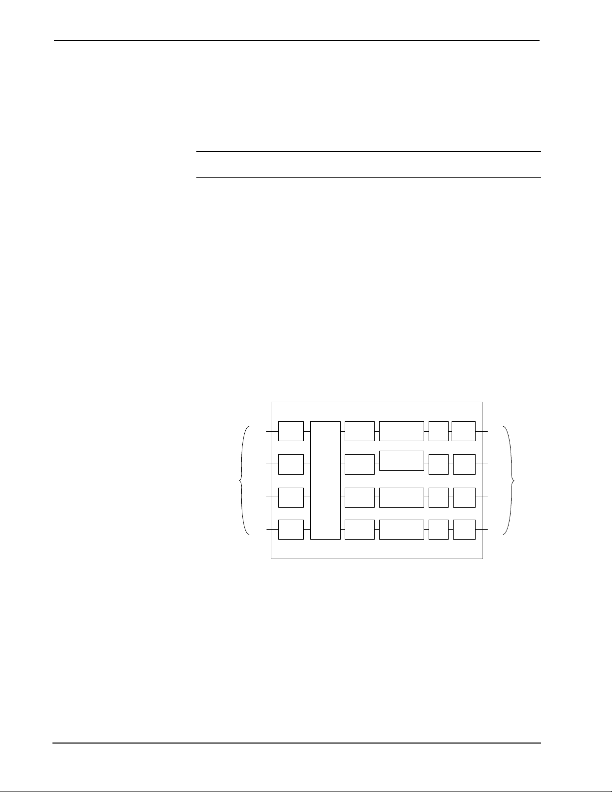
C2VEQ-4 Simplified Block Diagram
Line-Level
Audio Input
(Balanced or
Unbalanced)
Ch 1
Ch 2
Ch 3
Ch 4
A/D
A/D
A/D
A/D
4 Input
X
4 Output
Mixer
12 Band
Eq
12 Band
Eq
12 Band
Eq
12 Band
Eq
Volume &
Tone Control
Volume &
Tone Control
Volume &
Tone Control
Volume &
Tone Control
D/A
D/A
D/A
D/A
Mute
Relay
Mute
Relay
Mute
Relay
Mute
Relay
Ch 1
Ch 2
Ch 3
Ch 4
Line-Level
Audio Output
(Balanced or
Unbalanced)
2 • Volume/Equalizer Control Expansion Card: C2VEQ-4 Operations & Installation Guide - DOC. 6136
Page 7
Crestron C2VEQ-4 Volume/Equalizer Control Expansion Card
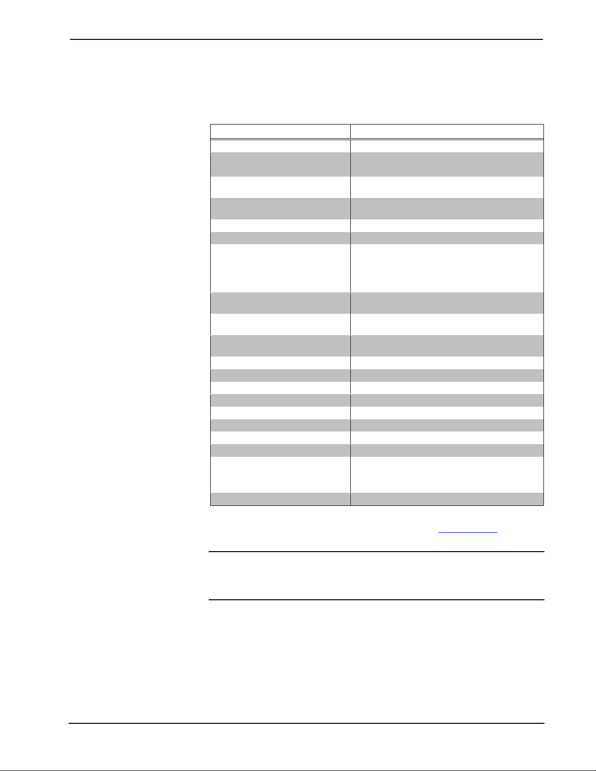
Specifications
The following table provides specifications for the C2VEQ-4.
C2VEQ-4 Specifications
SPECIFICATION DETAILS
Power Requirements 8.0 Watts
Control System Update Files
2-Series Control System Update File Version 3.083.CUZ or later
Input Channels (labeled 1 – 4) Two 5-pin mini-connectors: two channels plus ground
Output Channels (labeled 1 – 4) Two 5-pin mini-connectors: two channels plus ground
Volume (per channel) -80dB to +20dB, 0.5dB control step [balanced I/O]
Mute (per channel) > -100dB
Tone (per channel) Bass gain range ±15dB
Frequency response ±0.1dB 20-22kHz
Total harmonic distortion (THD)
+ Noise
S/N ratio >97dB balanced, >95dB unbalanced,
Crosstalk > -90dB 20Hz-22kHz
Common mode rejection > 90dB 20Hz-22kHz
Input level (max.) 4Vrms balanced, 2Vrms single-ended
Input impedance 10K ohms balanced, 5K ohm single ended
Output level 4Vrms balanced, 2Vrms single-ended
Output impedance 200 ohms balanced, 100 ohms single-ended
Environmental temperature 32° to 122°F (0° to 50°C)
Humidity 10% to 90% RH (non-condensing)
Dimensions Height: 0.98 in (2.49 cm)
Weight 3.75 oz (0.105 kg)
1 Crestron 2-Series control systems include the AV2 with CAGE2, PAC2, PRO2, and RACK2.
2 Filenames for 2-Series control system update files have a CUZ extension and can be obtained from
the Downloads | Software Updates section of the Crestron website (www.crestron.com
note after this footnote.
1, 2
per connector.
per connector.
Bass step size 0.5dB
Treble gain range ±15dB
Treble step size 0.5dB
±0.5dB 10Hz-30kHz
<0.008% @1kHz
20 to 22kHz A-weighted
20 to 22kHz A-weighted
Width: 5.00 in (12.70 cm)
Depth: 6.77 in (17.20 cm)
). Refer to
NOTE: Crestron software and any files on the website are for Authorized Crestron
dealers and Crestron Authorized Independent Programmers (CAIP) only. New users
may be required to register to obtain access to certain areas of the site (including the
FTP site).
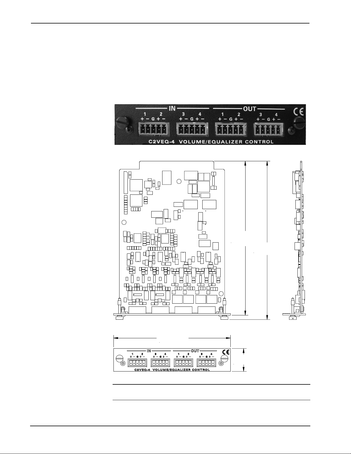
Physical Description
The C2VEQ-4 is a circuit board fastened to an aluminum faceplate. The card is
manufactured to easily fit in an unoccupied Y-bus slot of a Crestron 2-Series control
system.
Operations & Installation Guide - DOC. 6136 Volume/Equalizer Control Expansion Card: C2VEQ-4 • 3
Page 8
Volume/Equalizer Control Expansion Card Crestron C2VEQ-4
Four mini connectors provide the interface to four channels of balanced/unbalanced
audio input (IN 1-4) and four channels of balanced/unbalanced audio output (OUT
1-4). Connect the balanced/unbalanced input (IN) ports to the audio output of any
A/V equipment that needs volume, treble, bass, mixer, and/or equalization control;
connect the balanced/unbalanced output (OUT) ports to an amplifier. Each channel
includes a muting relay.
Refer to the following illustrations for a detailed view.
C2VEQ-4 Faceplate
C2VEQ-4: Top, Side & Front Views
6.59 in.
(16.73 cm)
6.77 in.
(17.20 cm)
5.00 in.
(12.70 cm)
0.98 in
(2.49 cm)
NOTE: These diagrams are for illustration purposes only and do not show the exact
location of components on the circuit board.
4 • Volume/Equalizer Control Expansion Card: C2VEQ-4 Operations & Installation Guide - DOC. 6136
Page 9

Crestron C2VEQ-4 Volume/Equalizer Control Expansion Card
Industry Compliance
As of the date of manufacture, the C2VEQ-4 has been tested and found to comply
with specifications for CE marking and standards per EMC and
Radiocommunications Compliance Labelling (N11785).
NOTE: This device complies with part 15 of the FCC rules. Operation is subject to
the following two conditions: (1) this device may not cause harmful interference,
and (2) this device must accept any interference received, including interference that
may cause undesired operation.
Installation and Hookup
The C2VEQ-4 cards are designed for installation into a dedicated expansion slot on
a 2-Series control system.
The only tools required for installation are a Phillips screwdriver, a grounding strap,
and a grounded workstation.
CAUTION: The C2VEQ-4 and control system contain electro-static discharge
(ESD) sensitive devices. Perform the following procedure while wearing a
grounding strap that is properly grounded and on a grounded workstation to avoid
damaging the C2VEQ-4 and/or the control system.
CAUTION: To prevent stripping of screw heads, threads, or mounting holes, DO
NOT over tighten screws. Tighten only to the specification listed in the individual
step(s).
NOTE: If the C2VEQ-4 is being installed in an AV2, the optional CAGE2 must be
installed before continuing below. For instructions on installing the CAGE2 into an
AV2 control system, refer to the latest revision of the CAGE2 3-Card Expansion
Cage for AV2 Installation Guide (Doc. 5964).
Installation
Follow the instructions below to install the C2VEQ-4 into a 2-Series control system.
1. Disconnect power from the control system.
2. Remove the two screws and blank faceplate from the desired slot in the
control system using a Phillips screwdriver.
3. Align the C2VEQ-4 with the card guides in the open slot and slide the
expansion card into the slot.
4. Firmly press both ends of the C2VEQ-4 faceplate to seat the expansion
card in the control system connector.
5. Hand-tighten the thumbscrews to secure the C2VEQ-4 in position.
6. Reapply power to the control system.
Operations & Installation Guide - DOC. 6136 Volume/Equalizer Control Expansion Card: C2VEQ-4 • 5
Page 10

Volume/Equalizer Control Expansion Card Crestron C2VEQ-4
Hookup
Four balanced/unbalanced inputs are provided for audio input, utilizing five-position
mini-connectors. Audio inputs may be balanced using (+) and (-) inputs, or
unbalanced using (+) input for signal and connecting (-) input to (G) and signal
source ground.
Four balanced/unbalanced outputs are provided, also utilizing five-position miniconnectors.
NOTE: An unbalanced input may use a balanced or unbalanced output. Likewise, a
balanced input may use a balanced or unbalanced output.
For connection details, refer to the following diagrams.
Typical Balanced/Unbalanced Inputs and Outputs
INPUTS OUTPUTS
NOTE: Using the unbalanced configuration for the audio output reduces the total
audio gain by 6dB.
6 • Volume/Equalizer Control Expansion Card: C2VEQ-4 Operations & Installation Guide - DOC. 6136
Page 11

Crestron C2VEQ-4 Volume/Equalizer Control Expansion Card
p
b
Programming Software
Have a comment about
Crestron software?
Direct software related
suggestions and/or
complaints to Crestron via
email
(software@crestron.com)
Do not forward any queries
to this address. Instead refer
to “Further Inquiries” on
age 19 for assistance.
.
Setup is easy thanks to Crestron’s Windows
following are recommended software version requirements for the PC:
• SIMPL Windows version 2.04.14 or later with library update file 240.
Requires SIMPL+ Cross Compiler version 1.1.
• Crestron Database version 15.8.8 or later. Required by SIMPL Windows.
• Digital Audio Tools version 1.03.00 or later.
The Digital Audio Tools software is the preferred method to adjust equalization. In
fact, if you want to use a graphic equalizer, you MUST use Digital Audio Tools,
ecause this is where the default graphic equalizer characteristics are set up. Refer to
the following section for more details on using Digital Audio Tools.
-based programming software. The
Digital Audio Tools
The full parametric equalization controls built into the C2VEQ-4 provide graphic
and parametric equalization, programmable using Crestron's Digital Audio Tools
software or SIMPL Windows. The Digital Audio Tools (DAT) software is free and
available from the download section of the Crestron website (www.crestron.com
Almost all users will use the Digital Audio Tools and not the SIMPL Windows
symbol to adjust equalization because of the program’s simplicity, speed, and ease of
operation. From the point of view of the symbols for the C2VEQ-4, all equalization
is parametric; graphic equalizers are just parametric equalizers with specific default
frequencies, Q (bandwidth), and type. If you want to use a graphic equalizer, you
MUST use Digital Audio Tools, because this is where the default graphic equalizer
characteristics are set up. SIMPL Windows programmers might want to set up
sliders from the TrimBand gains to let the user modify slightly what the programmer
has stored.
).
The C2VEQ-4 adjustments in Digital Audio Tools contain five tabs:
• Master Volume – for setting the overall volume in the four channels.
• Mixer – for setting the level of each of the four possible inputs you want to
appear at each channel output, plus setting the relative gain of each channel.
You can also specify up to five presets of various setting combinations.
Using these adjustments properly lets you compensate for analog sources
with different input levels to obtain a seamless transition between sources at
a given volume level.
• Graphic EQ – for choosing the number of graphic equalizers, and provides
access to the graphic equalizer sliders.
• Parametric EQ – for making parametric equalization adjustments and
permits setting up to five equalization filter presets per output channel.
• Communications – for setting up communications and adjusting the
equalizer in real time.
For additional details, refer to the Digital Audio Tools help file.
Operations & Installation Guide - DOC. 6136 Volume/Equalizer Control Expansion Card: C2VEQ-4 • 7
Page 12

Volume/Equalizer Control Expansion Card Crestron C2VEQ-4
Programming with SIMPL Windows
NOTE: The following assumes that the reader has knowledge of SIMPL Windows.
If not, refer to the extensive help information provided with the software.
NOTE: The following are acceptable file extensions for programs that include a
C2VEQ-4, developed for specific control system types:
.smw projectname.smw (source file)
.spz projectname.spz (compiled file for 2-series)
.usp projectname.usp (source code module for SIMPL+)
NOTE: In the following, the PRO2 control system is used.
SIMPL Windows is Crestron's primary software for programming Crestron control
systems. It provides a well-designed graphical environment with a number of
workspaces (i.e., windows) in which a programmer can select, configure, program,
test, and monitor a Crestron control system. SIMPL Windows offers drag and drop
functionality in a familiar Windows
This section describes a sample SIMPL Windows program that includes a
C2VEQ-4.
environment.
Configuration Manager is where programmers “build” a Crestron control system by
selecting hardware from the Device Library. In Configuration Manager, drag the
PRO2 from the Control Systems folder of the Device Library and drop it in the
upper pane of the System Views. The PRO2 with its associated ports is displayed in
the System Views upper pane.
PRO2 System View
The System Views lower pane displays the PRO2 system tree. This tree can be
expanded to display and configure the ports.
Expanded PRO2 System Tree
C2Y Card Slot in Configuration Manager
To incorporate a C2VEQ-4 card into the system, drag the C2VEQ-4 from the Plug-in
Control Cards | Cards (2-Series Y Bus) folder of the Device Library and drop it on
8 • Volume/Equalizer Control Expansion Card: C2VEQ-4 Operations & Installation Guide - DOC. 6136
Page 13

Crestron C2VEQ-4 Volume/Equalizer Control Expansion Card
E
C2Y Card Slot (01) in System Views. The PRO2 displays the C2VEQ-4 in slot 01.
Click + to expand the tree so you can view the ports of the
following graphic.
Expanded Slot 1:C2COM-3
C2VEQ-4. Refer to
xample Program
C2VEQ-4 Symbols in Programming Manager
Programming Manager is where programmers “program” a Crestron control system
by assigning signals to symbols. Due to the extensive functionality of the C2VEQ-4,
a single symbol in SIMPL Windows would be too complex. Instead, the C2VEQ-4 is
broken up into slots. In Program Manager, expand the C2VEQ-4 to view the
individual slots, and then drag the desired symbol to Detail View. The slots and
corresponding symbols are described beginning on page 10.
NOTE: At power on, volume is set to zero; bass and treble are flat; and the mixers
are set to route 100% of each input only to the corresponding output. Changes to the
volume, bass, treble, and mixer settings are provided by the SIMPL program. EQ
trim and filter control presets are stored in the card itself, and can be activated using
“recall” functions. EQ, trim and mixer presets, if any, are stored and can be activated
using recall functions
NOTE: Before attempting to program the equalization controls in SIMPL Windows,
please study the example program. There are some subtleties that must be carefully
handled. For example, if you intend to directly set one of the <TrimBandOut>
signals in your program, and the <TrimBandOut_FB> signal can be set to a
different value by some other method (using DAT software or recalling presets), do
not connect the <TrimBandOut_FB> signal back to the <TrimBandOut>.
Oscillations might result between the directly driven value and the different
feedback value. Instead, use an Analog Increment with Optional Feedback symbol.
(Refer to “New Symbols” on page 18 for more details.) Connect the directly driven
value and the <TrimBandOut_FB> signal to individual inputs. Connect its output
to the <TrimBandOut> input of the C2VEQ-4. The same logic applies to any value
that can be changed in two places. Refer to the example program.
An example program for the C2VEQ-4 is available from the Crestron FTP site
(ftp://ftp.crestron.com/Examples
Operations & Installation Guide - DOC. 6136 Volume/Equalizer Control Expansion Card: C2VEQ-4 • 9
). Search for C2VEQ-4.Basic Example.zip.
Page 14

Volume/Equalizer Control Expansion Card Crestron C2VEQ-4
General Audio Controls – Slot 1, SubSlot 1
Refer to the table that follows the symbol for a list of inputs and their functional
descriptions.
General Audio Controls Symbol
The C2VEQ-4 symbol is defined by the assigned inputs. The diagram above shows
the C2VEQ-4 symbol in SIMPL Windows.
C2VEQ-4 General Audio Controls Symbol Input Descriptions
Signal
Name Value Definition
Type
Digital MuteOut (1 through 4)
plus MuteAll
Analog
VolOut (1 through 4) 0 to 100%
TrebOut (1 through 4) 0 to 100%
BassOut (1 through 4) 0 to 100%
1/0 High = Mute On
Low = Mute Off
0% = Volume set to lowest
-80dB to +20dB
± 15dB
± 15dB
100% = Volume set to
highest
50%=Flat Treble
0%= -15dB
100%= +15dB
50%=Flat Bass
0%= -15dB
100%= +15dB
10 • Volume/Equalizer Control Expansion Card: C2VEQ-4 Operations & Installation Guide - DOC. 6136
Page 15

Crestron C2VEQ-4 Volume/Equalizer Control Expansion Card
Mixer Controls – Slot 1, SubSlot 2
The 4x4 matrix mixer controls provide the equivalent of a small-scale mixing board.
These controls use a logarithmic scale (0dB to –80dB) with 0dB corresponding to 0
attenuation; anything –80dB and below will mute the signal. (Refer to the signal
description table on the next page.) You can direct any input or combination of
inputs to any output, via analog variables in the SIMPL program. You can specify
the percentage (0 to 100%) of each linear analog input you want to appear at each
output.
C2VEQ-4 Mixer Controls Symbol
Operations & Installation Guide - DOC. 6136 Volume/Equalizer Control Expansion Card: C2VEQ-4 • 11
Page 16

Volume/Equalizer Control Expansion Card Crestron C2VEQ-4
Digital Mixer Inputs and Outputs
SIGNAL
NAME VALUE DEFINITION
TYPE
Digital
Inputs
Analog
Inputs
In1-For-Out1 through
Analog
Outputs
SaveMixerPreset 1/0 Saves current mixer values
RecallMixerPreset 1/0 Recalls the current mixer
MixerPreset# 1 to 5 Five user-definable mixer
In4-For-Out1; In1-ForOut2 through In4-ForOut2; In1-For-Out3
through In4-For-Out3;
In1-For-Out4 through
In4-For-Out4
In1-For-Out1-FB
through In4-For-Out1FB; In1-For-Out2-FB
through In4-For-Out2FB; In1-For-Out3-FB
through In4-For-Out3FB; In1-For-Out4-FB
through In4-For-Out4FB
0 to –800d
or lower
0 to –800d
or lower
on mixer channels 1-4 into
the given MixerPreset#, on
the rising edge of the signal.
values on mixer channels 1-4
from the given MixerPreset#
on the rising edge of the
signal.
presets, each includes all
MixerBands.
(0dB to –80dB) For these
controls of audio outputs 1,
2, 3, and 4, each analog
increment of 1 = 0.1dB.
Feedback immediately
tracks input. At –800d or
lower, input will be muted. If
a preset value is recalled,
the feedback value can be
different from the input.
Signal Descriptions
Trim Controls – Slot 1, SubSlot 3
TrimBand
TrimBand refers to a modification of the gain of the forty graphic filters.
There are ten trim presets. A trim preset is a set of all forty TrimBands. (The
TrimBands are not labeled with actual frequency values since they can be changed in
the Digital Audio Tools or by setting the full parametric filters in the symbol.) Trim
presets can be used to modify the soundfield for different kinds of music where you
might want to emphasize the bass, or bring out a treble frequency.
Programming in SIMPL Windows
Each channel has a set of ten TrimBand inputs. The TrimBand inputs only adjust the
gains of the gain-adjustable filters; thus <TrimBand1-1> corresponds to channel 1,
filter 1; <TrimBand1-2> corresponds to channel 1, filter #2; <TrimBand2-1>
corresponds to channel 2, filter 1, and so forth. The gains are adjustable within a
range of -10dB to +10dB. All TrimBand values propagate immediately to the
outputs. TrimBand values are added to the gain values of the filters. If Gain = 10
and Trim = -3
dB, the result is 7dB.
Valid values for TrimBand range from -100 (-10dB) to +100 (+10dB). 2-Series
symbols such as the Analog Scaler with I/O Limits and Analog Ramp (Bounds
Limited) can handle range and sign mapping.
dB
12 • Volume/Equalizer Control Expansion Card: C2VEQ-4 Operations & Installation Guide - DOC. 6136
Page 17

Crestron C2VEQ-4 Volume/Equalizer Control Expansion Card
A TrimBand value of 0 (0dB) means that the signal will pass unaffected. Values
above and below 0 boost or reduce the gain in increments of .1dB. That is, changing
the analog value by one signifies a change in boost or attenuation of 0.1 decibel.
The C2VEQ-4 provides ten trim presets, where a trim preset is a set of all forty
TrimBand values.
On the rising edge of <SaveTrimPreset>, the forty TrimBand values will be stored
in the preset specified by <TrimPreset#>. Valid values for <TrimPreset#> range
from 1 to 10.
On the rising edge of <RecallTrimPreset> the values stored in the indicated
<TrimPreset#> will be recalled and propagated to the outputs. Here the
<TrimBand#-#_FB> outputs may have different values than the TrimBand inputs
(the only time these values will differ).
If <RecallTrimPreset> goes high and <TrimPreset#> is set to an invalid value (out
of the 1 to 10 range) all trim settings will be cleared, and all signals will pass with
whatever gain setting was in effect. This is the same as recalling a trim preset in
which every TrimBand value is set to 0.
A rising edge of <ClearTrims> will also set all TrimBand values to 0.
The Trim Controls symbol is illustrated below and on the next page; the tables
following the illustrations provide join details.
Trim Controls Symbol
Operations & Installation Guide - DOC. 6136 Volume/Equalizer Control Expansion Card: C2VEQ-4 • 13
Page 18

Volume/Equalizer Control Expansion Card Crestron C2VEQ-4
Trim Controls Symbol Input Signals – Digital
NAME VALUE DEFINITION
SaveTrimPreset 1/0 Saves current trim values on the given
TrimPreset#, on the rising edge of the
signal. TrimPreset# range is 1 – 10.
RecallTrimPreset 1/0 Recalls the current trim values on
TrimBand 1-10 from the given
TrimPreset# on the rising edge of the
signal.
Clear Trims 1/0 Clears all of the trim values (sets to 0dB)
on the rising edge of this signal.
14 • Volume/Equalizer Control Expansion Card: C2VEQ-4 Operations & Installation Guide - DOC. 6136
Page 19

Crestron C2VEQ-4 Volume/Equalizer Control Expansion Card
Trim Controls Symbol Input/Output Signals – Analog
NAME VALUE DEFINITION
TrimPreset# 1 to 10 10 user-definable trim presets, each
includes all TrimBands.
TrimBandOut1-1 through
1-10, 2-1 through 2-10,
3-1 through 3-10,
4-1 through 4-10
(40 total)
TrimBandOut1-1 through
1-10_FB, 2-1 through 210_FB, 3-1 through 310_FB, 4-1 through 410_FB (40 total)
Filter Controls – Slot 1, SubSlot 4
In addition to the 10 trim presets, the C2VEQ-4 provides five filter presets, where a
preset is a set of 48 filters. A filter consists of the type, center frequency, gain, and
the ratio of the center frequency to the filter bandwidth (also called Q) for each
channel.
-100 to
100
-100 to
100
-10dB to +10dB
Each analog increment of 1 = 0.1dB.
-10dB to +10dB
Each analog increment of 1 = 0.1dB.
The C2VEQ-4 provides twelve filters for each channel, with five modes of audio
equalization (settable using Digital Audio Tools):
• A ten-band graphic equalizer and a two-band parametric equalizer. In this
mode, the first ten filters in all channels are used to set up the default
frequencies (31.5Hz, 63Hz, 125Hz, 250Hz, 500Hz, 1KHz, 2KHz, 4KHz,
8KHz, and 16KHz) for graphic equalization, leaving filters 11 and 12
available for parametric equalization.
• A five-band graphic equalizer and a seven-band parametric equalizer. In
this mode, the first five filters in all channels are used to set up the default
frequencies (63Hz, 250Hz, 1KHz, and 4KHz, 10KHz) for graphic
equalization, leaving filters 6 through 12 available for parametric
equalization.
• A speech optimized version of the five-band graphic and seven-band
parametric equalizer arrangement utilizing default frequencies (160Hz,
600Hz, 1KHz, and 2.5KHz, 5KHz).
• A three-band graphic equalizer and a nine-band parametric equalizer. Here
the first three filters in all channels are for the default frequencies (250Hz,
1KHz, and 4KHz), leaving filters 4 through 12 available for parametric
equalization in case you want to notch out a 60 Hz hum or other resonant
frequency.
• A full twelve-band parametric equalizer. You may use the equalizer as a
full twelve-band parametric equalizer, however it is recommended that you
first become fully familiar with equalization techniques.
Operations & Installation Guide - DOC. 6136 Volume/Equalizer Control Expansion Card: C2VEQ-4 • 15
Page 20

Volume/Equalizer Control Expansion Card Crestron C2VEQ-4
The <FilterType> inputs set the type of filter or equalization. Valid values are as
follows:
0 = Off (No parametric equalization).
1 = EQ (Permits precise amplitude adjustment of a selectable range of
frequencies, or removes an unwanted frequency from a signal). The
bandwidth range can vary from a small slice of the spectrum to a 3.5-octave
area. Typically, EQ filters allow fine adjustment to compensate for room
acoustics, noise, and speaker limitations.
2 = High Pass (Filters out all audio below the <FilterFreq> levels). A high-
pass filter circuit passes all signals that have a frequency higher than the
specified frequency, while attenuating all frequencies lower than its
specified frequency.
3 = Low Pass (Filters out all audio above <FilterFreq> levels). A low-pass
filter passes all frequencies below the specified frequency, while
attenuating all frequencies above this specified frequency.
4 = Treble Shelf (Uniformly boosts or attenuates all frequencies above the
<FilterFreq> levels, without affecting the frequencies below. The amount
7of modification is given by <FilterGain>). A Treble Shelf filter boosts or
attenuates all frequencies above the specified frequency in a uniform
manner while not affecting the low frequencies below the specified
frequency. For example: Because bass frequencies have longer
wavelengths, small speakers may sound distorted when trying to reproduce
these frequencies. The Treble Shelf filter can increase the proportion of
treble to bass, enabling the smaller speakers to produce a clearer sound.
5 = Bass Shelf (Uniformly boosts or attenuates all frequencies below the
<FilterFreq> levels without affecting the frequencies above. The amount
of modification is given by <FilterGain>). A Bass Shelf filter uniformly
boosts or attenuates frequencies below the specified frequency while not
affecting high frequencies above the specified frequency. For example: To
increase the gain of bass frequencies applied to a subwoofer, you can set
the bass shelf filter to uniformly increase the amplitude of all bass
frequencies. The Bass Shelf filter can also be used to uniformly decrease
the bass frequencies to eliminate a booming bass sound.
NOTE: Various combinations of these filters may be used to equalize the
soundfield in order to produce a flat response, and reproduce the sound as the
recording engineer originally intended.
The <FilterFreq> input selects the center frequency. Valid values range from 5
(5Hz) to 24000 (24kHz).
The <FilterGain> inputs boost or attenuate the center frequency, or with shelving
filters, all frequencies above or below the center frequency. Valid values range from
-360 (-36dB) to +240 (+24dB).
A <FilterGain> setting of 0 (0dB) means that the signal will pass unaffected.
Values above and below 0 will boost or attenuate the frequency in increments of
0.1dB. That is, changing the filter gain value by 1 signifies a boost or attenuation of
0.1 decibels.
The <FilterQ> input sets the width of the band of frequencies around the center
frequency, expressed in octaves. Valid values range from 0.02 to 3.5 octaves.
16 • Volume/Equalizer Control Expansion Card: C2VEQ-4 Operations & Installation Guide - DOC. 6136
Page 21

Crestron C2VEQ-4 Volume/Equalizer Control Expansion Card
Smaller Q values represent a narrow band of boost or attenuation, while larger
values represent a wide band of boost or attenuation.
On the rising edge of <SaveFilterPreset>, the current filter values for all 48 filters
will be stored in the preset specified by <FilterPreset#> Valid values for
<FilterPreset#> range from 1 to 5.
A rising edge of <RecallFilterPreset> will recall the type, gain, frequency and Q of
the specified <FilterPreset#> for all 48 filters.
The outputs <FilterType_F> through <FilterGain_F> report the current filter
settings.
The Filter Controls symbol is illustrated below. Refer to the tables that follow the
symbol for join details.
Filter Controls Symbol
Filter Controls Input Signals – Digital
NAME VALUE DEFINITION
SaveFilterPreset 1/0 Saves the current filter values into the given
FilterPreset# on the rising edge of the signal.
RecallFilterPreset 1/0 Recalls the filter values from the given
FilterPreset# on the rising edge of this signal.
Filter Controls Input Signals – Analog
NAME VALUE DEFINITION
FilterPreset# 1 to 5 5 user-definable filter presets, each of which
includes 48 filters
Filter# 1 to 48 Select filter (1-12 CH1; 13-24 CH2; 25-36 CH3;
FilterType 0 to 5 0=off, 1=EQ, 2=High Pass, 3=Low Pass,
FilterFreq 5 to
24000
FilterQ 20 to
3500
FilterGain -360 to
240
37-48 CH4)
4=Treble Shelf, 5=Bass Shelf
5 Hz to 24 kHz
Each analog increment of 1 = 1 Hz
0.02 to 3.5 octaves
Each analog increment of 1 = 0.001 octaves
-36dB to +24dB
Each analog increment of 1 = 0.1dB
Operations & Installation Guide - DOC. 6136 Volume/Equalizer Control Expansion Card: C2VEQ-4 • 17
Page 22

Volume/Equalizer Control Expansion Card Crestron C2VEQ-4
Filter Controls Symbol Output Signals – Analog
NAME VALUE DEFINITION
FilterType_FB 0 to 5 0=off, 1=EQ, 2=High Pass, 3=Low Pass,
4=Treble Shelf, 5=Bass Shelf
FilterFreq_FB 5 to 24000 5 Hz to 24 kHz, each analog increment
of 1 = 1 Hz
FilterQ_FB 20 to 3500 0.02-3.5 octaves, each analog
increment of 1 = 0.001 octaves
FilterGain_FB -360 to 240 -36dB to +24dB, each analog increment
of 1 = 0.1dB
New Symbols
The following new symbols have been created to facilitate programming for audio
devices:
• Analog Ramp (bounds limited) - Many of the values that the C2VEQ-4
permits are limited to a specific range, such as a gain restriction of
-36dB to +24dB
-360d, and an upper limit of 240d. These values are multiplied by 10, as the
C2VEQ-4 expects the gain in units of 0.1dB.
. The parameters for this symbol would be a lower limit of
• Analog Scaler with I/O Limits - Useful for scaling an analog that goes from
one value to another, to a different range (linearly)
. The "format" is 0d
(input is treated as an unsigned value).
• Log/Antilog with Limits - For example, applying an Analog Ramp (0d to
65535d) yields a logarithmically varying output between the lower and the
upper limits that are specified
limit is 5d and the upper limit is 24000d
. In the C2VEQ-4, for example, the lower
. (5Hz and 24KHz).
• Analog Increment - Allows you to go from one value to another, in
specified increments
. Also permits a "speed up" of the ramping by
specifying a hold time at which the analog starts to increment at a given
rate. If, for example, you wanted to ramp the gain in steps of 0.5dB, and
have it repeat every 0.1s after holding the button for 1s, you can use one of
these symbols with the following parameters: HoldTime = 1s, RepeatTime
= 0.1s, Increment = 5d (in units of 0.1dB), LowerLimit = -360d,
UpperLimit = 240d, MuteLevel = -360d.
• Analog Scaler with Overflow Handling - Scales the range of values for its
analog input signal to the range defined by the scale factor and minimum
value parameters. The symbol differs from the Analog Scaler symbol in that
it applies the offset before considering any overflow condition.
• Analog Scaler without Zero Pass - Operates identically to the Analog Scaler
symbol, except that it has no "zero pass" feature. That is, when the input is
at 0%, the output remains equal to the minimum value and does not mute.
• Analog Increment with Optional Feedback - This symbol generates an
analog value that changes by an incremental amount with each rising edge
of an up or down command. The output value is bounded by LowerLimit
and UpperLimit values. That is, if a rising edge of up will cause the output
to exceed the upper limit value, the output will hold at the upper limit value.
Similarly, when the output reaches the lower limit value, it will hold at the
lower limit value. At startup, the output is set to MuteLevel.
Refer to the SIMPL Windows Help file for additional details.
18 • Volume/Equalizer Control Expansion Card: C2VEQ-4 Operations & Installation Guide - DOC. 6136
Page 23

Crestron C2VEQ-4 Volume/Equalizer Control Expansion Card
Problem Solving
Troubleshooting
The table below provides corrective action for possible trouble situations. If further
assistance is required, please contact a Crestron customer service representative.
C2VEQ-4 Troubleshooting
TROUBLE POSSIBLE CAUSE(S) CORRECTIVE ACTION
C2VEQ-4
does not
function.
Hum on audio. Grounding problem. Connect or remove control system
No audio on
one or more
channels.
Circuit card is not properly
seated in slot.
Cables from C2VEQ-4 to
audio equipment are
incorrectly connected.
Control system firmware
does not support the
C2VEQ4.
Mute enabled in error. Disable mute.
Verify C2VEQ-4 is properly inserted
into control system slot per procedures
in this guide.
Verify wiring.
Upgrade the control system firmware to
CUZ 3.083 or greater.
chassis ground.
Further Inquiries
If after reviewing this Operations and Installation Guide, you cannot locate specific
information or have questions, please take advantage of Crestron's award winning
customer service team by calling:
• In the US and Canada, call Crestron’s corporate headquarters at
1-888-CRESTRON [1-888-273-7876].
• In Europe, call Crestron International at +32-15-50-99-50.
• In Asia, call Crestron Asia at +852-2341-2016.
• In Latin America, call Crestron Latin America at +5255-5093-2160.
• In Australia and New Zealand, call Crestron Pacific at
+613-9480-2999.
Future Updates
As Crestron improves functions, adds new features, and extends the capabilities of
C2VEQ-4, additional information may be made available as manual updates.
the
These updates are solely electronic and serve as intermediary supplements prior to
the release of a complete technical documentation revision.
Check the Crestron website (www.crestron.com
availability and its subjective value. Updates are available from the Download |
Product Manuals section and are identified as an “Addendum” in the Download
column.
Operations & Installation Guide - DOC. 6136 Volume/Equalizer Control Expansion Card: C2VEQ-4 • 19
) periodically for manual update
Page 24

Volume/Equalizer Control Expansion Card Crestron C2VEQ-4
Return and Warranty Policies
Merchandise Returns / Repair Service
1. No merchandise may be returned for credit, exchange, or service without prior
authorization from CRESTRON. To obtain warranty service for CRESTRON
products, contact the factory and request an RMA (Return Merchandise
Authorization) number. Enclose a note specifying the nature of the problem, name
and phone number of contact person, RMA number, and return address.
2. Products may be returned for credit, exchange, or service with a CRESTRON Return
Merchandise Authorization (RMA) number. Authorized returns must be shipped
freight prepaid to CRESTRON, Cresskill, N.J., or its authorized subsidiaries, with
RMA number clearly marked on the outside of all cartons. Shipments arriving
freight collect or without an RMA number shall be subject to refusal. CRESTRON
reserves the right in its sole and absolute discretion to charge a 15% restocking fee,
plus shipping costs, on any products returned with an RMA.
3. Return freight charges following repair of items under warranty shall be paid by
CRESTRON, shipping by standard ground carrier. In the event repairs are found to
be non-warranty, return freight costs shall be paid by the purchaser.
CRESTRON Limited Warranty
CRESTRON ELECTRONICS, Inc. warrants its products to be free from manufacturing defects in
materials and workmanship under normal use for a period of three (3) years from the date of
purchase from CRESTRON, with the following exceptions: disk drives and any other moving or
rotating mechanical parts, pan/tilt heads and power supplies are covered for a period of one (1)
year; touchscreen display and overlay components are covered for 90 days; batteries and
incandescent lamps are not covered.
This warranty extends to products purchased directly from CRESTRON or an authorized
CRESTRON dealer. Purchasers should inquire of the dealer regarding the nature and extent of the
dealer's warranty, if any.
CRESTRON shall not be liable to honor the terms of this warranty if the product has been used in
any application other than that for which it was intended, or if it has been subjected to misuse,
accidental damage, modification, or improper installation procedures. Furthermore, this warranty
does not cover any product that has had the serial number altered, defaced, or removed.
This warranty shall be the sole and exclusive remedy to the original purchaser. In no event shall
CRESTRON be liable for incidental or consequential damages of any kind (property or economic
damages inclusive) arising from the sale or use of this equipment. CRESTRON is not liable for
any claim made by a third party or made by the purchaser for a third party.
CRESTRON shall, at its option, repair or replace any product found defective, without charge for
parts or labor. Repaired or replaced equipment and parts supplied under this warranty shall be
covered only by the unexpired portion of the warranty.
Except as expressly set forth in this warranty, CRESTRON makes no other warranties, expressed
or implied, nor authorizes any other party to offer any warranty, including any implied warranties
of merchantability or fitness for a particular purpose. Any implied warranties that may be imposed
by law are limited to the terms of this limited warranty. This warranty statement supercedes all
previous warranties.
Trademark Information
All brand names, product names, and trademarks are the sole property of their respective owners. Windows is a registered
trademark of Microsoft Corporation. Windows95/98/Me/XP and WindowsNT/2000 are trademarks of Microsoft
Corporation.
20 • Volume/Equalizer Control Expansion Card: C2VEQ-4 Operations & Installation Guide - DOC. 6136
Page 25

Crestron C2VEQ-4 Volume/Equalizer Control Expansion Card
This page intentionally left blank.
Operations & Installation Guide - DOC. 6136 Volume/Equalizer Control Expansion Card: C2VEQ-4 • 21
Page 26

Volume/Equalizer Control Expansion Card Crestron C2VEQ-4
This page intentionally left blank.
22 • Volume/Equalizer Control Expansion Card: C2VEQ-4 Operations & Installation Guide - DOC. 6136
Page 27

Crestron C2VEQ-4 Volume/Equalizer Control Expansion Card
This page intentionally left blank.
Operations & Installation Guide - DOC. 6136 Volume/Equalizer Control Expansion Card: C2VEQ-4 • 23
Page 28

Crestron Electronics, Inc. Operations & Installation Guide – DOC. 6136
15 Volvo Drive Rockleigh, NJ 07647 08.03
Tel: 888.CRESTRON
Fax: 201.767.7576 Specifications subject to
www.crestron.com change without notice.
 Loading...