

Page 1

Crestron C2N-TXM
XM Satellite Radio Tuner
Operations Guide
Page 2

This document was prepared and written by the Technical Documentation department at:
Crestron Electronics, Inc.
15 Volvo Drive
Rockleigh, NJ 07647
1-888-CRESTRON
Introducing XM Satellite Radio
There’s a world of audio listening pleasure beyond AM and FM. XM Satellite Radio.
Select from over 150 channels of music, news, sports, comedy, talk, and
entertainment. Coast-to-coast coverage and digital quality sound, with all music
channels 100% commercial free.
Questions? Visit www.xmradio.com
How to Subscribe
Listeners can subscribe by visiting XM on the Web at www.xmradio.com
calling XM’s Listener Care at (800) 967-2346. Customers should have their Radio ID
and credit card ready. The Radio ID can be found by selecting channel 0 on the radio.
A Warning Against Reverse Engineering:
It is prohibited to copy, decompile, disassemble, reverse engineer, or manipulate any
technology incorporated in receivers compatible with the XM Satellite Radio system.
Furthermore, the AMBE
protected by intellectual property rights including patent rights, copyrights, and trade
secrets of Digital Voice Systems, Inc. The user of this or any other software contained
in an XM Radio is explicitly prohibited from attempting to copy, decompile, reverse
engineer, or disassemble the object code, or in any other way convert the object code
into human-readable form. The software is licensed solely for use within this product.
General:
Hardware and required basic monthly subscription sold separately. Premium Channel
available at additional monthly cost. Installation costs and other fees and taxes,
including a one-time activation fee may apply. Subscription fee is consumer only. All
fees and programming subject to change. Subscriptions subject to Customer
Agreement available at xmradio.com. Only available in the 48 contiguous United
States. ©2005 XM Satellite Radio Inc. All rights reserved.
®
voice compression software included in this product is
.
or by
All brand names, product names, and trademarks are the property of their respective owners.
©2005 Crestron Electronics, Inc.
Page 3

Crestron C2N-TXM XM Satellite Radio Tuner
Contents
XM Satellite Radio Tuner: C2N-TXM
Introduction ...............................................................................................................................1
Features and Functions................................................................................................ 1
How to Subscribe ........................................................................................................1
Specifications ..............................................................................................................2
Physical Description.................................................................................................... 3
Industry Compliance ...................................................................................................7
Setup .......................................................................................................................................... 7
Network Wiring........................................................................................................... 7
Identity Code ............................................................................................................... 8
Hardware Hookup .....................................................................................................11
Antenna Installation ..................................................................................................12
XMGuide Example Program ...................................................................................................13
Preparation ................................................................................................................13
Activating the XM Tuner ..........................................................................................13
Running the XMGuide Example............................................................................... 14
Category ....................................................................................................................14
Channel......................................................................................................................16
Presets........................................................................................................................16
All Channels.............................................................................................................. 17
Tech Page ..................................................................................................................17
Quick Page ................................................................................................................18
Programming Software............................................................................................................20
Earliest Version Software Requirements for the PC .................................................20
Programming with the Crestron SystemBuilder........................................................ 20
Programming with SIMPL Windows........................................................................ 21
Uploading and Upgrading .......................................................................................................28
Communication Settings ...........................................................................................29
Uploading a SIMPL Windows Program ...................................................................31
Firmware Upgrade..................................................................................................... 32
Problem Solving ......................................................................................................................34
Troubleshooting ........................................................................................................34
Further Inquiries........................................................................................................ 34
Future Updates ..........................................................................................................34
Return and Warranty Policies.................................................................................................. 35
Merchandise Returns / Repair Service ...................................................................... 35
CRESTRON Limited Warranty ................................................................................35
1
Operations Guide - DOC. 6234A Contents • i
Page 4

Page 5

Crestron C2N-TXM XM Satellite Radio Tuner
XM Satellite Radio Tuner: C2N-TXM
Introduction
Features and Functions
The Crestron® C2N-TXM is a Crestron-controlled XM Satellite Radio tuner (XM
Tuner). The XM Tuner adds up to 255 channels of XM satellite radio programming
to your whole-house audio distribution system. Up to 31 categories of digital quality
audio programs provide music, news, sports, comedy, talk, and entertainment.
The XM Tuner is designed to work in a Crestron control system (herein referred to
as the Cresnet
channels, with on-screen display of song, artist, and XM channel number. Twenty
user-programmable presets let you quickly select your favorite channel. The XM
Tuner provides analog stereo output plus coax digital and CAT5 balanced analog
audio outputs. Output signals can be routed to local amplifiers or to a surround
sound decoder such as the C2N-DAP8 or C2N-DAP8RC. Outputs can also be routed
to a CNX-BIPAD8 for distribution to other rooms via CAT5 cabling.
Functional Summary
• Up to 255 channels in 31 categories of digital quality audio
• Coast-to-coast coverage in the continental US
• Time and date information (GMT) supplied via XM satellite
• Twenty presets for fast program selection
• Indoor/outdoor high-gain antenna supplied
• Two RCA connectors for analog stereo output
• One RCA connector for coax digital stereo output
• One CAT5 connector for distribution of stereo audio to other rooms
®
system). You can use any Crestron touchpanel to search through the
How to Subscribe
Listeners can subscribe by visiting XM on the Web at www.xmradio.com or by
calling XM’s Listener Care at (800) 967-2346. Customers should have their Radio
ID AND credit card ready; the Radio ID (eight-digit identification number assigned
by XM Radio) can be found by selecting channel 0 on the radio. It is also printed on
Operations Guide - DOC. 6234A XM Satellite Radio Tuner: C2N-TXM • 1
Page 6

XM Satellite Radio Tuner Crestron C2N-TXM
the label on the bottom of the unit, and reports back in the Crestron Viewport when
Diagnostics | Report Network Devices is selected.
Specifications
The following table provides a summary of specifications for the C2N-TXM tuner.
Specifications of the C2N-TXM
SPECIFICATION DETAILS
Cresnet Power Usage 8.0 Watts (0.3 Amp @ 24 VDC)
Default Net ID 55
Control System Update Files
2-Series Control System
CNMSX-AV/PRO
CNRACKX/-DP
CEN/CN-TVAV
C2N-TXM Firmware C2N-TXM.1.7.upg or later
Audio Output
AUDIO OUT L, R
AUDIO OUT DIGITAL
AUDIO OUT (CAT5)
Analog audio output level 2 V
NET One Cresnet® 4-wire interface (24, Y, Z, G)
D/A converter total harmonic
distortion (THD) + Noise
D/A converter S/N ratio >97 dB balanced, >95 dB unbalanced, 20 Hz-22 kHz
Crosstalk > -90 dB 20 Hz-22 kHz
Output impedance <100 ohms single-ended
Recommended load impedance >1K Ohm
Environmental temperature 32° to 122°F (0° to 50°C)
Humidity 10% to 90% RH (non-condensing)
Dimensions Height: 1.80 in (4.57 cm)
Weight 1.86 lb (0.837 kg)
1. The latest versions can be obtained from the Crestron website. Refer to NOTE after last footnote.
2. Crestron 2-Series control systems include the AV2 and PRO2. Consult the latest Crestron Product
Catalog for a complete list of 2-Series control systems.
3. Filenames for CNX and ST-CP update files have a UPZ extension. Files on the website may be .zip
or self-extracting .exe files containing the .cuz or .upz file. All can be obtained from the Downloads
section of the Crestron website. To avoid program problems, make sure you are using the update file
with the correct suffix letter (e.g., S, V, W, X)
1, 2, 3
Version 2.004.CUZ or later
Version 5.12.63X.UPZ or later
Version 5.12.63W.UPZ or later
Version 5.12.63V.UPZ or later
Two RCA connectors for analog stereo
One RCA for coax digital
One RJ-45 for analog balanced audio
maximum, single-ended; 4V
rms
<0.01% @1 kHz
A-weighted
Width: 7.07 in (17.96 cm)
Depth: 6.55 in (16.64 cm)
balanced
rms
NOTE: Crestron software and any files on the website are for Authorized Crestron
dealers and Crestron Authorized Independent Programmers (CAIP) only. New users
may be required to register to obtain access to certain areas of the site (including the
FTP site).
2 • XM Satellite Radio Tuner: C2N-TXM Operations Guide - DOC. 6234A
Page 7
Crestron C2N-TXM XM Satellite Radio Tuner
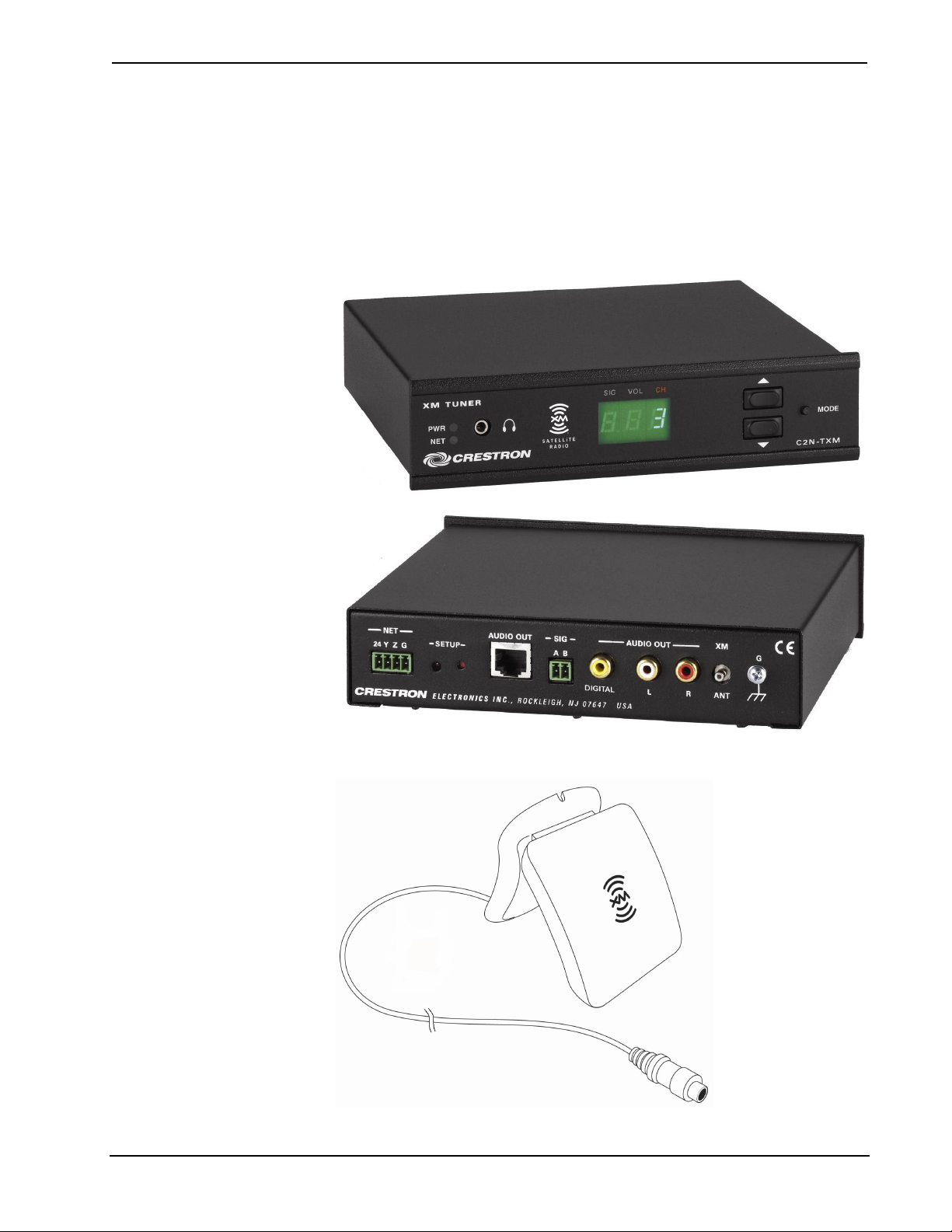
Physical Description
The C2N-TXM is housed in a black enclosure with labeling on the front and rear
panels. Five LEDs on the front of the unit indicate the unit’s status. All connections,
except for headphones, are made on the back of the unit. There are four rubber feet
on the bottom of the unit for stability and to prevent slippage
indoor/outdoor high-gain antenna are illustrated below and on the following page.
C2N-TXM Physical Views
. The unit and the supplied
Supplied Indoor/Outdoor High Gain Antenna
Operations Guide - DOC. 6234A XM Satellite Radio Tuner: C2N-TXM • 3
Page 8
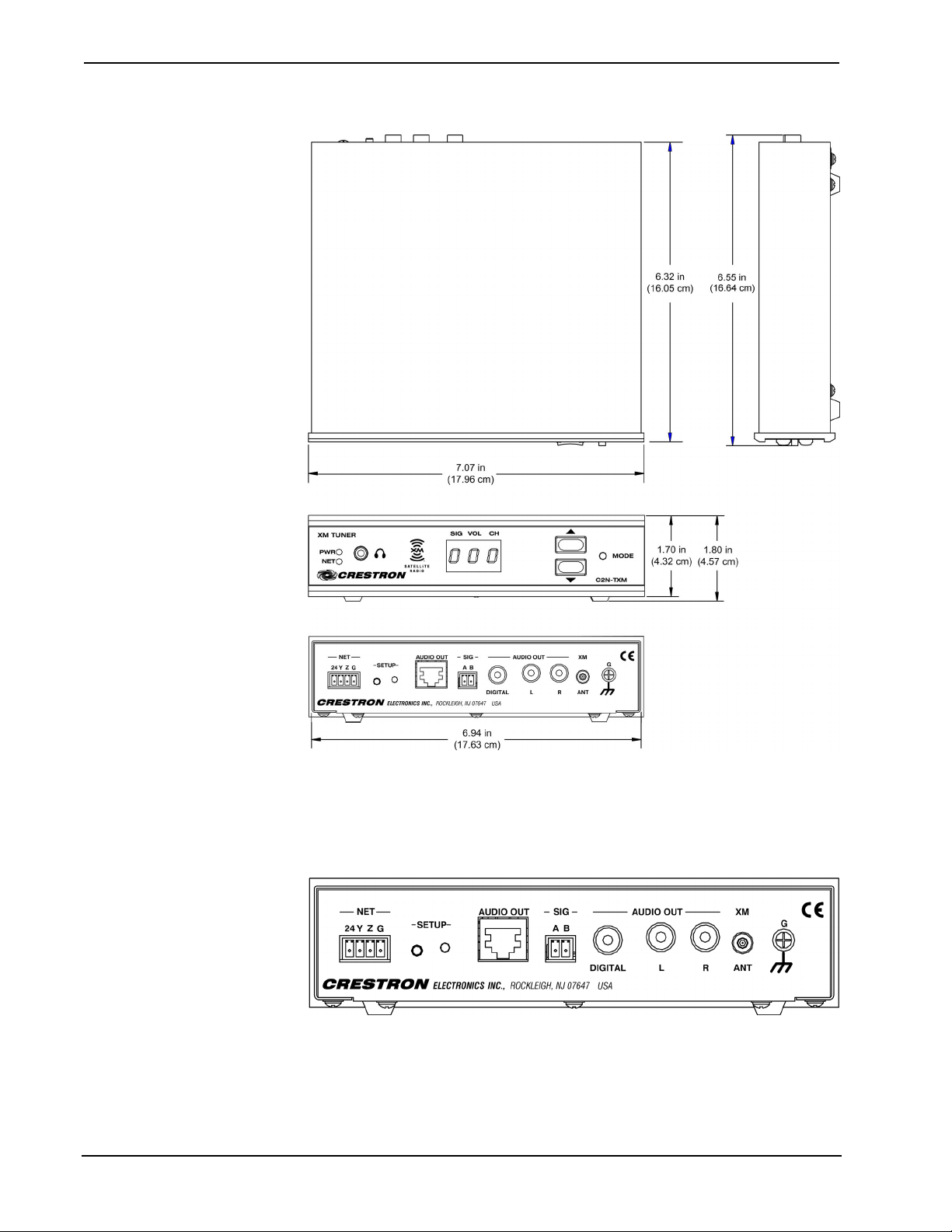
XM Satellite Radio Tuner Crestron C2N-TXM
C2N-TXM Overall Dimensions
C2N-TXM Ports
All connections to the C2N-TXM, except headphones, are made through the ports on
the rear panel. Refer to the illustrations and descriptions, which follow.
C2N-TXM Ports
4 • XM Satellite Radio Tuner: C2N-TXM Operations Guide - DOC. 6234A
Page 9
Crestron C2N-TXM XM Satellite Radio Tuner
NET
This 4-pin terminal block connector is used to connect the C2N-TXM module to the
Cresnet system. Data and power for the C2N-TXM are provided via the connection.
Refer to “Network Wiring” on page 7.
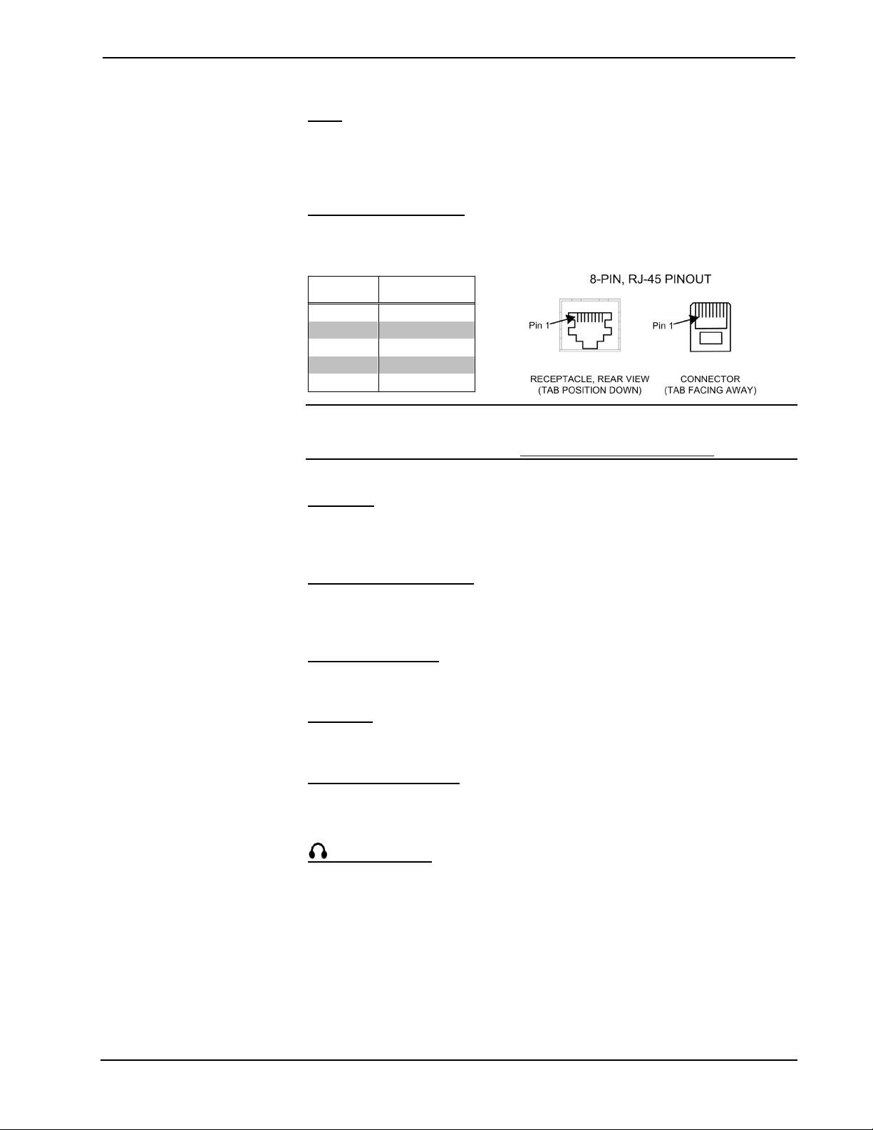
AUDIO OUT (RJ-45)
The RJ-45 AUDIO OUT port is used to route analog stereo to a CNX-BIPAD8 for
distribution throughout the home. Wiring for the connector is shown below.
PIN # SIGNAL
1 Audio Out L +
2 Audio Out L -
3 Audio Out R +
6 Audio Out R -
4, 5, 7, 8 no connection
NOTE: For additional information on audio connections over CAT5, refer to the
latest version of the Crestron CAT5 Wiring Reference Guide (Doc. 6137) which is
available from the Crestron website (http://www.crestron.com/manuals
).
SIG A, B
This two-pin terminal block connector is used for testing signal strength during
antenna installation. Refer to “Antenna Installation” on page 12 for details.
AUDIO OUT DIGITAL
This RCA connector provides S/PDIF coaxial digital stereo output for a local
surround-sound processor such as the C2N-DAP8 or C2N-DAP8RC.
AUDIO OUT L, R
These two RCA connectors provide analog stereo output for local amplifiers.
XM ANT
This RF SMB connector is for the supplied XM antenna cable.
G (Chassis Ground)
Use this chassis screw to ground the unit to the amplifier and audio source common
grounds.
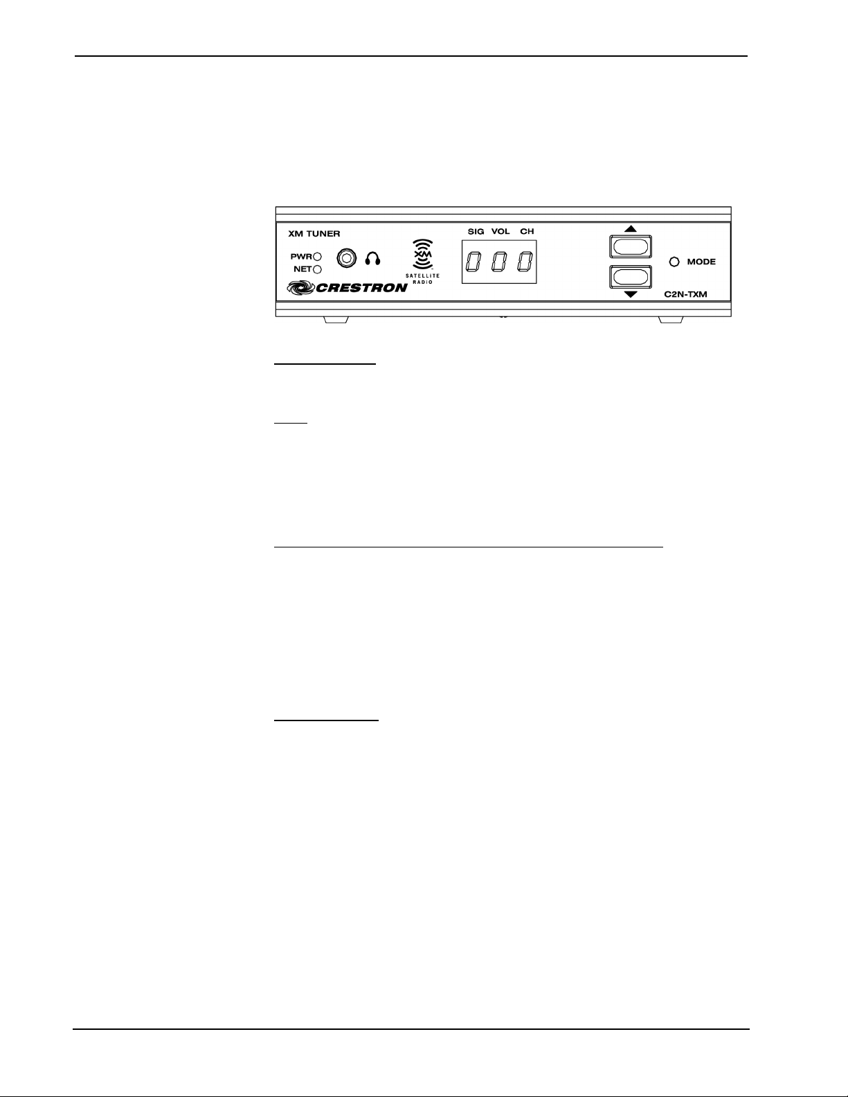
(Headphone)
The only connection on the front panel of the XM Tuner is the mini-phone jack,
which permits the use of headphones to monitor the audio signal. The volume mode,
selected by the MODE switch, allows adjustment of the volume to the headphones.
Note that plugging in headphones does not interrupt the unit’s other audio output
signals.
Operations Guide - DOC. 6234A XM Satellite Radio Tuner: C2N-TXM • 5
Page 10
XM Satellite Radio Tuner Crestron C2N-TXM
Front Panel Controls and Indicators
Five LED indicators, a three-digit display, and three pushbutton switches are located
on the front panel of the C2N-TXM. Refer to the illustration and descriptions that
follow.
C2N-TXM Front Panel Controls and Indicators
PWR (Power)
This green LED illuminates when power is supplied to the C2N-TXM.
NET
This yellow LED illuminates when communication between the control system and
the C2N-TXM is established (the unit is polled on the network). Illumination
indicates that the program currently loaded has a network device defined at the same
ID as the C2N-TXM. The LED flashes or remains on when communication with the
processor occurs.
MODE Switch,
Use the MODE switch to select between the signal, volume, and channel modes. The
corresponding red LEDs (SIG, VOL, and CH) illuminate as each mode is selected. In
each mode, the three-digit display shows the appropriate values. In the channel mode,
the up/down buttons let you sequence through the available channels; the three-digit
display shows the channel numbers. In the volume mode, the up/down buttons select
ten volume levels (0 through 9) for the signal supplied to the headphone jack. In the
signal mode, the display shows an initial letter (Satellite, or repeater) to indicate the
signal source, plus two numeric digits (00 – 99) to indicate the signal strength.
KJ
(Up/Down) Buttons, and Display
SIG, VOL, CH
These red LEDs illuminate in turn when the MODE switch selects the respective
signal, volume, and channel modes.
SETUP LED and Pushbutton
The C2N-TXM is Touch Settable ID (TSID) ready. The SETUP pushbutton and its
associated LED are located on the rear panel and are used for setup of the unit’s
network ID during the initial configuration of a Cresnet system or when the device is
being added/replaced. Refer to “Method B (Touch Settable IDs)” on page 9 for
detailed information.
6 • XM Satellite Radio Tuner: C2N-TXM Operations Guide - DOC. 6234A
Page 11

Crestron C2N-TXM XM Satellite Radio Tuner
Industry Compliance
As of the date of manufacture, the C2N-TXM has been tested and found to comply
with specifications for CE marking and standards per EMC and
Radiocommunications Compliance Labelling.
NOTE: This device complies with part 15 of the FCC rules. Operation is subject to
the following two conditions: (1) these devices may not cause harmful interference,
and (2) these devices must accept any interference received, including interference
that may cause undesired operation.
Setup
Network Wiring
CAUTION: In order to ensure optimum performance over the full range of your
installation topology, Crestron Certified Wire, and only Crestron Certified Wire,
should be used. Failure to do so may incur additional charges if support is required
to identify performance deficiencies as a result of using improper wire.
CAUTION: Use only Crestron power supplies for Crestron equipment. Failure to
do so could cause equipment damage or void the Crestron warranty.
CAUTION: Provide sufficient power to the system. Insufficient power can lead to
unpredictable results or damage to the equipment. Please use the Crestron Power
Calculator to help calculate how much power is needed for the system
(http://www.crestron.com/calculators
NOTE: When installing network wiring, refer to the latest revision of the wiring
diagram(s) appropriate for your specific system configuration, available from the
Crestron website.
When calculating the wire gauge for a particular Cresnet run, the length of the run
and the Cresnet power usage of each network unit to be connected must be taken
into consideration. If Cresnet units are to be daisy-chained on the run, the Cresnet
power usage of each unit to be daisy-chained must be added together to determine
the Cresnet power usage of the entire chain. If the unit is a home-run from a Crestron
system power supply network port, the Cresnet power usage of that unit is the
Cresnet power usage of the entire run. The length of the run in feet and the Cresnet
power usage of the run should be used in the following resistance equation to
calculate the value on the right side of the equation.
Resistance Equation
).
Where:
R <
Operations Guide - DOC. 6234A XM Satellite Radio Tuner: C2N-TXM • 7
L x P
40,000
R = Resistance (refer to the following table).
L = Length of run (or chain) in feet.
P = Cresnet power usage of entire run (or chain).
Page 12

XM Satellite Radio Tuner Crestron C2N-TXM
The required wire gauge should be chosen such that the resistance value is less than
the value calculated in the resistance equation. Refer to the following table.
Wire Gauge Values
RESISTANCE WIRE GAUGE
4 16
6 18
10 20
15 22
13 Doubled CAT5
8.7 Tripled CAT5
NOTE: All Cresnet wiring must consist of two twisted pairs. One twisted pair is the
+24V conductor and the GND conductor, and the other twisted pair is the Y
conductor and the Z conductor.
NOTE: When daisy-chaining Cresnet units, strip the ends of the wires carefully to
avoid nicking the conductors. Twist together the ends of the wires that share a pin on
the network connector, and tin the twisted connection. Apply solder only to the ends
of the twisted wires. Avoid tinning too far up the wires or the end becomes brittle.
Insert the tinned connection into the Cresnet connector and tighten the retaining
screw. Repeat the procedure for the other three conductors.
Refer to the note on page 28 for
a definition of Viewport.
Identity Code
Every equipment and user interface within the network requires a unique identity
code (Net ID). These codes are two-digit hexadecimal numbers from 03 to FE. The
Net ID of each unit must match an ID code specified in the SIMPL Windows
program. Refer to “Setting the Net ID in Device Settings” on page 22 for details of
the SIMPL Windows procedure.
The Net ID of the C2N-TXM has been factory set to 55. The Net IDs of multiple
C2N-TXMs in the same system must be unique. Net IDs are changed from a
personal computer (PC) via the Crestron Viewport.
NOTE: For detailed information on establishing communication between the PC and
control system, refer to “Communication Settings” on page 29. If communication
cannot be established, refer to the “Troubleshooting Communications” section in the
respective Operations Guide for the control system.
There are two different methods—Method A or Method B—for setting the
C2N-TXM Net IDs:
Method A (Cresnet address-settable ID), described on the next page, applies to
C2N-TXMs in a Cresnet system with a CNX control system or with a 2-Series
control system upgrade file (CUZ) version prior to 3.008, but can be used with later
versions of firmware and requires that a single unit be the only network device
connected to the control system.
Method B (Touch Settable IDs), which begins on the next page, applies to
C2N-TXMs in a Cresnet system with 2-Series control system upgrade file (CUZ)
version 3.029 or later. These upgrades enable Touch Settable ID (TSID)
functionality, which makes it possible for the control system to recognize a network
8 • XM Satellite Radio Tuner: C2N-TXM Operations Guide - DOC. 6234A
Page 13

Crestron C2N-TXM XM Satellite Radio Tuner
device via its serial number, which is stored in the device’s memory. This method
does not require that any devices be disconnected from the network; Net IDs may be
set with the entire Cresnet system intact. This method requires the use of the
Crestron Viewport version 3.35 or later.
Use the appropriate method to set the C2N-TXM Net ID.
Method A (Cresnet address-settable ID)
1. Ensure that the C2N-TXM is the only device connected to the control
system.
2. Open the Crestron Viewport.
3. From the Viewport menu, select Functions | Set Network ID. The
software checks the baud rate and then opens the "Set Network ID"
window.
4. In the "Set Network ID" window, select the C2N-TXM from the
Current Network Devices text window.
5. Select the new Net ID for the C2N-TXM from the Choose the new
network ID for the selected device (Hex): text box.
6. Click Set ID to initiate the change. This will display the "ID command
has been sent" window.
7. In the "Command Complete" window, click OK.
8. In the Current Network Devices text window, verify the new Net ID
code.
9. In the "Set Network ID" window, click Close.
NOTE: The new Net ID code may also be verified by selecting Diagnostic |
Report Network Devices in the Viewport (alternately, select F4).
10. Repeat this procedure for each C2N-TXM to be added to the system.
Method B (Touch Settable IDs)
Before using this method, you should have a list of all current network devices and
their Net IDs, to avoid assigning duplicate IDs.
Set Net ID by TSID
These procedures are for TSID-enabled network devices during the initial
configuration of a Cresnet system or when such devices are being added/replaced.
1. Ensure that all C2N-TXMs are connected to the control system.
2. Open the Crestron Viewport version 3.35 or later.
3. From the Viewport menu, select Functions | Assign Cresnet ID by
Serial Number. The “Set Net ID by TSID” window appears. The
window is first displayed with the data fields empty. (Refer to the
figure on the next page.)
Operations Guide - DOC. 6234A XM Satellite Radio Tuner: C2N-TXM • 9
Page 14

XM Satellite Radio Tuner Crestron C2N-TXM
“Set Net ID by TSID” Window
4. Click on the Search for Touch Settable Devices button. The system
searches the network and lists all TSID-enabled devices found. The list
is similar to the report produced by pressing F4 (Report Network
Devices); the first eight digits of each line constitute the TSID number
(hexadecimal form of the serial number).
5. As you enter either the serial number or TSID number of the device
that requires a change, the corresponding TSID or serial number
automatically appears in its appropriate field, and the list scrolls to and
highlights the device listing. The listing should show the device’s
current Cresnet ID.
6. Enter the Cresnet ID that the device should be set to and click OK. The
number you enter should appear on the list.
CAUTION: This function does not prevent you from setting duplicate IDs. Be sure
to check current assignments before entering the desired Cresnet ID number.
Serial Number to TSID Conversion
This utility is useful in a case where there are multiple devices of the same type on a
network, you need to locate a particular one, you know the TSID but not the serial
number, and your site installation list is based on device serial numbers. In this (or
the reverse) situation, do the following:
1. Open the Crestron Viewport.
2. From the Viewport menu, select Functions | Serial Number ÅÆ
TSID Conversion Tool. The “Serial Number ÅÆTSID Conversion
Tool” window is displayed. (Refer to the figure on the next page.)
10 • XM Satellite Radio Tuner: C2N-TXM Operations Guide - DOC. 6234A
Page 15

Crestron C2N-TXM XM Satellite Radio Tuner
“Serial Number to TSID Conversion Tool” Window
3. Enter the serial number or TSID number as instructed; press the
appropriate button to obtain the corresponding number.
NOTE: Enter serial numbers, including spaces, exactly as they appear on the unit
label. Alpha characters in serial numbers or TSID numbers may be entered in upper
or lower case.
Hardware Hookup
Refer to the hookup diagram below. Complete the connections in any order.
Cresnet System Hookup Connections for C2N-TXM
Operations Guide - DOC. 6234A XM Satellite Radio Tuner: C2N-TXM • 11
Page 16

XM Satellite Radio Tuner Crestron C2N-TXM
Antenna Installation
It is important to position the supplied high-gain antenna to receive the strongest
possible signal either from the satellite (preferred) or from a terrestrial repeater
station. This can be done before installing the XM Tuner in your Cresnet system.
Crestron recommends placing the antenna either outside or near a window with a
southern exposure. The antenna should face south if you are in the eastern half of the
continental US, or south/southeast if you are in the western half of the country.
The antenna can be mounted on a horizontal or vertical surface, using screws or
double-faced tape. The following figure shows the antenna mounting plate with
dimensions for mounting screw locations.
Connect the cable of the supplied Remote Sensitivity Indicator to the SIG A and B
connectors on the back of the XM Tuner. Place the indicator near the antenna and
rotate and/or tilt the antenna to obtain the strongest possible signal, as described in
the following table, and secure the antenna in position.
Remote Sensitivity Indicator Operation
SIGNAL
STRENGTH
LED
COLOR STATE
Red On No Signal
Green Off
Red Flashing Weak
Green Off
Red Off Marginal
Green Flashing
Red Off Strong
Green On
Flashing rate is 250 msec (1/4th sec)
(Slow blink)
Flashing rate is 50 msec (1/20th sec)
(Fast blink)
OPERATION
NOTE: The Remote Sensitivity Indicator is supplied with six-inch leads, labeled A
and B. A two-pin terminal block connector is required to plug it in to the SIG A and
B connectors. It may also be necessary to extend the wires if the antenna position is
not within sight of the XM Tuner during adjustment.
NOTE: The supplied antenna has a 20-foot cable. If needed, 50-foot extension
cables, C2N-TXM-C50, are available. Crestron recommends a maximum total length
of 120 feet. Contact a Crestron customer service representative. Alternate antenna
solutions are also available from third-party suppliers. One such source, Antenna
Specialists, can be contacted via their website (www.sdarsantennas.com
12 • XM Satellite Radio Tuner: C2N-TXM Operations Guide - DOC. 6234A
).
Page 17

Crestron C2N-TXM XM Satellite Radio Tuner
When attaching the extension cable, insert the connector from the antenna into the
rubber boot supplied with the extension cable, plug it into the extension cable as
shown, and cover the connection with the rubber boot. Plug the other end of the
extension cable into the XM Tuner XM ANT connector. (Refer to the following
illustration.)
XMGuide Example Program
The XMGuide user interface example program for the XM Tuner demonstrates the
various features of the unit. The program also serves as a model for those individuals
who wish to develop a customized program using Crestron’s programming software.
The XMGuide program supplied for the XM Tuner is designed to operate on a
Crestron TPS-4500 touchpanel (requires firmware version 2.000 or later). If your
Cresnet system uses a different model touchpanel, you may wish to recompile the
project for that touchpanel.
Preparation
In preparation for running the XMGuide, do the following:
1. Complete the procedures detailed in “Setup,” which begins on page 7.
2. Verify that communication setup procedures described in
“Communication Settings” on page 29 have been completed.
3. Download the Example Program from the Crestron website,
http://www.crestron.com/exampleprograms
C2N-TXM.zip).
4. Use the instructions given in “Upload via Crestron Viewport” on page
28, to load the .spz program to the control system and the .vtz program
to the touchpanel.
, (search for
Activating the XM Tuner
When first installed, the XM Tuner is not activated and has limited channel
availability. Set the unit to XM Radio channel 1. This channel broadcasts general
information about XM Radio. To activate, either contact XM Radio on their website
(www.xmradio.com
Channel 0 displays the eight-digit Radio ID number (e.g., RADIO ID A1B12345)
assigned to your XM Tuner in the CHANNEL NAME field. The number is also
printed on the label on the bottom of the unit, and reports back in the Crestron
Operations Guide - DOC. 6234A XM Satellite Radio Tuner: C2N-TXM • 13
) or call (800) 967-2346.
Page 18

XM Satellite Radio Tuner Crestron C2N-TXM
Viewport when Diagnostics | Report Network Devices is selected. Be sure to have
it on hand when you call in to activate the XM Tuner.
Running the XMGuide Example
Once the programs are loaded to the touchpanel and the control system, the main
screen appears on the touchpanel. The following illustration shows the main screen,
with Category Mode selected and a typical display of the Classical category.
XMGuide Example Program Main Screen
The upper left corner of the screen shows the current time and date. The eight-digit
Radio ID number is shown below the time and date display.
The primary selection controls for the XMGuide are located on the left side of the
display. Volume up/down buttons (k j) and a graphic display plus a Mute button
are located at the lower left corner of the screen.
Category
Press the Category selector to display a list of all the available categories. The
current category and program information is displayed above the category listing, as
shown in the figure on the next page.
14 • XM Satellite Radio Tuner: C2N-TXM Operations Guide - DOC. 6234A
Page 19

Crestron C2N-TXM XM Satellite Radio Tuner
Press a category name to see a list of all programs available within that category.
(Refer to the figure below.)
Use the Page Up and Page Down buttons (kj to select additional pages (if any);
use the First and Last buttons to jump to the first or last page of the list (if
necessary).
Operations Guide - DOC. 6234A XM Satellite Radio Tuner: C2N-TXM • 15
Page 20

XM Satellite Radio Tuner Crestron C2N-TXM
Channel
Press the Channel selector to display a channel selection keypad.
The current channel and program information is displayed above the keypad. The
Signal Strength graphic indicator to the left of the keypad shows the signal level of
the Repeater and Satellite signals.
On the keypad, key in a number and press the Enter button to select a new channel;
press Clear to clear the entry field if you make a mistake.
Presets
The Presets feature allows you to specify up to twenty channels that you wish to
select quickly. You can also specify up to twenty “favorite” artists or programs.
Press the Presets selector to display the first six channel presets. Initially, each one
is set to XM Preview. To set up the presets, follow the on-screen directions: tune in a
station and press and hold an available preset field for five seconds to save it.
To save more than six presets, press the More... button. The screen changes to a
display of twenty Preset fields. The currently selected channel and program
information is displayed above the list of presets.
16 • XM Satellite Radio Tuner: C2N-TXM Operations Guide - DOC. 6234A
Page 21

Crestron C2N-TXM XM Satellite Radio Tuner
You can also specify up to twenty “favorite” artists and/or programs. Using any
method of tuning in to a channel, select a channel where the title or name is one that
you want to include in your list of favorites. Then, on the screen that displays all
your Presets, press the Set Up Favorites button. The display changes to a screen that
allows you to identify favorite artists or titles. Press the Save Name or Save Title
button as appropriate. The saved title or artist name appears in the field to the right.
The figure below shows a portion of the screen with two favorites saved. Whenever
a “favorite” artist or program title is playing, the XMGuide highlights the Preset
channel to alert you so you can select it if you wish.
All Channels
Press the All Channels selector to display a list of all the available channels. The
display is like the one for a specific category, but lists all channels and categories in
channel number order. The current category and program information is displayed
above the channel listing. Use the Page kj buttons to select additional pages; use
the First and Last buttons to jump to the first or last page of the list.
Tech Page
The Tech Page is intended for trained individuals to perform system diagnostics.
Operations Guide - DOC. 6234A XM Satellite Radio Tuner: C2N-TXM • 17
Page 22

XM Satellite Radio Tuner Crestron C2N-TXM
Quick Page
This screen provides quick selection control of all available channels and categories.
Also displayed are the title and artist names of the current selection, and signal
strength from satellite and terrestrial sources. The screen and its buttons and displays
are described below.
Power
Use this button to turn power to the XM Tuner on and off. (If power is removed and
then reapplied, the green BUSY indicator briefly turns red as the XM Tuner cycles
through its initialization process.) The XM Tuner start-up default is the last channel
that was in use prior to power down.
Category
With category mode enabled (see below), use these buttons to search up and down
through the various program categories. Hold either button down to scroll
continuously through all the categories.
NOTE: Each time you press a channel or category button, the green BUSY indicator
adjacent to the channel selection buttons briefly turns red as the XM Tuner mutes the
audio and tunes to the new channel.
KJ
Category Mode
Use this button to enable/disable selection of program categories. (In category mode,
only those channels that are in the selected category are available for selection via
the Channel KJ buttons. When category mode is disabled, these buttons can select
all channels.)
Channel
Use these buttons to search up and down through the available XM channels.
(Channel availability depends on subscription. A non-subscribed radio typically
provides only five sample channels in addition to the standard channels 0 and 1.
18 • XM Satellite Radio Tuner: C2N-TXM Operations Guide - DOC. 6234A
KJ
Page 23

Crestron C2N-TXM XM Satellite Radio Tuner
Either contact XM Radio on their website (www.xmradio.com) or call (800)
967-2346. Hold either button down to scroll continuously through the list.)
(In category mode, only those channels that are in the selected category are available
for selection via the Channel KJ buttons. When category mode is disabled, these
buttons can select all channels.)
Mute
Use this button to mute/unmute the audio signal.
Display Fields
The CATEGORY field at the top center of the screen displays the name of the
categories as you select them. When you select a category, the Channel KJ buttons
(above) select the available channels only within that category.
The Terrestrial and Satellite graphical and digital displays show the relative
strength (0 to 100%) of the signal received from the satellite or the terrestrial
repeater station. The XM Tuner automatically chooses the strongest signal for
processing.
The CHANNEL and CHANNEL NAME fields display the XM Radio channel
number and the name of the channels as you select them, the TITLE field displays
the name of the selection currently playing, and the NAME field displays the name
of the artist performing the selection. (Some selection and title names may be
abbreviated.)
Keypad
You can also enter a specific channel number using the keypad at the bottom of the
screen. Select the channel number and press ent to enter the selection. Your
selections appear in the blue field as you enter them. Press clr to clear your selection
if you make a mistake.
Program
Press the Program button at the top right of the screen to enable programming of up
to twenty presets of your favorite channel selections. Note that this is not a
momentary button: you must press it again to turn off programming.
To program your presets, enable programming with the Program button and search
through the various categories and channels. When you find a “favorite,” press one
of the twenty preset buttons. The button name changes to the “favorite” channel name.
When you finish programming presets, be sure to press Program again to turn off the
feature. Alternatively, press and hold a preset button for about five seconds to
automatically program the preset without having to first enable programming.
NOTE: You can program preset channels from among any of the categories.
Channel selection using the preset buttons is not affected by the state of category
mode.
RETURN
Press this button to return to the main screen of the XMGuide.
Operations Guide - DOC. 6234A XM Satellite Radio Tuner: C2N-TXM • 19
Page 24

XM Satellite Radio Tuner Crestron C2N-TXM
p
Programming Software
Have a question or comment about Crestron software?
Answers to frequently asked questions (FAQs) can be viewed in the Online Help
section of the Crestron website. To post a question or view questions you have
submitted to Crestron’s True Blue Support, log in at http://support.crestron.com.
First-time users will need to establish a user account.
You can create a program that allows you to include the C2N-TXM in a Crestron
control system using the Crestron programming tools Crestron SystemBuilder™ and
SIMPL Windows. These tools are intended for users with different levels of
programming knowledge. The flexibility of each tool is proportional to the degree of
programming expertise (i.e., the more flexible, the more a programmer needs to
know and account for). Of course, one can initiate programming using the easiest
method (SystemBuilder) and use advanced techniques that are available from
SIMPL Windows to customize the job.
Earliest Version Software Requirements for the PC
The easiest method of
rogramming, but does not
offer as much flexibility as
SIMPL Windows.
NOTE: Crestron recommends that you use the latest software to take advantage of
the most recently released features. The latest software is available from the Crestron
website.
The following are recommended software version requirements for the PC:
• (Optional) SystemBuilder version 2.00 or later. Requires SIMPL
Windows (version 2.06.05 or later) and Crestron Engraver. Requires
SystemBuilder templates 1.01 or later.
• SIMPL Windows version 2.05.16 or later.
Requires SIMPL+ Cross Compiler version 1.1.
• Crestron Database version 16.1.0 or later. Required by SIMPL
Windows.
Programming with the Crestron SystemBuilder
The Crestron SystemBuilder offers automatic programming for such residential and
commercial applications as audio distribution, home theater, video conferencing,
and lighting. The interface of this tool guides you through a few basic steps for
designating rooms and specifying the control system, touchpanels, devices, and
functionality. SystemBuilder then programs the system, including all touchpanel
projects and control system logic.
SystemBuilder is fully integrated with Crestron's suite of software development
tools, including SIMPL Windows, VT Pro-e, Crestron Database, User IR Database,
and User Modules Directory. SystemBuilder accesses these tools behind the scenes,
enabling you to easily create robust systems.
SystemBuilder includes Scheduler programming which allows you to define weekly,
periodic, or by-date events that run at scheduled times of day. Scheduler properties
can be adjusted via a touchpanel. Refer to the extensive SystemBuilder help file for
details.
20 • XM Satellite Radio Tuner: C2N-TXM Operations Guide - DOC. 6234A
Page 25

Crestron C2N-TXM XM Satellite Radio Tuner
Programming with SIMPL Windows
NOTE: The following are acceptable file extensions for programs that include a
C2N-TXM, developed for specific control system types:
.smw projectname.smw (source file)
.spz projectname.spz (compiled file for 2-Series)
.bin projectname.bin (compiled file for CNX generation)
.csz projectname.csz (compiled file for CNX generation with SIMPL+)
.ush projectname.ush (compiled file for CNX generation with SIMPL+
header file)
.usp projectname.usp (source code module for SIMPL+)
SIMPL Windows is Crestron's software for programming Crestron control systems.
It provides a well-designed graphical environment with a number of workspaces
(i.e., windows) in which a programmer can select, configure, program, test, and
monitor a Crestron control system. SIMPL Windows offers drag and drop
functionality in a familiar Windows
NOTE: The following descriptions assume that the reader has knowledge of
SIMPL Windows. If not, refer to the extensive help information provided with the
software.
®
environment.
NOTE: In the following description, the PRO2 control system is used.
This section describes a sample SIMPL Windows program that includes a
C2N-TXM.
Configuration Manager is where programmers “build” a Crestron control system by
selecting hardware from the Device Library. In Configuration Manager, drag the
PRO2 from the Control Systems folder of the Device Library and drop it in the
upper pane of the System Views. The PRO2 with its associated communication ports
is displayed in the System Views upper pane.
PRO2 System View
The System Views lower pane displays the PRO2 system tree (refer to graphic
below). This tree can be expanded to display and configure the communications
ports.
Expanded PRO2 System Tree
Operations Guide - DOC. 6234A XM Satellite Radio Tuner: C2N-TXM • 21
Page 26

XM Satellite Radio Tuner Crestron C2N-TXM
C2Net Device Slot in Configuration Manager
To incorporate a C2N-TXM into the system, drag the C2N-TXM from the Cresnet
Control Modules | Cresnet Audio Modules folder of the Device Library and drop it
in System Views. The PRO2 system tree displays the C2N-TXM in Slot 9, with a
default Net ID of 55 as shown in the following illustration.
NOTE: The first C2N-TXM in a system is preset with a Net ID of 55 when its
symbol is dragged into the upper pane of System Views. Additional units are
assigned different Net ID numbers as they are added.
C2Net Device, Slot 9
Setting the Net ID in Device Settings
Double-click the C2N-TXM icon to open the “Device Settings” window. This
window displays the C2N-TXM device information. If necessary, select the Net ID
tab to change the C2N-TXM Net ID, as shown in the figure below.
C2N-TXM “Device Settings” Window
NOTE: SIMPL Windows automatically changes Net ID values of a device added to
a program if a duplicate device or a device with the same default Net ID already
exists in the program. Always ensure that the hardware and software settings of the
Net ID match. For Net ID hardware setting details, refer to “Identity Code” on
page 8.
C2N-TXM Symbol in Programming Manager
Programming Manager is where programmers “program” a Crestron control system
by assigning signals to symbols. The C2N-TXM symbol in the SIMPL Windows’
Programming Manager is extensive and is illustrated in three sections, beginning on
the next page. Tables defining the input and output signals follow each section.
22 • XM Satellite Radio Tuner: C2N-TXM Operations Guide - DOC. 6234A
Page 27

Crestron C2N-TXM XM Satellite Radio Tuner
C2N-TXM Digital Input and Output Signals
Operations Guide - DOC. 6234A XM Satellite Radio Tuner: C2N-TXM • 23
Page 28

XM Satellite Radio Tuner Crestron C2N-TXM
C2N-TXM Digital Input and Output Signal Descriptions
SIGNAL TYPE
AND NAME DESCRIPTION
Digital input: <Power>
Digital output:
<PowerUpBusy>
Digital output:
<TuningBusy>
Digital input:
<Mute>
Digital input:
<GetTime>
Digital inputs:
<ChanUp>,
<ChanDown>
Digital input:
<CatMode>
Digital inputs:
<CatUp>,
<CatDown>
Digital inputs:
<ProgMode>
Digital inputs:
<Preset1> through
<Preset20>
Digital input:
<EnableGuide>
Digital input:
<ISOConvOff>
Digital input:
<DiagMode>
(continued on next page)
Turns power on and off.
High/1 = Power on; Low/0 = Power off
Indicates that the C2N-TXM is busy powering up.
High/1 = Powering up (busy); Low/0 = Ready (done)
Indicates that the C2N-TXM is busy tuning to a station.
High/1 = Tuning (busy); Low/0 = Ready (done)
Audio mute on and off.
High/1 = Mute on; Low/0 = Mute off (play)
Requests the current time and date from the XM satellite, on the
rising edge of the signal. The time and date, in Greenwich Mean
Time (GMT), are sent to the <Time> analog outputs described
later.
High/1 = Get time; Low/0 = not used
Channel up and down controls.
Channels change up and down with each rising edge of the
signal. If the signal is held high (> 0.5 sec.), the channels cycle up
or down continuously, for as long as the signal is asserted.
High/1 = Start channel up or down;
Low/0 = Stop channel up or down
Enables category mode for as long as the input is high, and
activates the <CatUp> and <CatDown> category selection inputs
described next.
High/1 = Enter category mode; Low/0 = Exit category mode
Category up and down controls, enabled if in category mode.
Categories change up and down with each rising edge of the
signal. If the signal is held high (> 0.5 sec.), the categories cycle
up or down continuously, for as long as the input is asserted.
High/1 = Start category up or down;
Low/0 = Stop category up or down
Enables programming mode, which saves the current channel
number to whichever <Preset> input goes high.
High/1 = Enter programming mode;
Low/0 = Exit programming mode
Saves/plays presets on the rising edge of the signal.
Saves the preset if in programming mode; otherwise plays the
preset.
High/1 = Save or play preset; Low/0 = not used
When connected to the "XM Guide" SIMPL+ module, this input
enables the XM Program Guide feature.
The Program Guide can update indirect text for a scrolling guide
to all channels, a list of presets, a guide to all categories and the
songs in each category. It also supports direct entry of channel
numbers via a keypad. In addition, a list of favorite songs or
artists can be maintained. For further information, refer to the F1
help for the "XM Guide" module.
High/1 = Enable program guide; Low/0 = Disable program guide
Turns off ISO conversion, which converts ISO characters 128-255
into ASCII characters 0-127. (The Arial font family supports ISO
conversion.)
High/1 = ISO conversion OFF; Low/0 = ISO conversion ON
Enables diagnostic mode, which retrieves diagnostic data from
the XM Radio controller embedded device, and activates the
<DiagScroll> inputs described next.
High/1 = Enter diagnostics mode; Low/0 = Exit diagnostics mode
24 • XM Satellite Radio Tuner: C2N-TXM Operations Guide - DOC. 6234A
Page 29

Crestron C2N-TXM XM Satellite Radio Tuner
C2N-TXM Digital Input and Output Signal Descriptions (continued)
SIGNAL TYPE
AND NAME DESCRIPTION
Digital inputs:
<DiagScrollUp>,
<DiagScrollDown>
Digital inputs:
<HeadVolUp>,
<HeadVolDn>
C2N-TXM Analog Input and Output Signals
Scrolls through diagnostic data messages 1 through 8,
generated by the XM Radio controller embedded device. The
data is routed to the <DiagStrings> serial output described
later.
The data scrolls up or down on the rising edge of the signal. If
the signal is held high, the data will cycle up or down
continuously for as long as the signal is asserted.
High/1 = Start scrolling up or down;
Low/0 = Stop scrolling up or down
Headphone volume controls.
Headphone volume is adjusted up or down on the rising edge of
the signal.
High/1 = Volume Up or Down; Low/0 = not used
Operations Guide - DOC. 6234A XM Satellite Radio Tuner: C2N-TXM • 25
Page 30

XM Satellite Radio Tuner Crestron C2N-TXM
C2N-TXM Analog Input and Output Signal Descriptions
SIGNAL TYPE AND
NAME DESCRIPTION
Analog input:
<ChannelReq>
Analog inputs:
<ChanNmLen>,
<ChanSongNmLen>
Analog input:
<GuideRptRate>
Analog output: <Channel>
Analog outputs: <RepSignal>,
<SatSignal>
Analog outputs: <TimeSec>,
<TimeMin>, <TimeHr>,
<TimeDay>, <TimeMonth>,
<TimeYear>
Analog output: <Status>
(continued on next page)
Tunes to the channel defined by the analog value.
Valid values range from 0 to 255, although the number of
available channels may be less. (Channel 0 is the Radio ID
channel, which provides XM Radio licensing information.)
The <ChanNmLen> input gives the maximum number of
characters allowed in the <ActChanName> and
<PresetName> strings described later.
The <ChanSongNmLen> input gives the maximum
number of characters allowed in the <ActChanCat>,
<ActChanSong>, <ActChanArtist> and <ActChanNum>
strings described later.
Valid values are 8 or 16, indicating a maximum of 8 or 16
characters.
No other values are valid for <Len>.
When connected to the "XM Guide" SIMPL+ module, this
analog sets the report rate, in milliseconds, for data being
sent to the XM radio program guide. Reporting is enabled
only when the <EnableGuide> input is set to high. The
report rate defaults to 200 milliseconds if
<GuideRptRate> is unconnected or set to 0. Otherwise,
valid values range from 100 to 10,000.
Indicates the current channel number.
Indicates the strength of the ground repeater signal and
satellite signal.
Valid values range from 0 to 65535, which can be mapped
to 0% to 100% and routed to a bargraph on the
touchpanel.
These analogs report the current time and date (in
Greenwich Mean Time) on the rising edge of the
<GetTime> input. When connected to the "XM GMT
Time" SIMPL+ module, the module can use the time data
to set the control system's master time clock. For further
information, refer to the F1 help for the module.
<TimeSec> gives the real time clock reading for seconds
and ranges from 0 to 59.
<TimeMin> gives the real time clock reading for minutes
and ranges from 0 to 59.
<TimeHr> gives the real time clock reading for hours and
ranges from 0 to 23.
<TimeDay> gives the real time clock reading for the
current day and ranges from 1 to 31.
<TimeMonth> gives the real time clock reading for the
current month and ranges from 1 to 12.
<TimeYear> gives the real time clock reading for the
current year, starting with 2003
Used for advanced diagnostics and debugging. Status
and error messages are taken from the lower 10 bits of
the analog value.
Bits 0 through 3 indicate signal strength:
0 = No signal
1 = Weak signal
2 = Marginal signal
3 = Full signal
Bits 4 through 10 indicate error messages:
Bit 4: 1 = No Antenna
Bit 9: 1 = Activation required
26 • XM Satellite Radio Tuner: C2N-TXM Operations Guide - DOC. 6234A
Page 31

Crestron C2N-TXM XM Satellite Radio Tuner
C2N-TXM Analog Input and Output Signal Descriptions (continued)
SIGNAL TYPE AND
NAME DESCRIPTION
Analog outputs:
<Preset1Chan> through
<Preset20Chan>
C2N-TXM Serial Input and Output Signals
Indicates the channel number of the corresponding preset.
These values can range from 0 (for the Radio ID channel)
to 255.
Operations Guide - DOC. 6234A XM Satellite Radio Tuner: C2N-TXM • 27
Page 32

XM Satellite Radio Tuner Crestron C2N-TXM
C2N-TXM Serial Input and Output Signal Descriptions
SIGNAL NAME DESCRIPTION
Serial input: <GuideFocusLst>
Serial outputs:
<ActChanName>,
<ActChanCat>,
<ActChanSong>,
<ActChanArtist>,
<ActChanNum>
Serial output:
<GuideInfo>
Serial output:
<DiagStrings>
Serial outputs:
<Preset1Name> through
<Preset20Name>
When connected to the "XM Guide" SIMPL+ module, this
string enables the module to tell the XM radio which
stations are currently shown in the display. The
information for these stations has priority over all other
information, so that the visible display is accurate and upto-the-second. The first byte in this string is an STX
character followed by an A0 character. Each remaining
byte is the channel number of a displayed station. A
maximum of 30 channels is allowed. The string ends with
an ETX character.
The program guide is enabled only when the
<EnableGuide> input is set to high. The data is reported
to the program guide at the rate set by <GuideRptRate>.
Indicates the current channel name and number,
category, song title and artist.
Each string can have a maximum of 8 or 16 characters, as
set in the <Len> analogs described earlier.
When connected to the "XM Guide" SIMPL+ module, this
string displays program guide information, including
category, artist, song title, category flags, status codes
and other data.
XM Guide information is enabled only when the
<EnableGuide> input is set to high.
When in diagnostic mode, this strings displays diagnostic
messages 1 through 8 generated by the XM radio
controller embedded device.
Diagnostic mode is enabled only when <DiagMode> is
set to high. The <Scroll> analogs scroll through the data.
Indicates the channel name of the corresponding preset.
Each string can have a maximum of 8 or 16 characters, as
set in the <Len> analogs described earlier.
Uploading and Upgrading
NOTE: Crestron recommends that you use the latest software and that each device
contains the latest firmware to take advantage of the most recently released features.
Please check the Crestron website (http://www.crestron.com/updates
versions of software and firmware. New users are required to register to obtain
access to this site.
Assuming a PC is properly connected to the entire system, Crestron programming
software allows the programmer to upload programs and projects after their
development to the system and network devices. However, there are times when the
files for the program and projects are compiled and not uploaded. Instead, compiled
files may be distributed from programmers to installers, from Crestron to dealers,
etc. Even firmware upgrades are available from the Crestron website as new features
are developed after product releases. In those instances, one has the option to upload
via the programming software or to upload and upgrade via the Crestron Viewport.
NOTE: The Crestron Viewport is available as a pull-down command from SIMPL
Windows and VT Pro-e (Tools | Viewport) or as a standalone utility. The Viewport
utility accomplishes multiple system tasks, primarily via an RS-232 or TCP/IP
connection between the control system and a PC. It is used to observe system
28 • XM Satellite Radio Tuner: C2N-TXM Operations Guide - DOC. 6234A
) for the latest
Page 33

Crestron C2N-TXM XM Satellite Radio Tuner
processes, upload new operating systems and firmware, change system and network
parameters, and communicate with network device consoles and touchpanels, among
many other tasks. Viewport can also function as a terminal emulator for generic file
transfer. All of these functions are accessed through the commands and options in
the Viewport menus. Therefore, for its effectiveness as a support and diagnostic tool,
the Crestron Viewport may be preferred over development tools when uploading
programs and projects.
The following sections define how one would upload a SIMPL Windows program or
upgrade the firmware of the C2N-TXM. However, before attempting to upload or
upgrade, it is necessary to establish communications.
Communication Settings
NOTE: For laptops and other PCs without a built-in RS-232 port, Crestron
recommends the use of PCMCIA cards, rather than USB-to-serial adapters. If a
USB-to-serial adapter must be used, Crestron has tested the following devices with
good results:
Belkin (large model) F5U103
I/O Gear GUC232A (discontinued)
Keyspan USA-19QW (discontinued)
Other models, even from the same manufacturer, may not yield the same results.
The procedure in this section provides details for RS-232 communication between
the PC and the control system. If TCP/IP communication is preferred, consult the
latest version of the Crestron e-Control Reference Guide (Doc. 6052) or the
respective Operations Guide for the control system. These documents are available
from the Crestron website. Refer to the following figure for a typical connection
diagram when uploading files.
NOTE: Use a standard DB9 male to female “straight-through” cable.
Typical Connection Diagram when Uploading
Operations Guide - DOC. 6234A XM Satellite Radio Tuner: C2N-TXM • 29
Page 34

XM Satellite Radio Tuner Crestron C2N-TXM
1. Open the Crestron Viewport.
Either launch the stand-alone version of Viewport, or start SIMPL
Windows or VT Pro-e, and from the menu bar, select Tools |
Viewport.
2. Refer to the figure after this step. From the Viewport menu, select
Setup | Communications settings (alternatively, press Alt+D) to open
the “Port Settings” window.
Setup | Communications Settings Command
3. Select RS-232 as the connection type. Verify that an available COM
port (COM 1 is shown after this step) is selected, and that all
communication parameters and necessary options from the “Port
Settings” window are selected as shown below. Click the OK button to
save the settings and close the window.
“Port Settings” Window
NOTE: The parameters shown in the illustration above are the port settings for a
2-Series control system. Consult the Operations Guide for the control system being
used for exact parameter selection.
30 • XM Satellite Radio Tuner: C2N-TXM Operations Guide - DOC. 6234A
Page 35

Crestron C2N-TXM XM Satellite Radio Tuner
4. To verify communication, select Diagnostics | Establish
Communications (Find Rack). This should display a window that
gives the COM port and baud rate. If communication cannot be
established, refer to the “Troubleshooting Communications” section in
the respective Operations Guide for the control system.
Uploading a SIMPL Windows Program
A control system source file has
the extension .smw. A compiled
SIMPL Windows file has the
extension .spz for a 2-Series
control system, .bin for CNX
generation, and .csz for CNX
generation with SIMPL+.
The SIMPL Windows file can be uploaded to the control system using SIMPL
Windows or via the Crestron Viewport.
Upload via SIMPL Windows
1. Start SIMPL Windows.
2. Select File | Open to view the “Open” window, navigate to the SIMPL
Window file (.smw), and click Open.
3. Select Project | Transfer Program.
Upload via Crestron Viewport
1. Verify that the procedure for “Communication Settings” that begins on
page 29 has been performed.
2. As shown after this step, select File Transfer | Send Program
(alternatively, press Alt+P) from the Viewport menu.
File Transfer | Send Program Command
3. The “Send Program” window appears, as shown after this step. Click
Browse, locate the compiled file (.spz for PRO2), and click Open. This
will display the program's header information and enable one or both of
the What to Send check boxes. If the program does not contain any
SIMPL+ modules, only the SIMPL Program check box will be
enabled. If it does contain SIMPL+ modules, then the SIMPL+
Program(s) check box will also be enabled. Select one or both check
boxes and then click Send Program to begin the transfer.
NOTE: Refer to the respective Operations Guide for the control system for details
about the other fields shown on the “Send Program” window.
Operations Guide - DOC. 6234A XM Satellite Radio Tuner: C2N-TXM • 31
Page 36

XM Satellite Radio Tuner Crestron C2N-TXM
“Send Program” Window
4. To verify that the program has been transferred successfully, select
Diagnostics | Report Program Information. This should display a
window that provides details about the current program loaded into the
control system.
A firmware upgrade file has the
extension .upg.
Firmware Upgrade
To take advantage of all the available features, it is important that the unit contains
the latest firmware. Please check the Crestron website for the latest version of
firmware. Not every product has a firmware upgrade, but as Crestron improves
functions, adds new features, and extends the capabilities of its products, firmware
upgrades are posted. To upgrade the firmware, complete the following steps.
1. Make sure that “Communication Settings” that begins on page 29 has
been performed.
2. As shown after this step, select File Transfer | Load Network Device
from the Viewport menu.
File Transfer | Load Network Device Command
3. As shown after this step, select the Net ID of the C2N-TXM and then
click OK. The “Open” window appears (refer to the subsequent
graphic).
32 • XM Satellite Radio Tuner: C2N-TXM Operations Guide - DOC. 6234A
Page 37

Crestron C2N-TXM XM Satellite Radio Tuner
“Select Network ID” Window
NOTE: When transferring any Cresnet file (touchpanel project/firmware), lower the
port speed baud rate to 38400 to match the Cresnet bus speed.
“Open” Window
4. Browse to the desired .upg file and click Open to begin the transfer.
Operations Guide - DOC. 6234A XM Satellite Radio Tuner: C2N-TXM • 33
Page 38

XM Satellite Radio Tuner Crestron C2N-TXM
Problem Solving
Troubleshooting
The following table provides corrective action for possible trouble situations. If
further assistance is required, please contact a Crestron customer service
representative.
C2N-TXM Troubleshooting
TROUBLE
does not
illuminate.
Yellow NET LED
does not
illuminate.
Receiving only XM
channels 0 and 1
and, at most, five
other channels
that change every
four hours or so.
Cannot tune in to a
channel.
Display goes off
and there is no
audio.
PROBABLE
CAUSE(S)
Wrong power supply. Use a Crestron power supply. Green PWR LED
C2N-TXM is not receiving
power.
Improper Net ID. Verify that the C2N-TXM Net ID matches
Loose network
connection.
The XM Tuner is not
activated.
Unauthorized to receive
that channel, or the
channel is blocked.
(Affects only those radios
that are left on all the
time.) XM Radio connection needs to be reestablished every 24 hours.
CORRECTIVE ACTION
Verify that cables plugged into NET port
are secure.
Net ID in the software program.
Verify that cable plugged into NET port is
secure.
Activate the XM Tuner as described in
“Activating the XM Tuner” on page 13.
Contact XM Radio on their website
(www.xmradio.com) or call (800)
967-2346.
1. Manually recycle power to the XM
Radio
once every 24 hours.
2. Add
SIMPL logic to program to turn
power off and then back on once
every 24 hours.
Further Inquiries
If you cannot locate specific information or have questions after reviewing this
guide, please take advantage of Crestron's award winning customer service team by
calling the Crestron corporate headquarters at 1-888-CRESTRON [1-888-273-7876].
For assistance in your local time zone, refer to the Crestron website
(http://www.crestron.com/
) for a listing of Crestron worldwide offices.
You can also log onto the online help section of the Crestron website to ask
questions about Crestron products. First-time users will need to establish a user
account to fully benefit from all available features.
Future Updates
As Crestron improves functions, adds new features, and extends the capabilities of
the C2N-TXM, additional information and programming examples may be made
available as manual updates. These updates are solely electronic and serve as
intermediary supplements prior to the release of a complete technical documentation
revision.
Check the Crestron website periodically for manual update availability and its
relevance. Updates are identified as an “Addendum” in the Download column.
34 • XM Satellite Radio Tuner: C2N-TXM Operations Guide - DOC. 6234A
Page 39

Crestron C2N-TXM XM Satellite Radio Tuner
Return and Warranty Policies
Merchandise Returns / Repair Service
1. No merchandise may be returned for credit, exchange, or service without prior
authorization from CRESTRON. To obtain warranty service for CRESTRON
products, contact the factory and request an RMA (Return Merchandise
Authorization) number. Enclose a note specifying the nature of the problem, name
and phone number of contact person, RMA number, and return address.
2. Products may be returned for credit, exchange, or service with a CRESTRON Return
Merchandise Authorization (RMA) number. Authorized returns must be shipped
freight prepaid to CRESTRON, 6 Volvo Drive, Rockleigh, N.J., or its authorized
subsidiaries, with RMA number clearly marked on the outside of all cartons.
Shipments arriving freight collect or without an RMA number shall be subject to
refusal. CRESTRON reserves the right in its sole and absolute discretion to charge a
15% restocking fee, plus shipping costs, on any products returned with an RMA.
3. Return freight charges following repair of items under warranty shall be paid by
CRESTRON, shipping by standard ground carrier. In the event repairs are found to
be non-warranty, return freight costs shall be paid by the purchaser.
CRESTRON Limited Warranty
CRESTRON ELECTRONICS, Inc. warrants its products to be free from manufacturing defects in
materials and workmanship under normal use for a period of three (3) years from the date of
purchase from CRESTRON, with the following exceptions: disk drives and any other moving or
rotating mechanical parts, pan/tilt heads and power supplies are covered for a period of one (1)
year; touchscreen display and overlay components are covered for 90 days; batteries and
incandescent lamps are not covered.
This warranty extends to products purchased directly from CRESTRON or an authorized
CRESTRON dealer. Purchasers should inquire of the dealer regarding the nature and extent of the
dealer's warranty, if any.
CRESTRON shall not be liable to honor the terms of this warranty if the product has been used in
any application other than that for which it was intended, or if it has been subjected to misuse,
accidental damage, modification, or improper installation procedures. Furthermore, this warranty
does not cover any product that has had the serial number altered, defaced, or removed.
This warranty shall be the sole and exclusive remedy to the original purchaser. In no event shall
CRESTRON be liable for incidental or consequential damages of any kind (property or economic
damages inclusive) arising from the sale or use of this equipment. CRESTRON is not liable for any
claim made by a third party or made by the purchaser for a third party.
CRESTRON shall, at its option, repair or replace any product found defective, without charge for
parts or labor. Repaired or replaced equipment and parts supplied under this warranty shall be
covered only by the unexpired portion of the warranty.
Except as expressly set forth in this warranty, CRESTRON makes no other warranties, expressed
or implied, nor authorizes any other party to offer any warranty, including any implied warranties
of merchantability or fitness for a particular purpose. Any implied warranties that may be imposed
by law are limited to the terms of this limited warranty. This warranty statement supercedes all
previous warranties.
Trademark Information
All brand names, product names, and trademarks are the sole property of their respective owners. Windows is a registered
trademark of Microsoft Corporation. Windows95/98/Me/XP and WindowsNT/2000 are trademarks of Microsoft
Corporation.
Operations Guide - DOC. 6234A XM Satellite Radio Tuner: C2N-TXM • 35
Page 40

Crestron Electronics, Inc. Operations Guide – DOC. 6234A
15 Volvo Drive Rockleigh, NJ 07647 02.05
Tel: 888.CRESTRON
Fax: 201.767.7576 Specifications subject to
www.crestron.com change without notice.
 Loading...