

Page 1

Crestron C2N-SSC-2
ILT Shade Controller
Operations & Installation Guide
Page 2

This document was prepared and written by the Technical Documentation department at:
Crestron Electronics, Inc.
15 Volvo Drive
Rockleigh, NJ 07647
1-888-CRESTRON
All brand names, product names and trademarks are the property of their respective owners.
©2004 Crestron Electronics, Inc.
Page 3

Crestron C2N-SSC-2 ILT Shade Controller
Contents
ILT Shade Controller: C2N-SSC-2 1
Introduction......................................................................................1
Features and Functions ..........................................................1
Specifications......................................................................... 2
Physical Description ..............................................................3
Industry Compliance..............................................................6
Setup.................................................................................................6
Network Wiring.....................................................................6
Identity Code .........................................................................8
Installation ...........................................................................12
Programming Software ..................................................................16
Programming with Crestron SystemBuilder or D3 Pro...........18
Programming with SIMPL Windows..................................18
Uploading and Upgrading..............................................................27
Communication Settings......................................................27
Uploading a SIMPL Windows Program..............................31
Firmware Upgrade...............................................................32
Serial Number Assignment..................................................34
Problem Solving............................................................................. 35
Troubleshooting...................................................................35
Further Inquiries ..................................................................36
Future Updates.....................................................................36
Return and Warranty Policies ........................................................ 37
Merchandise Returns / Repair Service ................................37
CRESTRON Limited Warranty ..........................................37
Operations & Installation Guide - DOC. 6318 Contents • i
Page 4

Page 5

Crestron C2N-SSC-2 ILT Shade Controller
ILT Shade Controller:
C2N-SSC-2
Introduction
Features and Functions
The Crestron® ILT Shade Controller, C2N-SSC-2, communicates with up
to two Somfy ILT Intelligent Shade Motors via a serial interface. In a
Crestron control system network (Cresnet
called Shade Controller) sets the position and the direction of motion of
each shade individually, with programmable settings for the upper and
lower limits of travel for each shade. Commands to move to a specific
location will position the shades relative to the full range of travel
between these upper and lower limits. Subsequent commands to move a
shade in the open or close direction activate shade movement until a limit
of travel is reached, until the command is de-activated, or until a stop
command is sent.
®
), the C2N-SSC-2 (herein
The Shade Controller can store and recall up to 20 shade presets.
Functional Summary
• Control up to two shades per Shade Controller
• Control position and direction of each shade individually
• Store and recall up to 20 presets per shade
• Connect via one 4-pin RJ-11 interface connector per shade
• Control shades in multi-unit installations individually, in
Operations & Installation Guide - DOC. 6318 ILT Shade Controller: C2N-SSC-2 • 1
groups, all together, or any desired combination.
Page 6
ILT Shade Controller Crestron C2N-SSC-2
The upper and lower limits of travel for each shade are set up at the time
of installation via the six pushbuttons on the face of the Shade Controller,
or via a touchpanel, and are stored internally to each ILT motor. Shade
presets, stored as values relative to the limits of travel, can be stored and
recalled locally in the Shade Controller.
Specifications
The following table provides specifications for the Shade Controller.
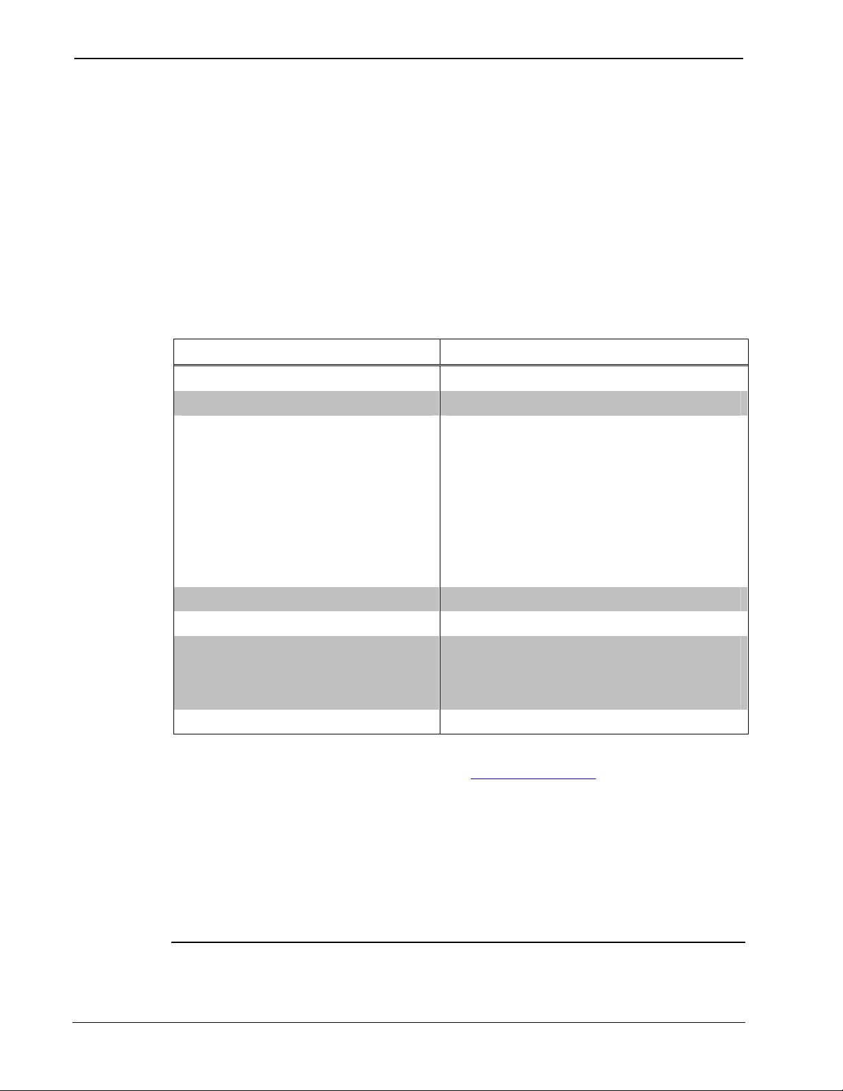
Specifications for the Shade Controller
SPECIFICATION DETAILS
Cresnet power usage 1 Watt (42 mAmp @ 24 VDC)
Default Net ID 0C
Control System Update Files1
2-Series Control System
CEN/CN-TVAV
CNMSX-AV/Pro
CNRACKX/-DP
CNMS, CNRACK, CNLCOMP
ST-CP
Operating Temperature 41° to 122°F (5° to 50°C)
Humidity 10% to 90% RH (non-condensing)
Overall Dimensions Width: 2.14 in (5.44 cm)
Weight 0.25 lb (0.11 kg)
1. The latest software versions can be obtained from the Downloads | Software
Updates section of the Crestron website (www.crestron.com
following these footnotes.
2. Crestron 2-Series control systems include the AV2 and PRO2. Consult the latest
Crestron Product Catalog for a complete list of 2-Series control systems.
Version C2-2004.CUZ or later2
Version 5.13.12V.UPZ or later3
Version 5.12.63X.UPZ or later3
Version 5.10.11W.UPZ or later3
Version 3.18.09m, l, c or later
Version 4.02.04S.UPZ or later3
Height: 0.94 in (2.39 cm)
Depth: 3.83 in (9.73 cm)
). Refer to the NOTE
3. Filenames for CNX and ST-CP update files have a UPZ extension. Files on the
website may be .zip or self-extracting .exe files containing the .cuz or .upz file. To
avoid program problems, make sure you are using the update file with the correct
suffix letter (e.g., S, V, W, X).
NOTE: Crestron software and any files on the website are for Authorized
Crestron dealers and Crestron Authorized Independent Programmers
2 • ILT Shade Controller: C2N-SSC-2 Operations & Installation Guide - DOC. 6318
Page 7
Crestron C2N-SSC-2 ILT Shade Controller
(CAIP) only. New users may be required to register to obtain access to
certain areas of the site (including the FTP site).
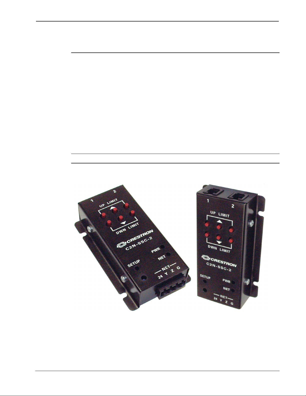
Physical Description
Refer to the figures below and on the following page. The unit is housed
in a black metal enclosure with labeling and controls on the front surface.
The bottom edges of the cover/faceplate extend to form two flanges with
screw slots for convenient mounting on any flat surface. Interface
connectors are mounted on opposite ends of the unit. The two 4-pin
RJ-11 connectors on the “top” end, labeled 1 and 2, provide connection
to two shade motor controller circuits. A 4-pin male Cresnet network port
on the “bottom” end, labeled 24 Y Z G, provides operating power and
communications to/from the unit.
NOTE: Power for the shade motor is independent of the Cresnet system.
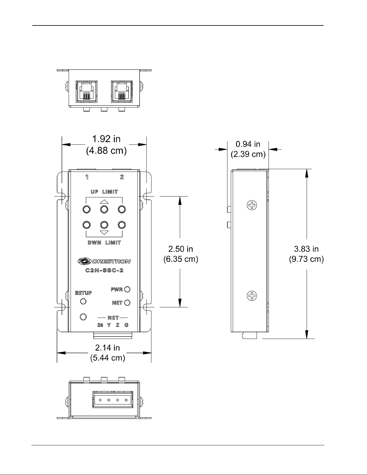
Physical Views
Operations & Installation Guide - DOC. 6318 ILT Shade Controller: C2N-SSC-2 • 3
Page 8
ILT Shade Controller Crestron C2N-SSC-2
Physical Views (continued)
4 • ILT Shade Controller: C2N-SSC-2 Operations & Installation Guide - DOC. 6318
Page 9
Crestron C2N-SSC-2 ILT Shade Controller
Controls
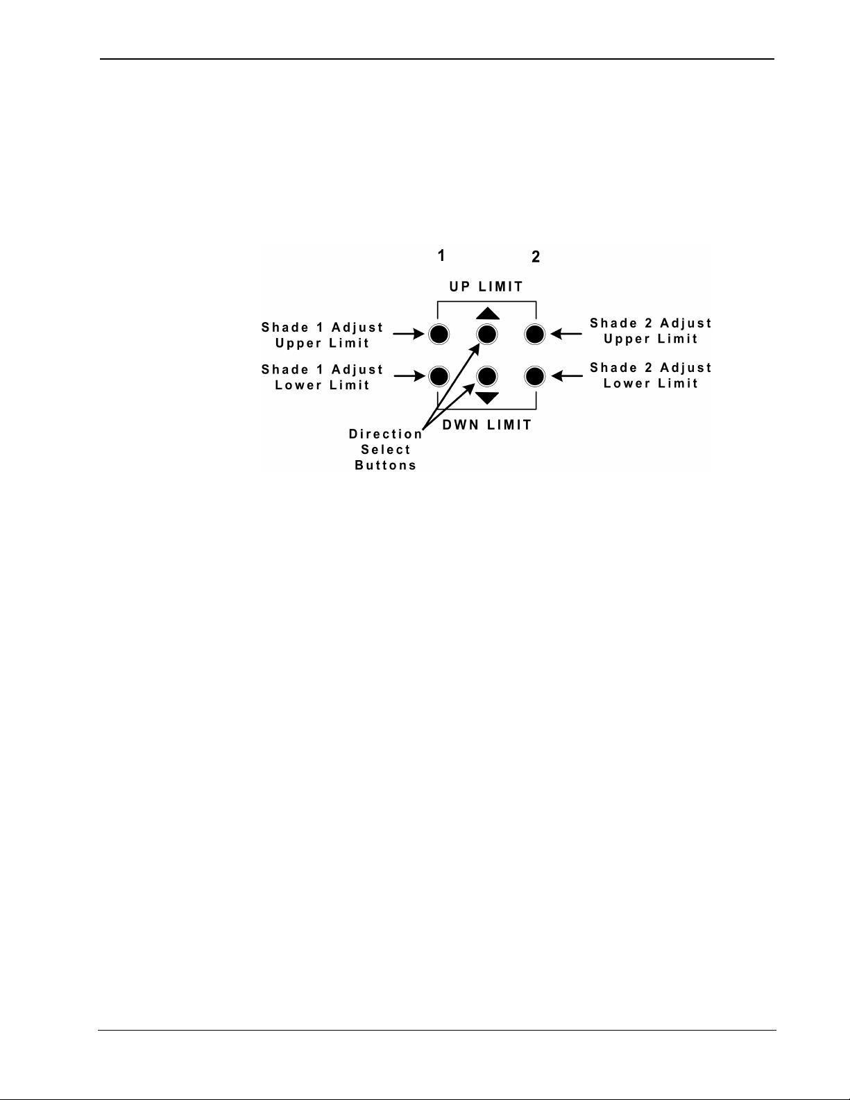
The Shade Controller has six pushbuttons that are used to set the upper
and lower limits of travel for each shade. These limits are set at time of
installation and the values are stored in the ILT motor.
Shade Limit Control Pushbuttons
Pressing any one of the four outer pushbuttons puts the Shade Controller
into the limit-setting mode for the selected shade and upper or lower
limit. (Refer to “Setting Shade Limits and Direction of Travel” on page
13.)
Indicators
The only indicators on the Shade Controller are the three LEDs on the
face of the unit.
• The PWR LED (green) indicates the presence of +24V Cresnet
power.
• The NET LED (yellow) indicates an active Cresnet network
connection.
• The SETUP LED (red) indicates firmware upgrade, limit
setting, shade reversal, or the unit’s network ID setup activity.
− Flashes during firmware downloads
− On solid if in firmware loader mode (still needs application
firmware). Turns off after application firmware is loaded.
− On solid for twenty seconds if a shade 1/2 adjust
upper/lower limit button is pushed, putting the unit into
limit-setting mode.
Operations & Installation Guide - DOC. 6318 ILT Shade Controller: C2N-SSC-2 • 5
Page 10

ILT Shade Controller Crestron C2N-SSC-2
− On for one second, then off when shade reversal is executed
from buttons on the unit.
SETUP LED and Pushbutton
The SETUP pushbutton and its associated LED are used for setup of the
unit’s network ID during the initial configuration of a Cresnet system or
when the device is being added/replaced. Refer to “Method B (Touch
Settable IDs)” on page 10 for detailed information.
Industry Compliance
As of the date of manufacture, the Shade Controllers have been tested
and found to comply with specifications for CE marking and standards
per EMC and Radiocommunications Compliance Labelling.
Setup
NOTE: This device complies with part 15 of the FCC rules. Operation is
subject to the following two conditions: (1) this device may not cause
harmful interference, and (2) this device must accept any interference
received, including interference that may cause undesired operation.
Network Wiring
CAUTION: Use only Crestron power supplies for Crestron equipment.
Failure to do so could cause equipment damage or void the Crestron
warranty.
CAUTION: Provide sufficient power to the system. Insufficient power
can lead to unpredictable results or damage to the equipment. Please use
the Crestron Power Calculator to help calculate how much power is
needed for the system.
<http://www.crestron.com/dealer-tech_resources/power_calculator.asp>
NOTE: When installing network wiring, refer to the latest revision of the
wiring diagram(s) appropriate for your specific system configuration,
6 • ILT Shade Controller: C2N-SSC-2 Operations & Installation Guide - DOC. 6318
Page 11

Crestron C2N-SSC-2 ILT Shade Controller
available from the Downloads | Product Manuals | Wiring Diagrams
section of the Crestron website (www.crestron.com)
NOTE: For larger networks (i.e., greater than 28 network devices), it
may be necessary to add a Cresnet Hub/Repeater (CNXHUB) to maintain
signal quality throughout the network. Also, for networks with lengthy
cable runs or varying types of network devices, it may be desirable to add
a hub/repeater after only 20 network devices.
When calculating the wire gauge for a particular Cresnet run, the length
of the run and the Cresnet power usage of each network unit to be
connected must be taken into consideration. If Cresnet units are to be
daisy-chained on the run, the Cresnet power usage of each unit to be
daisy-chained must be added together to determine the Cresnet power
usage of the entire chain. If the unit is a home-run from a Crestron
system power supply network port, the Cresnet power usage of that unit
is the Cresnet power usage of the entire run. The length of the run in feet
and the Cresnet power usage of the run should be used in the following
resistance equation to calculate the value on the right side of the
equation.
.
Resistance Equation
The required wire gauge should be chosen such that the resistance value
is less than the value calculated in the resistance equation. Refer to the
following table.
Wire Gauge Values
RESISTANCE (R) WIRE GAUGE
4
6
10
15
13
8.7
Doubled CAT5
16
18
20
22
Tripled CAT5
Operations & Installation Guide - DOC. 6318 ILT Shade Controller: C2N-SSC-2 • 7
Page 12

ILT Shade Controller Crestron C2N-SSC-2
f
NOTE: All Cresnet wiring must consist of two twisted pairs. One twisted
pair is the +24V conductor and the GND conductor, and the other twisted
pair is the Y conductor and the Z conductor.
NOTE: When daisy-chaining Cresnet units, strip the ends of the wires
carefully to avoid nicking the conductors. Twist together the ends of the
wires that share a pin on the network connector, and tin the twisted
connection. Apply solder only to the ends of the twisted wires. Avoid
tinning too far up the wires or the end becomes brittle. Insert the tinned
connection into the Cresnet connector and tighten the retaining screw.
Repeat the procedure for the other three conductors.
Identity Code
Every equipment and user interface within the network requires a unique
identity code (Cresnet ID or Net ID). These codes are two-digit
hexadecimal numbers from 03 to FE. The Net ID of each unit must match
an ID code specified in the SIMPL Windows program. Refer to “Setting
the Net ID in Device Settings” on page 20 for details of the SIMPL
Windows procedure.
Refer to note
on page 27
or a
definition of
Viewport.
The Net ID of the C2N-SSC-2 has been factory set to 0C. The Net IDs of
multiple Shade Controllers in the same system must be unique. Net IDs are
changed from a personal computer (PC) via the Crestron Viewport.
NOTE: For detailed information on establishing communication between
the PC and control system, refer to “Communication Settings” on page
27. If communication cannot be established, refer to the
“Troubleshooting Communications” section in the latest version of the
2-Series Control System Reference Guide (Doc. 6256), which is
available from the Downloads | Product Manuals section of the Crestron
website (www.crestron.com). For other control systems, refer to the
respective Operations Guide.
There are two different methods—Method A or Method B—for setting
the Shade Controller Net IDs:
Method A (Cresnet address-settable ID), described on the next page,
applies to all Shade Controllers in a Cresnet system. This method
8 • ILT Shade Controller: C2N-SSC-2 Operations & Installation Guide - DOC. 6318
Page 13

Crestron C2N-SSC-2 ILT Shade Controller
requires that a single Shade Controller be the only network device
connected to the control system.
Method B (Touch Settable IDs), which begins on page 10, applies to
Shade Controllers in a Cresnet system with 2-Series control system
upgrade file (CUZ) version 3.008 or later. These upgrades enable Touch
Settable ID (TSID) functionality, which makes it possible for the control
system to recognize a network device via its serial number, which is
stored in the device’s memory. This method does not require that any
devices be disconnected from the network; Net IDs may be set with the
entire Cresnet system intact.
Use the appropriate method to set the Shade Controller Net ID.
Method A (Cresnet address-settable ID)
1. Ensure that the Shade Controller is the only device connected
to the control system.
2. Open the Crestron Viewport.
3. From the Viewport menu, select Functions | Set Network ID.
The software checks the baud rate and then opens the "Set
Network ID" window.
4. In the "Set Network ID" window, select the C2N-SSC-2 from
the Current Network Devices text window.
5. Select the new Net ID for the Shade Controller from the
Choose the new network ID for the selected device (Hex): text
box.
6. Click Set ID to initiate the change. This will display the "ID
command has been sent" window.
7. In the "Command Complete" window, click OK.
8. In the Current Network Devices text window, verify the new
Net ID code.
9. In the "Set Network ID" window, click Close.
NOTE: The new Net ID code may also be verified by selecting
Diagnostics | Report Network Devices in the Viewport (alternately,
select F4).
10. Repeat this procedure for each Shade Controller to be added
to the system.
Operations & Installation Guide - DOC. 6318 ILT Shade Controller: C2N-SSC-2 • 9
Page 14

ILT Shade Controller Crestron C2N-SSC-2
Method B (Touch Settable IDs)
Before using this method, you should have a list of all current network
devices and their Net IDs, to avoid assigning duplicate IDs.
Set Net ID via D3 Pro or SystemBuilder
Version 1.0 of this program includes procedures that enable setting the
Net ID. Refer to the extensive help information provided with the
software file for instructions. (For a brief description of the D3 Pro
program, refer to “Programming with Crestron SystemBuilder or D3 Pro”
on page 18.)
Set Net ID by TSID
These procedures are for TSID-enabled network devices during the initial
configuration of a Cresnet system or when such devices are being
added/replaced.
1. Ensure that all Shade Controllers are connected to the control
system.
2. Open the Crestron Viewport version 3.35 or later.
3. From the Viewport menu, select Functions | Assign Cresnet
ID by Serial Number. The “Set Net ID by TSID” window
appears. The window is first displayed with the data fields
empty.
• When you click on the Search for Touch Settable
Devices button, the system searches the network and lists
all TSID-enabled devices found, as shown in the figure on
the next page.
• This information is similar to the report produced by
pressing F4 (Report Network Devices); the first eight
digits of each line constitute the TSID number
(hexadecimal form of the serial number).
10 • ILT Shade Controller: C2N-SSC-2 Operations & Installation Guide - DOC. 6318
Page 15

Crestron C2N-SSC-2 ILT Shade Controller
“Set Net ID by TSID” Window
4. As you enter either the serial number or TSID number of the
device that requires a change, the corresponding TSID or
serial number automatically appears in its appropriate field.
The listing should show the device’s current Cresnet ID.
CAUTION: This function does not prevent you from setting duplicate
IDs. Be sure to check current assignments before entering the desired
Cresnet ID number.
5. Enter the Cresnet ID that the device should be set to and click
OK.
Serial Number to TSID Conversion
This utility is useful in a case where there are multiple devices of the
same type on a network, you need to locate a particular one, you know
the TSID but not the serial number, and your site installation list is based
on device serial numbers. In this (or the reverse) situation, perform the
procedures given on the following page.
Operations & Installation Guide - DOC. 6318 ILT Shade Controller: C2N-SSC-2 • 11
Page 16

ILT Shade Controller Crestron C2N-SSC-2
1. Open the Crestron Viewport.
2. From the Viewport menu, select Functions | Serial Number
ÅÆ TSID Conversion Tool. The “Serial Number ÅÆTSID
Conversion Tool” window is displayed.
“Serial Number to TSID Conversion Tool” Window
3. Enter the serial number or TSID number as instructed; press
the appropriate button to obtain the corresponding number.
NOTE: Enter serial numbers, including spaces, exactly as they appear on
the unit label. Alpha characters in serial numbers or TSID numbers may
be entered in upper or lower case.
Installation
The following tools/hardware are required for installation of the Shade
Controller:
• Cresnet network cable (not supplied)
• Cresnet 4-pin mating connector (supplied)
• Dual Lock fastener (supplied)
• Phillips screwdriver (not supplied)
• Four 1 in. #6 pan head Phillips screws (not supplied)
NOTE: Verify that you have sufficient Cresnet power to support your
net devices.
12 • ILT Shade Controller: C2N-SSC-2 Operations & Installation Guide - DOC. 6318
Page 17

Crestron C2N-SSC-2 ILT Shade Controller
Overview
Installation consists of mounting the Shade Controller (using either the
Dual Lock fastener or screws, as desired) in a location that is out of
casual reach, but within fifty feet of the shade(s) it controls; connecting a
Cresnet cable to the NET port; connecting the interface cable(s) from the
shade(s) to the RJ-11 port(s), and setting the upper and lower limits of
travel for the shade(s).
1. Turn Cresnet system power OFF.
2. Connect the Cresnet cable with supplied mate to the Shade
Controller’s Cresnet port and the other end to the control
system.
3. Connect the modular cable from the shade(s) to the Shade
Controller RJ-11 port(s). If a longer modular cable is required,
fabricate using standard 4-wire modular cable with 4-pin
(4 body size) modular plugs.
− Invert the plugs on the same cable. When the plugs are
held side by side, the wires are in the same order (refer to
following graphic).
− Check that the connector is correctly crimped.
Setting Shade Limits and Direction of Travel
When an ILT shade is first installed, the limits of travel will normally
come “pinched” together so that the shade will not move up or down.
Limits and travel direction for an ILT shade are not set mechanically, but
are stored electronically in the shade motor itself. Limits of travel must
be set for each shade in order for the shade to operate properly. The six
Operations & Installation Guide - DOC. 6318 ILT Shade Controller: C2N-SSC-2 • 13
Page 18

ILT Shade Controller Crestron C2N-SSC-2
buttons on the Shade Controller are used to set these limits, as defined in
the following table. Shade limits can also be set using the C2N-SSC-2
symbol.
Shade Limit Control Pushbutton Functions
Shade 1 Adjust
Upper Limit Button
Shade 1 Adjust
Lower Limit Button
Shade 2 Adjust
Upper Limit Button
Shade 2 Adjust
Lower Limit Button
Up Button (K) In limit-setting mode, moves shade up; sets limit on
Down Button (J) In limit-setting mode, moves shade down; sets limit on
Push to allow adjustment of Shade 1 upper limit.
SETUP LED will be on during limit-setting mode.
Push and hold for five seconds to open to upper limit.
Push to allow adjustment of Shade 1 lower limit.
SETUP LED will be on during limit-setting mode.
Push and hold for five seconds to close to lower limit
Push to allow adjustment of Shade 2 upper limit.
SETUP LED will be on during limit-setting mode.
Push and hold for five seconds to open to upper limit.
Push to allow adjustment of Shade 2 lower limit.
SETUP LED will be on during limit-setting mode.
Push and hold for five seconds to close to lower limit
release.
When not in limit-setting mode, hold button down for 10
seconds to reverse Shade 1 orientation. SETUP LED
gives confirming flash when reversal is executed.
release.
When not in limit-setting mode, hold button down for 10
seconds to reverse Shade 2 orientation. SETUP LED
gives confirming flash when reversal is executed.
To prevent inadvertent setting of very wide limits, continuous adjustment
is allowed for periods of twenty seconds. At the end of any 20 second
period, the limit-setting mode will automatically terminate, and an adjust
limit select button must be pushed to initiate additional limit settings. For
example, if an adjust limit select button is pressed and no other buttons
are pushed, the Shade Controller will remain in limit-setting mode for
twenty seconds. At the end of this period, the SETUP LED will go off to
indicate that limits are no longer ready to be adjusted. Similarly, if limits
are being adjusted and the up (K) or down (j) button is pushed and
held, the shade will stop moving after 20 seconds and the limit-setting
mode will be terminated. Pushing any of the six buttons during the
20-second limit period will start a new 20-second period.
NOTE: Set the upper limit before setting the lower limit.
14 • ILT Shade Controller: C2N-SSC-2 Operations & Installation Guide - DOC. 6318
Page 19

Crestron C2N-SSC-2 ILT Shade Controller
NOTE: During the limit-setting procedures, if the shade moves opposite
to the selected direction, refer to the direction reversing procedures given
on the next page.
NOTE: Perform limit or travel direction settings for each shade
individually.
NOTE: Do not press other buttons or touchpanel controls while setting
shade limits. Doing so will terminate the limit-setting procedure.
The following procedures apply to either shade. It is not necessary to set
the limits for shade 1 before shade 2.
Setting Shade 1 Upper Limit:
Press the shade 1 adjust upper limit button. The SETUP LED should
illuminate. The Shade Controller is now ready to set the upper limit of
travel for shade 1. Use the up (K) and down (j) buttons to adjust the
upper limit position. The shade will roll in the direction selected until the
button is released or the 20-second, limit-setting period ends. Upon
release of the button, the upper limit of travel will be stored in the ILT
shade. If necessary, repeat the procedure until the shade is correctly
positioned.
Setting Shade 1 Lower Limit:
Press the shade 1 adjust lower limit button for shade 1. The SETUP LED
should illuminate. The Shade Controller is now ready to set the lower
limit of travel for shade 1. Use the up (K) and down (j) buttons to
adjust the lower limit position. The shade will roll in the direction
selected until the button is released. Upon release of the button, the lower
limit of travel will be stored in the ILT shade. If necessary, repeat the
procedure until the shade is correctly positioned.
Limit-setting Verification:
It is recommended that both the upper and lower limits be verified after
the initial setup. First, verify that the shade is not in limit-setting mode by
confirming that the SETUP LED is not on. Push and hold the shade 1
adjust upper limit button for at least five seconds. Shade 1 will roll and
stop at the upper limit of travel. Push and hold the shade 1 adjust lower
limit button for at least five seconds. Shade 1 will roll and stop at the
lower limit of travel.
Operations & Installation Guide - DOC. 6318 ILT Shade Controller: C2N-SSC-2 • 15
Page 20

ILT Shade Controller Crestron C2N-SSC-2
Reversing the Direction of Travel for a Shade
Whether a shade rolls up or down when a particular button is pushed
depends on the orientation of the shade during installation as well as how
the shade material is mounted to the cylinder. If the installer finds that the
shade moves opposite to the direction required, the direction of travel can
be reversed as follows:
For shade 1, verify that the unit is not in limit-setting mode (SETUP LED
is not illuminated), and then press and hold the up (K) button for at least
10 seconds. The SETUP LED will give a confirming flash. The direction
of travel for shade 1 has now been reversed.
For shade 2, verify that the unit is not in limit-setting mode (SETUP LED
is not illuminated), and then press and hold the down (j) button for at
least 10 seconds. The SETUP LED will give a confirming flash. The
direction of travel for shade 2 has now been reversed.
NOTE: Perform shade reversals on one shade at a time.
NOTE: After a reversal, it is necessary to re-adjust the limits since the
reversal process again pinches the upper and lower limits together so that
the shade cannot move.
Programming Software
Have a question or comment about Crestron software?
Answers to frequently asked questions (FAQs) can be viewed in the
Online Help section of the Crestron website (www.crestron.com). Log in
at http://www.crestron.com/accounts/login.asp
or view questions you have submitted to Crestron’s True Blue Support.
First-time users will need to establish a user account.
to post your own question
16 • ILT Shade Controller: C2N-SSC-2 Operations & Installation Guide - DOC. 6318
Page 21

Crestron C2N-SSC-2 ILT Shade Controller
You can create a program that allows you to set up the C2N-SSC-2 to
operate in a Crestron control system using the Crestron programming
tools: Crestron System Builder
™
, D3 Pro™ (for lighting and HVAC) and
SIMPL Windows. These tools are intended for users with different levels
of programming knowledge. The flexibility of each tool is proportional to
the degree of programming expertise (i.e., the more flexible, the more a
programmer needs to know and account for). Of course, one can initiate
programming using the easiest method (System Builder) and use
advanced techniques that are available from SIMPL Windows to
customize the job.
The program output of Crestron SystemBuilder is a SIMPL Windows
program with much of the functionality encapsulated in macros and
templates. Therefore, extending the capabilities of the system is very
easy. Crestron SystemBuilder is easier to use for the beginning
programmer, and much faster for all programmers. However, it does not
allow the degree of control and flexibility that SIMPL Windows does.
Crestron SystemBuilder comes with templates for all supported
interfaces. If a user wishes to create a touchpanel project using templates
with a different look-and-feel, this can be accomplished by making a
custom template. This custom template can then be used by Crestron
SystemBuilder to create the final project files to be loaded into the
panels. Alternatively, VT Pro-e can be used to tweak projects created
with the Crestron SystemBuilder or develop original touchpanel screen
designs.
NOTE: Crestron recommends that you use the latest software to take
advantage of the most recently released features. The latest software is
available from the Downloads | Software Updates section of the Crestron
website (www.crestron.com).
The following are the earliest useable software version requirements for
the PC:
• (Optional) SystemBuilder version 2.0 or later.
• (Optional) D3 Pro version 1.3.7 or later.
• SIMPL Windows version 2.05.22 or later, with Library Update
file 311. Requires SIMPL+
®
Cross Compiler version 1.1.
• Crestron Database version 16.4 or later.
Operations & Installation Guide - DOC. 6318 ILT Shade Controller: C2N-SSC-2 • 17
Page 22

ILT Shade Controller Crestron C2N-SSC-2
p
f
Programming with Crestron SystemBuilder or D3 Pro
The easiest
method of
rogramming,
but does not
offer as much
lexibility
as SIMPL
Windows.
Crestron SystemBuilder offers automatic programming for such
residential and commercial applications as audio distribution, home
theater, video conferencing, and lighting. The interface of this tool guides
you through a few basic steps for designating rooms and specifying the
control system, touchpanels, devices, and functionality. Crestron
SystemBuilder then programs the system, including all touchpanel
projects and control system logic.
Crestron D3 Pro similarly offers automatic programming for lighting and
HVAC projects.
Both Crestron SystemBuilder and D3 Pro integrate fully with Crestron's
suite of software development tools, including SIMPL Windows, VT
Pro-e, and the Crestron Database. Both access these tools behind the
scenes, enabling you to easily create robust systems.
Programming with SIMPL Windows
NOTE: The following are acceptable file extensions for programs that
include a C2N-SSC-2, developed for specific control system types:
.smw projectname.smw (source file)
.spz projectname.spz (compiled file for 2-series)
.bin projectname.bin (compiled file for CNX generation)
.csz projectname.csz (compiled file for CNX generation with
SIMPL+)
.ush projectname.ush (compiled file for CNX generation with
SIMPL+ header file)
.usp projectname.usp (source code module for SIMPL+
NOTE: The following assumes that the reader has knowledge of SIMPL
Windows. If not, refer to the extensive help information provided with
the software.
NOTE: In the following description, the PRO2 control system is used.
SIMPL Windows is Crestron's software for programming Crestron
control systems. It provides a well-designed graphical environment with
a number of workspaces (i.e., windows) in which a programmer can
select, configure, program, test, and monitor a Crestron control system.
18 • ILT Shade Controller: C2N-SSC-2 Operations & Installation Guide - DOC. 6318
Page 23

Crestron C2N-SSC-2 ILT Shade Controller
SIMPL Windows offers drag and drop functionality in a familiar
Windows
This section explains how to create a SIMPL Windows program that
includes a Shade Controller.
Configuration Manager is where programmers “build” a Crestron control
system by selecting hardware from the Device Library. In Configuration
Manager, drag the PRO2 from the Control Systems folder of the Device
Library and drop it in the upper pane of the System Views. The PRO2
with its associated communication ports is displayed in the System Views
upper pane.
PRO2 System View
environment.
The System Views lower pane displays the PRO2 system tree. This tree
can be expanded to display and configure the communications ports.
Expanded PRO2 System Tree
C2Net-Device Slot in Configuration Manager
To incorporate a Shade Controller into the system, drag the C2N-SSC-2
from the Cresnet Control Modules | Cresnet Shade/Drape Controllers
folder of the Device Library and drop it in System Views. The PRO2
Operations & Installation Guide - DOC. 6318 ILT Shade Controller: C2N-SSC-2 • 19
Page 24

ILT Shade Controller Crestron C2N-SSC-2
system tree displays the C2N-SSC-2 in Slot 9, with a default Net ID of
0C as shown in the following illustration.
NOTE: The first C2N-SSC-2 in a system is preset with a Net ID of 0C
when its symbol is dragged into the upper pane of System Views.
Additional units are assigned different Net ID numbers as they are added.
C2Net Device, Slot 9
Setting the Net ID in Device Settings
Double-click the C2N-SSC-2 icon in the upper pane to open the “Device
Settings” window. This window displays C2N-SSC-2 device
information. The Net ID can be changed in this window using the Net ID
tab, as shown in the following figure.
20 • ILT Shade Controller: C2N-SSC-2 Operations & Installation Guide - DOC. 6318
Page 25

Crestron C2N-SSC-2 ILT Shade Controller
“C2N-SSC-2 Device Settings” Window
NOTE: This procedure sets the Net ID for the C2N-SSC-2 in the
program only. It does not automatically set the Net ID for the Shade
Controller itself.
NOTE: SIMPL Windows automatically changes Net ID values of a
device added to a program if a duplicate device or a device with the same
Net ID already exists in the program. Always ensure that the hardware
and software settings of the Net ID match. For Net ID hardware setting
details, refer to “Identity Code” on page 8.
C2N-SSC-2 Symbol in Programming Manager
Programming Manager is where programmers “program” a Creston
control system by assigning signals to symbols. The graphics on the next
pages show the C2N-SSC-2 symbol in the SIMPL Windows
Programming Manager.
Operations & Installation Guide - DOC. 6318 ILT Shade Controller: C2N-SSC-2 • 21
Page 26

ILT Shade Controller Crestron C2N-SSC-2
C2N-SSC-2 Symbol in SIMPL Windows Programming Manager
22 • ILT Shade Controller: C2N-SSC-2 Operations & Installation Guide - DOC. 6318
Page 27

Crestron C2N-SSC-2 ILT Shade Controller
The following table lists the symbol input and output signals and their
functional descriptions. The table lists the signals and descriptions for
shade 1 (Sh1); the same signals repeat for shade 2 (Sh2).
C2N-SSC-2 Symbol Signal Descriptions
Signal Type & Name Description
Opens Shade 1 toward the upper limit of travel
Digital input:
<Sh1_OpenMomentary>
Digital input:
<Sh1_CloseMomentary>
on the rising edge of the input, and stops on
release.
High/1 (rising edge) = Open;
Low/0 (falling edge) = Stop
Closes Shade 1 toward the lower limit of travel
on the rising edge of the input, and stops on
release.
High/1 (rising edge) = Close;
Low/0 (falling edge) = Stop
Digital input:
<Sh1_OpenFull>
Digital input:
<Sh1_CloseFull>
Digital input:
<Sh1_Stop>
Digital input:
<Sh1_OpenJog>
Digital input:
<Sh1_CloseJog>
Opens Shade 1 to the upper limit of travel on
the rising edge of the input.
High/1 (rising edge) = Open full;
Low/0 = No effect
Closes Shade 1 to the lower limit of travel on
the rising edge of the input.
High/1 (rising edge) = Close full;
Low/0 = No effect
Stops Shade 1 movement on the rising edge
of the input.
High/1 (rising edge) = Stop;
Low/0 = No effect
Opens Shade 1 toward the upper limit of travel
for <Sh1_JogTime> seconds, on the rising
edge of the input.
High/1 (rising edge) = Jog open;
Low/0 = No effect
Closes Shade 1 toward the lower limit of travel
for <Sh1_JogTime> seconds, on the rising
edge of the input.
High/1 (rising edge) = Jog close;
Low/0 = No effect
(continued on next page)
Operations & Installation Guide - DOC. 6318 ILT Shade Controller: C2N-SSC-2 • 23
Page 28
ILT Shade Controller Crestron C2N-SSC-2
C2N-SSC-2 Symbol Signal Descriptions (continued)
Signal Type & Name Description
Indicates that Shade 1 is moving. The output
remains high while the shade is moving.
Digital output:
<Sh1_Moving>
Digital output:
<Sh1_LastDirOpen>
Digital output:
<Sh1_LastDirClose>
This does not apply in limit-setting mode.
Note: Adjusting the upper or lower limit has no
effect on the state of the output.
High/1 = Shade 1 moving;
Low/0 = Shade 1 stopped
Indicates that the current direction of movement
is toward the upper limit. If not currently moving,
indicates that the previous direction of
movement was toward the upper limit.
This does not apply in limit-setting mode.
Note: Adjusting the upper or lower limit has no
effect on the state of the output.
High/1 = Last direction open;
Low/0 = Last direction not open
Indicates that the current direction of movement
is toward the lower limit. If not currently moving,
indicates that the previous direction of
movement was toward the lower limit.
This does not apply in limit-setting mode.
Note: Adjusting the upper or lower limit has no
effect on the state of the output.
High/1 (rising edge) = Last direction close;
Low/0 = Last direction not close.
Stores the current position of Shade 1 to the
preset number given by <Sh1_Preset#>, on the
Digital input:
<Sh1_SetPreset>
Digital input:
<Sh1_RecallPreset>
rising edge of the input.
input has no effect if preset number is invalid.
High/1 (rising edge) = Save preset;
Low/0 = No effect
Moves Shade 1 to the preset position given by
<Sh1_Preset#>, on rising edge of the input.
The input has no effect if the preset number is
invalid, or if the preset has no position stored.
High/1 (rising edge) = Recall preset;
Low/0 = No effect
(continued on next page)
24 • ILT Shade Controller: C2N-SSC-2 Operations & Installation Guide - DOC. 6318
Page 29

Crestron C2N-SSC-2 ILT Shade Controller
C2N-SSC-2 Symbol Signal Descriptions (continued)
Signal Type & Name Description
Reports the position of Shade 1 (via
<Sh1_PosReport>) with each rising edge of
the input.
Digital input:
<Sh1_ReportPos>
Digital input:
<Sh1_UpperLimUp>
Digital input:
<Sh1_UpperLimDn>
Digital input:
<Sh1_LowerLimUp>
Digital input:
<Sh1_LowerLimDn>
Digital input:
<Sh1_Reverse>
Subsequent changes in position are reported
for as long as the input remains high.
High/1 (rising edge and level sensitive) =
Report position;
Low/0 = Disable reporting
Opens Shade 1 while the input is high, and
sets the upper travel limit on release.
Turns on SETUP LED for 20 seconds.
High/1(level sensitive) = Shade up;
Low/0 (falling edge) = Stop and set upper limit
Closes Shade 1 while the input is high, and
sets the upper travel limit on release.
Turns on SETUP LED for 20 seconds.
High/1 (level sensitive) = Close shade;
Low/0 (falling edge) = Stop and set upper limit
Opens Shade 1 while the input is high, and
sets the lower travel limit on release.
Turns on SETUP LED for 20 seconds.
High/1 (level sensitive) = Shade up;
Low/0 (falling edge) = Stop and set lower limit
Closes Shade 1 while the input is high, and
sets the lower travel limit on release.
Turns on SETUP LED for 20 seconds.
High/1 (level sensitive) = Shade down;
Low/0 (falling edge) = Stop and set lower limit
Reverses motor direction on the rising edge of
the input.
Reversing direction sets the upper and lower
limits to the current shade position, resulting in
no movement if a position input is asserted.
Therefore, upper and lower limits must be
reset after the reverse command is triggered.
For most applications, reverse command is set
only once, if necessary, during installation.
High/1 (rising edge) = Reverse motor rotation;
Low/0 = No effect
(continued on next page)
Operations & Installation Guide - DOC. 6318 ILT Shade Controller: C2N-SSC-2 • 25
Page 30

ILT Shade Controller Crestron C2N-SSC-2
C2N-SSC-2 Symbol Signal Descriptions (continued)
Signal Type & Name Description
Sets the preset number for which a position
will be saved (on the rising edge of
<Sh1_SetPreset>) or recalled (on the rising
Analog input:
<Sh1_Preset#>
edge of <Sh1_RecallPreset>).
Valid values range from 1d to 20d.
Out of range values will cause the save and
recall inputs to have no effect.
Sets Shade 1 position relative to the full range
of travel between the upper and lower limits.
Valid values range from 0d to 65,535d, which
is 0000h to FFFFh (upper limit).
Analog input:
<Sh1_Position>
Analog output:
<Sh1_PosReport>
Analog input:
<Sh1_JogTime>
Note: Only the most significant bits affect the
position.
0000h = No movement.
00xxh (where xx is any value between 01 and
FF) = Lower limit.
FFxxh (where xx is any value between 100
and FF) = Upper limit.
Reports the position of Shade 1 on the rising
edge of <Sh1_ReportPos>, and all
subsequent changes in position for as long as
<Sh1_ReportPos> is high.
Reported values range from 0d to 65,535d,
which is 0000h to FFFFh (upper limit).
Note: Only the most significant bits are
recognized position changes.
Defines the period that Shade 1 will jog open
or jog closed.
Valid values range from 0.05s (0.05 seconds)
to 2s (2 seconds).
Values above 2s will set the jog time to 2
seconds; values below 0.05s will set the jog
time to 0.05s.
Example Program
An example program for the Shade Controller is available from the
"Example Programs" section of the Crestron website
(http://www.crestron.com/exampleprograms
26 • ILT Shade Controller: C2N-SSC-2 Operations & Installation Guide - DOC. 6318
). Search for C2N-SSC-2.zip.
Page 31

Crestron C2N-SSC-2 ILT Shade Controller
Uploading and Upgrading
Assuming a PC is properly connected to the entire system, Crestron
programming software allows the programmer to upload programs and
projects to the system and touchpanel and firmware to the Shade
Controllers after their development. However, there are times when the
files for the program and projects are compiled and not uploaded.
Instead, compiled files may be distributed from programmers to
installers, from Crestron to dealers, etc. Even firmware upgrades are
available from the Crestron website as new features are developed after
product releases. In those instances, one has the option to upload via the
programming software or to upload and upgrade via the Crestron
Viewport.
NOTE: The Crestron Viewport is available as a pull-down command
from SIMPL Windows and VT Pro-e (Tools | Viewport), or as a
standalone utility. The Viewport utility accomplishes multiple system
tasks, primarily via an RS-232 or TCP/IP connection between the control
system and a PC. It is used to observe system processes, upload new
operating systems and firmware, change system and network parameters,
and communicate with network device consoles and touchpanels, among
many other tasks. Viewport can also function as a terminal emulator for
generic file transfer. All of these functions are accessed through the
commands and options in the Viewport menus. Therefore, for its
effectiveness as a support and diagnostic tool, the Crestron Viewport may
be preferred over development tools when uploading programs and
projects.
The following sections define how one would upload a SIMPL Windows
program, or upgrade the firmware of the C2N-SSC-2. However, before
attempting to upload or upgrade, it is necessary to establish
communications.
Communication Settings
NOTE: For laptops and other PCs without a built-in RS-232 port,
Crestron recommends the use of PCMCIA cards, rather than USB-toserial adapters.
Operations & Installation Guide - DOC. 6318 ILT Shade Controller: C2N-SSC-2 • 27
Page 32

ILT Shade Controller Crestron C2N-SSC-2
If a USB-to-serial adapter must be used, Crestron has tested the following
devices with good results.
Belkin (large model) F5U103
I/O Gear GUC232A (discontinued)
Keyspan USA-19QW (discontinued)
Other models, even from the same manufacturer, may not yield the same
results.
The procedure in this section provides details for RS-232 communication
between the PC and the control system. If TCP/IP communication is
preferred, consult the latest version of the Crestron e-Control Reference
Guide (Doc. 6052) or the respective Operations Guide for the control
system. These documents are available from the Downloads | Product
Manuals section of the Crestron website (www.crestron.com). Refer to
the figure below for a typical connection diagram when uploading files.
Note: Use a standard DB9 male to female “straight-through” cable.
Typical Connection Diagram when Uploading
28 • ILT Shade Controller: C2N-SSC-2 Operations & Installation Guide - DOC. 6318
Page 33

Crestron C2N-SSC-2 ILT Shade Controller
1. Open the Crestron Viewport.
Either launch the stand-alone version of Viewport, or start
SIMPL Windows and from the menu bar, select Tools |
Viewport.
2. Refer to the figure after this step. From the Viewport menu,
select Setup | Communications settings (alternatively, press
Alt+D) to open the “Port Settings” window.
Setup | Communications Settings Command
3. Select RS-232 as the connection type. Verify that an available
COM port (COM 1 is shown after this step) is selected, and
that all communication parameters and necessary options
from the “Port Settings” window are selected as shown after
this step. Click the OK button to save the settings and close
the window.
Operations & Installation Guide - DOC. 6318 ILT Shade Controller: C2N-SSC-2 • 29
Page 34

ILT Shade Controller Crestron C2N-SSC-2
“Port Settings” Window
NOTE: The parameters shown in the illustration above are the port
settings for a 2-Series control system. Consult the Operations Guide for
the control system being used for exact parameter selection.
4. To verify communication, select Diagnostics | Establish
Communications (Find Rack). This should display a
window that gives the COM port and baud rate. If
communication cannot be established, refer to the
“Troubleshooting Communications” section in the latest
version of the Crestron 2-Series Control Systems Reference
Guide (Doc. 6256) or the respective Operations Guide for the
control system.
30 • ILT Shade Controller: C2N-SSC-2 Operations & Installation Guide - DOC. 6318
Page 35

Crestron C2N-SSC-2 ILT Shade Controller
f
Uploading a SIMPL Windows Program
A control
system
source file
has the
extension
.smw. A
compiled
SIMPL
Windows file
has the
extension
.spz for a 2Series
control
system, .bin
or CNX
generation,
and .csz for
CNX
generation
with
SIMPL+.
The SIMPL Windows file can be uploaded to the control system using
SIMPL Windows or via the Crestron Viewport.
Upload via SIMPL Windows
1. Start SIMPL Windows.
2. Select File | Open to view the “Open” window,
navigate to the SIMPL Window file (.smw),
and click Open.
3. Select Project | Transfer Program.
Upload via Crestron Viewport
1. Verify that the procedure for “Communication Settings” that
begins on page 27 has been performed.
2. As shown after this step, select File Transfer | Send
Program (alternatively, press Alt+P) from the Viewport
menu bar.
File Transfer | Send Program Command
3. The “Send Program” window appears, as shown on the next
page. Click Browse, locate the compiled file (.spz for PRO2)
and click Open. This will display the program's header
information and enable one or both of the What to Send check
boxes. If the program does not contain any SIMPL+ modules,
only the SIMPL Program check box will be enabled. If it does
contain SIMPL+ modules, then the SIMPL+ Program(s)
check box will also be enabled. Select one or both check
boxes and then click Send Program to begin the transfer.
NOTE: Refer to the latest version of the Crestron 2-Series Control
Systems Reference Guide (Doc. 6256) or the respective Operations
Operations & Installation Guide - DOC. 6318 ILT Shade Controller: C2N-SSC-2 • 31
Page 36

ILT Shade Controller Crestron C2N-SSC-2
Guide for the control system for details about the other fields shown on
the “Send Program” window.
“Send Program” Window
A firmware
upgrade file
has the
extension
.upg.
4. To verify that the program has been transferred successfully,
select Diagnostics | Report Program Information. This
should display a window that provides details about the
current program loaded into the control system.
Firmware Upgrade
To take advantage of all the C2N-SSC-2 features, it is important that the
unit contains the latest firmware available. Please check the Crestron
website (www.crestron.com/updates
Not every product has a firmware upgrade, but as Crestron improves
functions, adds new features, and extends the capabilities of its products,
firmware upgrades are posted. To upgrade the firmware, complete the
following steps.
1. Make sure that “Communication Settings,” which begins on
page 27, has been performed.
2. As shown after this step, select File Transfer | Update
Network Device Firmware from the Viewport menu bar.
) for the latest version of firmware.
32 • ILT Shade Controller: C2N-SSC-2 Operations & Installation Guide - DOC. 6318
Page 37

Crestron C2N-SSC-2 ILT Shade Controller
File Transfer | Update Network Device Firmware Command
3. As shown in the “Select Network ID” window, select the Net
ID of the C2N-SSC-2, and then click OK. The “Open”
window appears (refer to the graphics below and on the next
page).
“Select Network ID” Window
NOTE: When transferring a Cresnet file (touchpanel project/ firmware),
lower the port speed baud rate to 38400 to match the Cresnet bus speed.
Operations & Installation Guide - DOC. 6318 ILT Shade Controller: C2N-SSC-2 • 33
Page 38

ILT Shade Controller Crestron C2N-SSC-2
“Open” Window
4. Browse to the desired [filename].upg file and click Open to
begin the transfer.
Serial Number Assignment
These procedures are to be used for Shade Controllers that just received a
firmware upgrade enabling TSID support where it was not previously
available.
1. Open the Crestron Viewport.
2. From the Viewport menu, select Functions | Assign Serial
Number. The “Serial Number Assignment” window appears.
“Serial Number Assignment” Window
34 • ILT Shade Controller: C2N-SSC-2 Operations & Installation Guide - DOC. 6318
Page 39

Crestron C2N-SSC-2 ILT Shade Controller
3. Enter the device serial number exactly as it appears on the
device label.
4. Use the drop-down list to change the current Cresnet ID.
NOTE: Do not select the Broadcast check box unless your Shade
Controller is the only one of its type on the network.
5. Click Send to store the serial number and Net ID information
into the Shade Controller’s memory.
Problem Solving
Troubleshooting
The table below provides corrective action for possible trouble situations.
If further assistance is required, please contact a Crestron customer
service representative.
Shade Controller Troubleshooting
TROUBLE POSSIBLE CAUSES
Shade does not
move.
Preset shade
position does not
recall.
Faulty connection to the ILT
shade.
Shade motor is not
connected to AC power
source.
No Cresnet power; wrong
program is loaded; no
communication to the
C2N-SSC-2.
Limits have not been set for
this shade.
Invalid preset number input
to the unit or value not
stored for that preset.
CORRECTIVE
ACTION
Check the connection
from the C2N-SSC-2 to
the shade
Verify that the shade
motor is connected to
120 VAC.
Check that the PWR
LED is on, that a valid
program is running, and
that the NET LED is on.
Perform the limit-setting
procedures given on
page 13.
Check the program for
correct preset values
and settings.
Presets not reset after the
C2N-SSC-2 was replaced
Operations & Installation Guide - DOC. 6318 ILT Shade Controller: C2N-SSC-2 • 35
Presets must be reset
for replacement units.
Page 40

ILT Shade Controller Crestron C2N-SSC-2
Further Inquiries
If you cannot locate specific information or have questions after
reviewing this guide, please take advantage of Crestron's award winning
customer service team by calling the Crestron corporate headquarters at
1-888-CRESTRON [1-888-273-7876]. For assistance in your local time
zone, refer to the Crestron website (www.crestron.com
Crestron worldwide offices.
You can also log onto the online help section of the Crestron website
(www.crestron.com
users will need to establish a user account to fully benefit from all
available features.
) to ask questions about Crestron products. First-time
) for a listing of
Future Updates
As Crestron improves functions, adds new features, and extends the
capabilities of the C2N-SSC-2, additional information may be made
available as manual updates. These updates are solely electronic and
serve as intermediary supplements prior to the release of a complete
technical documentation revision.
Check the Crestron website (www.crestron.com
update availability and its relevance. Updates are available from the
Download | Product Manuals section and are identified as an
“Addendum” in the Download column.
) periodically for manual
36 • ILT Shade Controller: C2N-SSC-2 Operations & Installation Guide - DOC. 6318
Page 41

Crestron C2N-SSC-2 ILT Shade Controller
Return and Warranty Policies
Merchandise Returns / Repair Service
1. No merchandise may be returned for credit, exchange, or service without prior
authorization from CRESTRON. To obtain warranty service for CRESTRON products,
contact the factory and request an RMA (Return Merchandise Authorization) number.
Enclose a note specifying the nature of the problem, name and phone number of contact
person, RMA number, and return address.
2. Products may be returned for credit, exchange, or service with a CRESTRON Return
Merchandise Authorization (RMA) number. Authorized returns must be shipped freight
prepaid to CRESTRON, 6 Volvo Drive, Rockleigh, N.J., or its authorized subsidiaries,
with RMA number clearly marked on the outside of all cartons. Shipments arriving
freight collect or without an RMA number shall be subject to refusal. CRESTRON
reserves the right in its sole and absolute discretion to charge a 15% restocking fee, plus
shipping costs, on any products returned with an RMA.
3. Return freight charges following repair of items under warranty shall be paid by
CRESTRON, shipping by standard ground carrier. In the event repairs are found to be
non-warranty, return freight costs shall be paid by the purchaser.
CRESTRON Limited Warranty
CRESTRON ELECTRONICS, Inc. warrants its products to be free from manufacturing defects in
materials and workmanship under normal use for a period of three (3) years from the date of
purchase from CRESTRON, with the following exceptions: disk drives and any other moving or
rotating mechanical parts, pan/tilt heads and power supplies are covered for a period of one (1)
year; touchscreen display and overlay components are covered for 90 days; batteries and
incandescent lamps are not covered.
This warranty extends to products purchased directly from CRESTRON or an authorized
CRESTRON dealer. Purchasers should inquire of the dealer regarding the nature and extent of the
dealer's warranty, if any.
CRESTRON shall not be liable to honor the terms of this warranty if the product has been used in
any application other than that for which it was intended, or if it has been subjected to misuse,
accidental damage, modification, or improper installation procedures. Furthermore, this warranty
does not cover any product that has had the serial number altered, defaced, or removed.
This warranty shall be the sole and exclusive remedy to the original purchaser. In no event shall
CRESTRON be liable for incidental or consequential damages of any kind (property or economic
damages inclusive) arising from the sale or use of this equipment. CRESTRON is not liable for
any claim made by a third party or made by the purchaser for a third party.
CRESTRON shall, at its option, repair or replace any product found defective, without charge for
parts or labor. Repaired or replaced equipment and parts supplied under this warranty shall be
covered only by the unexpired portion of the warranty.
Except as expressly set forth in this warranty, CRESTRON makes no other warranties, expressed
or implied, nor authorizes any other party to offer any warranty, including any implied warranties
of merchantability or fitness for a particular purpose. Any implied warranties that may be imposed
by law are limited to the terms of this limited warranty. This warranty statement supercedes all
previous warranties.
Trademark Information
All brand names, product names, and trademarks are the sole property of their respective owners. Windows
is a registered trademark of Microsoft Corporation. Windows95/98/Me/XP and WindowsNT/2000 are
trademarks of Microsoft Corporation.
Operations & Installation Guide - DOC. 6318 ILT Shade Controller: C2N-SSC-2 • 37
Page 42

ILT Shade Controller Crestron C2N-SSC-2
This page intentionally left blank.
38 • ILT Shade Controller: C2N-SSC-2 Operations & Installation Guide - DOC. 6318
Page 43

Crestron C2N-SSC-2 ILT Shade Controller
This page intentionally left blank.
Operations & Installation Guide - DOC. 6318 ILT Shade Controller: C2N-SSC-2 • 39
Page 44

Crestron Electronics, Inc. Operations & Installation Guide - DOC. 6318
15 Volvo Drive Rockleigh, NJ 07647 11.04
Tel: 888.CRESTRON
Fax: 201.767.7576 Specifications subject to
www.crestron.com change without notice.
 Loading...