

Page 1

Crestron C2N-IADS30X24
Intercom Audio Distribution System
Operations Guide
Page 2

This document was prepared and written by the Technical Documentation department at:
Crestron Electronics, Inc.
15 Volvo Drive
Rockleigh, NJ 07647
1-888-CRESTRON
All brand names, product names and trademarks are the property of their respective owners.
©2006 Crestron Electronics, Inc.
Page 3

Crestron C2N-IADS30X24 Intercom Audio Distribution System
Contents
Intercom Audio Distribution System: C2N-IADS30X24 1
Introduction ...............................................................................................................................1
Features and Functions................................................................................................1
Applications.................................................................................................................2
Specifications ..............................................................................................................4
Physical Description....................................................................................................5
Industry Compliance ...................................................................................................8
Setup..........................................................................................................................................9
Network Wiring...........................................................................................................9
CAT5 Wiring...............................................................................................................9
Identity Code...............................................................................................................9
Hardware Hookup .......................................................................................................9
Programming Software............................................................................................................12
Earliest Version Software Requirements for the PC .................................................12
Programming with Crestron SystemBuilder..............................................................12
Programming with SIMPL Windows........................................................................12
Example Program......................................................................................................14
Uploading and Upgrading........................................................................................................15
Establishing Communication.....................................................................................15
Programs and Firmware ............................................................................................15
Problem Solving......................................................................................................................16
Troubleshooting.........................................................................................................16
Check Network Wiring..............................................................................................16
Reference Documents................................................................................................17
Further Inquiries........................................................................................................17
Future Updates ..........................................................................................................17
Return and Warranty Policies..................................................................................................18
Merchandise Returns / Repair Service ......................................................................18
CRESTRON Limited Warranty.................................................................................18
Operations Guide – DOC. 6170A Contents • i
Page 4

Page 5

Crestron C2N-IADS30X24 Intercom Audio Distribution System
Intercom Audio Distribution
System: C2N-IADS30X24
Introduction
Features and Functions
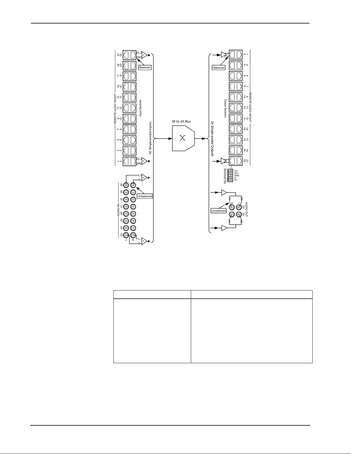
• 16 RCA inputs combine left and right channels to create eight
The C2N-IADS30X24 Intercom Audio Distribution Switcher (IADS) facilitates the
distribution and control of audio intercom signals for up to 22 touchpanels and door
stations using inexpensive CAT5E cable. The IADS integrates neatly with Crestron's
CNX-PAD8A and CNX-BIPAD8 audio distribution processors, enabling voice
paging from any microphone-equipped touchpanel to room loudspeakers throughout
the house or office, and allowing audio from central AV sources to be distributed to
any touchpanel.
The IADS is built around a fully programmable 30x24 audio crosspoint matrix,
providing extensive flexibility for the distribution of intercom and other monaural
audio signals. Interfaced through 22 bidirectional CAT5 audio ports, the matrix
provides complete freedom to route the microphone signal from any one touchpanel
or door station to the speakers in another, with real-time control to permit fluid
talk/listen (half-duplex) intercom functionality. Crestron offers several touchpanel
models equipped with built-in microphones and speakers designed for use with the
IADS. Door stations are easily implemented using the C2N-IIF Intercom Interface
(sold separately).
mono inputs.
• 22 CAT5 line inputs/outputs for door stations and TPS
touchpanels (remote audio in/out).
• 4 RCA outputs representing two mono channels by combining the
left and right channels of each audio input.
• 1 five-pin miniconnector for CNXTA telephone card interface for
dial-up paging and control.
• 1 four-pin miniconnector for Cresnet hookup.
• Built-in 30x24 audio crosspoint switch. Any mono input can be
routed to any mono output. Any output can be turned off,
providing a high-isolation off state.
• Touch-settable ID (TSID) ready.
Operations Guide – DOC. 6170A Intercom Audio Distribution System: C2N-IADS30X24 • 1
Page 6

Intercom Audio Distribution System Crestron C2N-IADS30X24
Eight unbalanced inputs are also provided to accept signals from the unbalanced
room outputs or loop-thru connectors of a Crestron audio distribution processor, or
from any stereo sources. Stereo input signals are internally summed to mono. Any
input signal may be freely routed to any number of CAT5 outputs. In addition, there
are two unbalanced outputs provided for connection to room inputs on the audio
distribution processor, allowing microphone and other signals to be routed to any set
of room speakers, easily accommodating the most complex zone-paging scheme.
Additional configurations can be achieved by interfacing CAT5 audio ports on the
IADS directly to CAT5 audio ports on the CNX-BIPAD8 and many other Crestron
products.
A 5-pin connector, paralleled with the last CAT5 I/O port, permits interfacing to
Crestron's CEN-TIA Telephone Interface Module (sold separately), enabling dial-up
paging through the client's phone system, and distribution of door chimes and other
sounds through the room loudspeakers.
The IADS functions as a slave device to any 2-Series control system communicating
via the Cresnet
®
control network.
Applications
Although the IADS can function alone as an intercom audio distribution controller, it
is ideally suited to work in combination with the C2N-IVDS24X24 (IVDS) intercom
video distribution system along with other Crestron audio/visual components and
TPS touchpanels to provide a variety of A/V functions throughout the facility. (Refer
to the simplified system diagram on page 3 and the functional diagram on page 4 for
more details.)
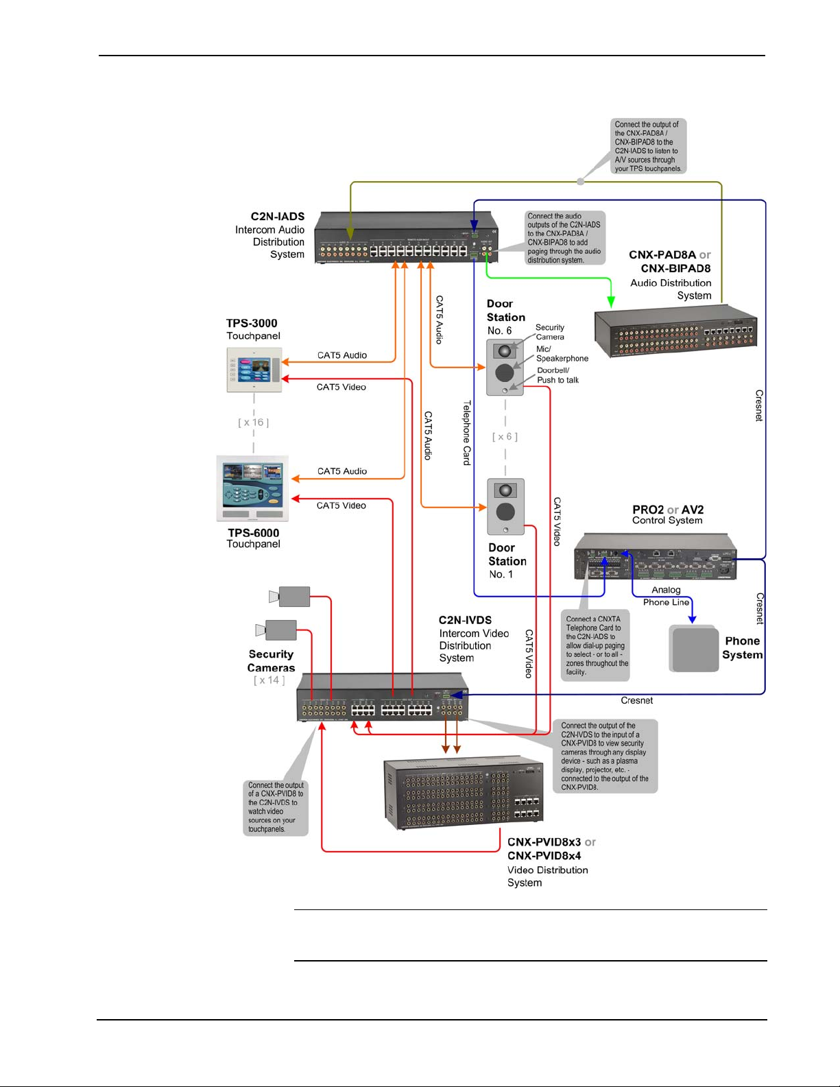
Paging
Connect the audio outputs of the IADS to a Crestron CNX-PAD8A (PAD8A) or
CNX-BIPAD8 (BIPAD8) audio distribution system to add whole facility paging
through the audio distribution system.
Connect a Crestron CNXTA telephone card (requires a control system that accepts
expansion cards) to the IADS to allow dial-up paging to specific or to all zones
throughout the facility.
A/V Source Monitoring
Connect the output of a PAD8A or BIPAD8 to the IADS to listen to A/V sources
through your TPS touchpanels.
Security Camera Monitoring
Connect the IVDS output to the input of a CNX-PVID8X4 or CNX-PVID8X3
(PVID8) video distribution system to view security camera output through any
display device, such as a plasma display or a projector, connected to the PVID8
output.
Video Monitoring
Connect the PVID8 output to the IVDS to watch video sources on your touchpanels.
Access Monitoring
Connect door station security camera, mic/speakerphone, and doorbell inputs and/or
outputs to the IADS and IVDS to monitor and control access to the facility from any
of your TPS touchpanels.
2 • Intercom Audio Distribution System: C2N-IADS30X24 Operations Guide - DOC. 6170A
Page 7
Crestron C2N-IADS30X24 Intercom Audio Distribution System
Simplified System Diagram
NOTE: The device types and quantities shown in the above diagram are for
illustrative purposes only. Your actual configuration is limited only by the number of
ports available, and could also contain multiple IADS and IVDS devices.
Operations Guide – DOC. 6170A Intercom Audio Distribution System: C2N-IADS30X24 • 3
Page 8
Intercom Audio Distribution System Crestron C2N-IADS30X24
C2N-IADS30X24 Functional Diagram
Specifications
Specifications for the IADS are listed in the following table.
C2N-IADS30X24 Specifications
SPECIFICATION DETAILS
Balanced line performance
Audio input (RJ-45 connectors)
Audio output (RJ-45 connectors)
Isolation and bandwidth
(Continued on following page)
Differential line input impedance: 2k-Ohm
Maximum differential input level: 4V
Differential line output impedance: 100 Ohm nominal
Maximum differential output level: 4V
Gain: 0 dB
Maximum crosstalk: ≤ -80 dB @ 1 KHz
Minimum isolation: ≥ 80 dB @1 KHz
Bandwidth: (-3 dB) 10 KHz nominal
CMRR: >75 dB @ 20 Hz to 20 KHz
rms
nominal
rms
4 • Intercom Audio Distribution System: C2N-IADS30X24 Operations Guide - DOC. 6170A
Page 9

Crestron C2N-IADS30X24 Intercom Audio Distribution System
C2N-IADS30X24 Specifications (Continued)
SPECIFICATION DETAILS
Unbalanced line performance
Audio input (RCA connectors)
Audio output (RCA connectors)
Isolation and bandwidth
Default Net ID 46
Power Requirements 24 Watts (1.0 Amp max. @ 24 VDC)
C2N-IADS30X24 Firmware C2N-IADS30X24.v1.10.upg
Control System Update Files
2-Series Control System
MP2/MP2E
CNMSX-AV/Pro
CNRACKX/-DP
Environmental temperature 41° to 104°F (5° to 40°C)
Humidity 10% to 90% RH (non-condensing)
Rack space required 2U high, 1U wide
Dimensions Height: 3.47 in (8.81 cm) without feet
Weight 3.4 lb (1.5 kg)
1. The latest software versions can be obtained from the Crestron website. Refer to the NOTE following
these footnotes.
2. Crestron 2-Series control systems include the AV2 and PRO2. Consult the latest Crestron Product Catalog
for a complete list of 2-Series control systems.
3. CNX update files are required for either CNMSX-AV/Pro or CNXRACKX/-DP. Filenames for CNX
update files have a UPZ extension. To avoid program problems, make cer tain you are using the update file
with the correct suffix letter (e.g., W or X).
1, 2, 3
Input impedance: 10 k-Ohm nominal
Maximum input level: 2V
Line output impedance: 100 Ohm nominal
Maximum output level: 2V
Gain: 0dB
Maximum crosstalk: ≤ -80 dB @ 1 KHz
Minimum isolation: ≥ 80 dB @1 KHz
Bandwidth: (-3 dB) 10 KHz nominal
Version 3.061.CUZ or later
Version MP2-V3062.CUZ or later
Version 5.12.63X.UPZ or later
Version 5.12.63W.UPZ or later
Width: 17.10 in (43.43 cm) without ears
Depth: 8.68 in (22.05 cm)
rms
rms
NOTE: Crestron software and any files on the website are for Authorized Crestron
dealers and Crestron Authorized Independent Programmers (CAIP) only. New users
may be required to register to obtain access to certain areas of the site (including the
FTP site).
Physical Description
This section provides information on the connections, controls, and indicators
available on your C2N-IADS30X24.
C2N-IADS30X24 Physical View (Front)
Operations Guide – DOC. 6170A Intercom Audio Distribution System: C2N-IADS30X24 • 5
Page 10

Intercom Audio Distribution System Crestron C2N-IADS30X24
C2N-IADS30X24 Physical View (Rear)
C2N-IADS30X24 Overall Dimensions
Connectors, Controls, & Indicators
# CONNECTORS
,
DESCRIPTION
1
CONTROLS, &
INDICATORS
1
2
(Continued on following page)
6 • Intercom Audio Distribution System: C2N-IADS30X24 Operations Guide - DOC. 6170A
PWR LED
NET LED
This LED illuminates when 24 volts DC is
supplied to the IADS.
This LED illuminates when communication
between the control system and the IADS is
established (the unit is polled on the
network), indicating that the loaded SIMPL
Windows program has a network device
defined at the same Net ID as the IADS. The
LED flashes when communication occurs.
Page 11

Crestron C2N-IADS30X24 Intercom Audio Distribution System
23
TELEPHONE
Connectors, Controls, & Indicators (continued)
# CONNECTORS
CONTROLS, &
INDICATORS
1
,
DESCRIPTION
3 AUDIO IN (23 - 30)
These eight pairs of RCA jacks combine the
left and right channel stereo input to provide
L
single mono inputs to the cross-point switch.
R
4
REMOTE AUDIO
IN/OUT (1 – 22)
Pin 1
TAB
POSITION
DOWN
JACKS, REAR VIEW
(TYPICAL)
SETUP Pushbutton and
5
LED
2, 3, 4
The twenty-two, shielded RJ-45 connectors
provide for balanced line audio to/from
1
2
Pin 1
TAB
POSITION
UP
remote locations in the facility; one CAT5
stereo input and output per connector.
Pin 1 Audio In L +
Pin 2 Audio In L Pin 3 Audio In R +
Pin 4 Audio Out L +
Pin 5 Audio Out L Pin 6 Audio In R Pin 7 Audio Out R +
Pin 8 Audio Out R -
The SETUP pushbutton and its associated
LED are used for setup of the unit’s network
ID during the initial configuration of a Cresnet
system or when the device is being added or
replaced.
6
NET
24
ZY G
Four-position terminal block connector for
data and power. Connects to Cresnet control
network.
Pin 1 (24) Power Pin 2 (Y) Data
Pin 3 (Z) Data Pin 4 (G) Ground
7 (Chassis Ground)
Use this chassis screw to connect the audio
source(s) common ground(s) to the IADS.
8
5
This five-pin connector is used to connect the
IADS to a CNXTA telephone card mounted in
a control system. The connections are in
OUT+
GRND
IN+
IN-
OUT-
parallel with the REMOTE AUDIO IN/OUT
port 22.
9 AUDIO OUT
2423
The two pairs of RCA jacks provide
unbalanced audio from the crosspoint switch,
intended to be connected to a PAD8A or
L
BIPAD8 for distribution to multiple locations
in the facility.
R
1. Interface connectors for NET and TELEPHONE ports are provided with the unit.
2. All stereo inputs are converted to mono inside the unit; all outputs are mono (left = right).
3. When connecting the IADS to a BIPAD8 via CAT5, make sure that the IADS audio out
connected to the BIPAD8 audio in
audio out
4. For additional information on audio/video connections over CAT5, refer to the latest version of the
5. If the TELEPHONE connector is used, the REMOTE AUDIO IN/OUT port 22 must not be used.
pins.
Crestron CAT5 Wiring Reference Guide (Doc. 6137) which is available from the Crestron website
(www.crestron.com/manuals).
pins, and the IADS audio in pins are connected to the BIPAD8
pins are
Operations Guide – DOC. 6170A Intercom Audio Distribution System: C2N-IADS30X24 • 7
Page 12

Intercom Audio Distribution System Crestron C2N-IADS30X24
Industry Compliance
As of the date of manufacture, the IADS has been tested and found to comply with
specifications for CE marking and standards per EMC and Radiocommunications
Compliance Labelling.
NOTE: This device complies with part 15 of the FCC rules. Operation is subject to
the following two conditions: (1) these devices may not cause harmful interference,
and (2) these devices must accept any interference received, including interference
that may cause undesired operation.
This equipment has been tested and found to comply with the limits for a Class B
digital device, pursuant to part 15 of the FCC Rules. These limits are designed to
provide reasonable protection against harmful interference in a residential
installation. This equipment generates, uses and can radiate radio frequency energy
and, if not installed and used in accordance with the instructions, may cause harmful
interference to radio communications. However, there is no guarantee that
interference will not occur in a particular installation. If this equipment does cause
harmful interference to radio or television reception, which can be determined by
turning the equipment off and on, the user is encouraged to try to correct the
interference by one or more of the following measures:
Reorient or relocate the receiving antenna.
Increase the separation between the equipment and receiver.
Connect the equipment into an outlet on a circuit different from that to
which the receiver is connected.
Consult the dealer or an experienced radio/TV technician for help.
8 • Intercom Audio Distribution System: C2N-IADS30X24 Operations Guide - DOC. 6170A
Page 13

Crestron C2N-IADS30X24 Intercom Audio Distribution System
Setup
Network Wiring
When wiring the network, consider the following:
• Use Crestron Certified Wire.
• Use Crestron power supplies for Crestron equipment.
• Provide sufficient power to the system.
CAUTION: Insufficient power can lead to unpredictabl e resul t s or dam a ge
to the equipment. Please use the Crestron Power Calculator to help calculate
how much power is needed for the system
(http://www.crestron.com/calculators
• For larger networks, Use a Cresnet Hub/Repeater (CNXHUB) to maintain
signal quality.
).
For more details, refer to “
Check Network Wiring” on page 16.
CAT5 Wiring
In addition to Ethernet applications, Category 5 (CAT5) wiring is used by Crestron
for a variety of audio and video applications.
Crestron recommends using CresCAT-IM (or D) wire or other high-quality CAT5
cable for transmitting CAT5 audio signals.
When using a Crestron wiring solution, the CresCAT-IM (or D) wire can carry audio
and video signals up to 500 feet (observe distance limitations based upon power
consumption for the touchpanel (or other device) in use). For more information, refer
to the latest version of the Crestron CAT5 Wiring Reference Guide (Doc. 6137),
which is available for download from the Crestron website.
Identity Code
The Net ID of the IADS has been factory set to 46. The Net IDs of multiple IADS
devices in the same system must be unique. Net IDs are changed from a personal
computer (PC) via the Crestron Toolbox
When setting the Net ID, consider the following:
• The Net ID of each unit must match an ID code specified in the SIMPL
Windows program.
™
.
• Each network device must have a unique Net ID.
For more details, refer to the Crestron Toolbox help file.
Hardware Hookup
Rack Mounting
Operations Guide – DOC. 6170A Intercom Audio Distribution System: C2N-IADS30X24 • 9
The IADS can be mounted in a rack or stacked with other equipment. Two “ears” are
provided with the IADS so that the unit can be rack mounted. These ears must be
installed prior to mounting. Complete the following procedure to attach the ears to
the unit. The only tool required is a #2 Phillips screwdriver.
Page 14
Intercom Audio Distribution System Crestron C2N-IADS30X24
WARNING: To prevent bodily injury when mounting or servicing this unit in a
rack, take special precautions to ensure that the system remains stable. The following
guidelines are provided to ensure your safety:
• When mounting this unit in a partially filled rack, load the rack from the
bottom to the top with the heaviest component at the bottom of the rack.
• If the rack is provided with stabilizing devices, install the stabilizers before
mounting or servicing the unit in the rack.
NOTE: If rack mounting is not required, rubber feet are provided for tabletop
mounting or stacking. Apply the feet near the corner edges on the underside of the
unit. Refer to “Stacking” below for details.
NOTE: Reliable earthing of rack-mounted equipment should be maintained.
Particular attention should be given to supply connections other than direct
connections to the branch circuit. (e.g., use of power strips).
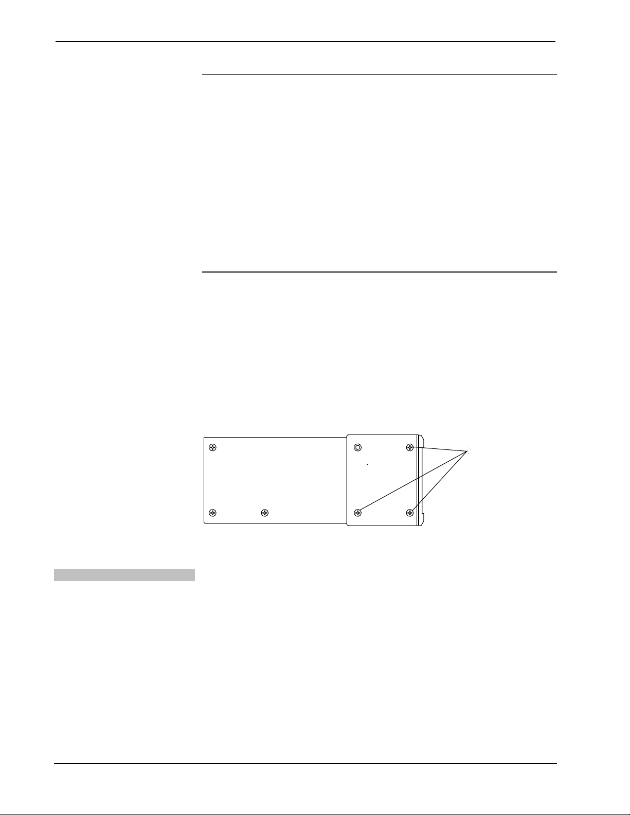
To install the ears:
1. There are screws that secure each side of the IADS top cover. Using a #2
Phillips screwdriver, remove the three screws closest to the front panel from
one side of the unit. Refer to the diagram following step 3 for a detailed
view.
Stacking
2. Position a rack ear so that its mounting holes align with the holes vacated
by the screws in step 1.
3. Secure the ear to the unit with three screws from step 1, as shown in the
following diagram.
Ear Attachment for Rack Mounting (Side View of Unit)
FASTEN WITH THREE
TOP COVER SCREWS
4. Repeat procedure (steps 1 through 3) to attach the remaining ear to the
opposite side.
Four "feet" are provided with the IADS so that if the unit is not rack mounted, the
rubber feet can provide stability when the unit is placed on a flat surface or stacked.
These feet should be attached prior to the hookup procedure. Refer to the following
illustration for placement of the feet.
10 • Intercom Audio Distribution System: C2N-IADS30X24 Operations Guide - DOC. 6170A
Page 15

Crestron C2N-IADS30X24 Intercom Audio Distribution System
Feet Location (Bottom View of Unit)
ATTACH FEET
NEAR CORNERS
OF THE UNIT
Connect the Device
Make the necessary connections as called out in the illustration that follows this
paragraph. Refer to “
Network Wiring” on page 9 before attaching the 4-position
terminal block connector. Apply power after all connections have been made.
When making connections to the IADS, use Crestron power supplies for Crestron
equipment.
Hardware Connections for the C2NIADS30X24
Operations Guide – DOC. 6170A Intercom Audio Distribution System: C2N-IADS30X24 • 11
Page 16

Intercom Audio Distribution System Crestron C2N-IADS30X24
Programming Software
Have a question or comment about Crestron software?
Answers to frequently asked questions (FAQs) can be viewed in the Online Help
section of the Crestron website. To post a question or view quest ions you have
submitted to Crestron’s True Blue Support, log in at
First-time users will need to establish a user account.
Earliest Version Software Requirements for the PC
NOTE: Crestron recommends that you use the latest software to take advantage of
the most recently released features. The latest software is available from the Crestron
website.
Crestron has developed an assortment of Windows®-based software tools to develop
a Cresnet system. The following are the minimum recommended software versions
for the PC:
http://support.crestron.com.
Software
TASK REQUIRED SOFTWARE VERSION
Program control system to
operate IADS.
Upload program and firmware. Crestron Toolbox 1.01.06 or later.
Program with simple wizards for
systems using an IADS
(optional but recommended).
SIMPL Windows version 2.04.14 or later
with SIMPL+ Cross Compiler version 1.1. or
later; Also requires Crestron Database
version 18.1.8 or later.
Crestron SystemBuilder™ version 1.0 or
later. Refer to software release notes or
Crestron website for other required
Crestron software packages.
Programming with Crestron SystemBuilder
Crestron SystemBuilder is the easiest method of programming, but does not offer as
much flexibility as SIMPL Windows. For additional details, download
SystemBuilder from the Crestron website and examine the extensive help file.
Programming with SIMPL Windows
NOTE: While SIMPL Windows can be used to program the IADS, it is
recommended to use SystemBuilder for configuring the system.
SIMPL Windows is Crestron’s premier software for programming Crestron control
systems. It is organized into two separate, but equally important “Managers”.
Configuration Manager
12 • Intercom Audio Distribution System: C2N-IADS30X24 Operations Guide - DOC. 6170A
Configuration Manager is the view where programmers “build” a Crestron control
system by selecting hardware from the Device Library.
• To incorporate the IADS into the system, drag the C2N-IADS30X24 from
the Cresnet Control Modules | Cresnet Audio Modules folder of the Device
Library and drop it in the System Views.
Page 17

Crestron C2N-IADS30X24 Intercom Audio Distribution System
Locating the IADS in the Device Library
• The system tree of the control system displays the device in the appropriate
slot with a default Net ID as shown in the following illustration.
C2Net Device, Slot 9
• Additional IADS devices are assigned different Net ID numbers as they are
added.
• If necessary, double click a device to open the “Device Settings” window
and change the Net ID, as shown in the following figure.
“C2N-IADS30X24 Device Settings” Window
• The ID code specified in the SIMPL Windows program must match the Net
ID of each unit.
Operations Guide – DOC. 6170A Intercom Audio Distribution System: C2N-IADS30X24 • 13
Page 18

Intercom Audio Distribution System Crestron C2N-IADS30X24
Programming Manager
Programming Manager is the view where programmers "program" a Crestron control
system by assigning signals to symbols. The symbol can be viewed by double
clicking on the icon or dragging it into Detail View. A descr i pti on f or each si gnal i n
the symbol is described in the SIMPL Windows help file (F1).
Example Program
An example program for the IADS is available from the Crestron website
http://www.crestron.com/exampleprograms).
(
14 • Intercom Audio Distribution System: C2N-IADS30X24 Operations Guide - DOC. 6170A
Page 19

Crestron C2N-IADS30X24 Intercom Audio Distribution System
Uploading and Upgrading
Crestron recommends using the latest programming software and that each device
contains the latest firmware to take advantage of the most recently released features.
However, before attempting to upload or upgrade, it is necessary to establish
communication.
Establishing Communication
Use Crestron Toolbox for communicating with the IADS; refer to the Crestron
Toolbox help file for details. There is a single method of communication: indirect
serial communication.
Indirect Serial Communication
• IADS connects to control system via Cresnet.
• Establish communications between the PC and the control system as
described in the latest version of the 2-Series Reference Guide (Doc. 6256).
Programs and Firmware
• Display the network device tree (Tools | Network Device Tree) to show all
network devices connected to the control system. Right-click on the IADS
to display actions that can be performed on the IADS:
⇒ Upgrade firmware
⇒ Change Net ID
• Upload the SIMPL Windows file to the control system using SIMPL
Windows or Crestron Toolbox.
• Upgrade IADS firmware via Crestron Toolbox.
⇒ Establish serial communications with the IADS and display the
“System Info” window.
⇒ Select Functions | Firmware… to upgrade the IADS firmware .
For details on uploading and upgrading, refer to the SIMPL Windows help file or the
Crestron Toolbox help file.
Operations Guide – DOC. 6170A Intercom Audio Distribution System: C2N-IADS30X24 • 15
Page 20

Intercom Audio Distribution System Crestron C2N-IADS30X24
Problem Solving
Troubleshooting
The following table provides corrective action for possible trouble situations. If
further assistance is required, please contact a Crestron customer service
representative.
C2N-IADS30X24 Troubleshooting
TROUBLE
Power LED does
not Illuminate
NET LED does
not illuminate
Hum on audio. Grounding problem. Either connect or remove chassis ground wire.
POSSIBLE
CAUSE(S)
IADS is not
receiving power.
Loose network
connection.
Improper Net ID. Verify that IADS Net ID matches Net ID in
Verify that cable plugged into networkport is
secure. Ensure sufficient network power to
support all NET devices.
Verify that cable plugged into NET port is
secure.
software program. Refer to "Identity Code."
CORRECTIVE ACTION
Use the Right Wire
Calculate Power
Check Network Wiring
In order to ensure optimum performance over the full range of your installation
topology, Crestron Certified Wire, and only Crestron Certified Wire, may be used.
Failure to do so may incur additional charges if support is required to identify
performance deficiencies because of using improper wire.
CAUTION: Use only Crestron power supplies for Crestron equipment. Failure to do so
could cause equipment damage or void the Crestron warranty.
CAUTION: Provide sufficient power to the system. Insufficient power can lead to
unpredictable results or damage to the equipment. Please use the Crestron Power
Calculator to help calculate how much power is needed for the system
(http://www.crestron.com/calculators
When calculating the length of wire for a particular Cresnet run, the wire gauge and the
Cresnet power usage of each network unit to be connected must be taken into
consideration. Use Crestron Certified Wire only. If Cresnet units are to be daisy-chained
on the run, the Cresnet power usage of each network unit to be daisy-chained must be
added together to determine the Cresnet power usage of the entire chain. If the unit is a
home-run from a Crestron system power supply network port, the Cresnet power usage
of that unit is the Cresnet power usage of the entire run. The wire gauge and the Cresnet
power usage of the run should be used in the following equation to calculate the cable
length value on the equation’s left side.
Cable Length Equation
L = Length of run (or chain) in feet
R = 6 Ohms (Crestron Certified Wire: 18 AWG (0.75 MM ))
P = Cresnet power usage of entire run (or chain)
L <
40,000
Where:
R x P
Make sure the cable length value is less than the value calculated on the right side of the
equation. For example, a Cresnet run using 18 AWG Crestron Certified Wire and
drawing 20 watts should not have a length of run more than 333 feet. If Cresnet HP is
used for the same run, its length could extend to 1250 feet.
).
or 1.6 Ohms (Cr esn et HP: 12 AWG (4 MM ))
2
2
16 • Intercom Audio Distribution System: C2N-IADS30X24 Operations Guide - DOC. 6170A
Page 21

Crestron C2N-IADS30X24 Intercom Audio Distribution System
NOTE: All Crestron certified Cresnet wiring must consist of two twisted pairs. One
twisted pair is the +24V conductor and the GND conductor, and the other twisted pair is
the Y conductor and the Z conductor.
Strip and Tin Wire
Add Hubs
When daisy-chaining Cresnet units, strip the ends of the wires carefully to avoid
nicking the conductors. Twist together the ends of the wires that share a pin on the
network connector, and tin the twisted connection. Apply solder only to the ends of the
twisted wires. Avoid tinning too far up the wires or the end becomes brittle. Insert the
tinned connection into the Cresnet connector and tighten the retaining screw. Repeat
the procedure for the other three conductors.
For larger networks (i.e., greater than 28 network devices), it may become necessary to
add a Cresnet Hub/Repeater (CNXHUB) to maintain signal quality throughout the
network. Also, for networks with lengthy cable runs, it may be necessary to add a
Hub/Repeater after only 20 devices.
Reference Documents
The latest version of all documents mentioned within the guide can be obtained from
the Crestron website (
of product manuals arranged in alphabetical order by model number.
List of Related Reference Documents
2-Series Control Systems Reference Guide
CAT5 Wiring Reference Guide
http://www.crestron.com/manuals). This link will provide a list
DOCUMENT TITLE
Further Inquiries
If you cannot locate specific information or have questions after reviewing this
guide, please take advantage of Crestron's award winning customer service team by
calling the Crestron corporate headquarters at 1-888-CRESTRON [1-888-273-7876].
For assistance in your local time zone, refer to the Crestron website
http://www.crestron.com/) for a listing of Crestron worldwide offices.
(
You can also log onto the online help section of the Crestron website to ask
questions about Crestron products. First-time users will need to establish a user
account to fully benefit from all available features.
Future Updates
As Crestron improves functions, adds new features, and extends the capabilities of
the IADS, additional information may be made available as manual updates. These
updates are solely electronic and serve as intermediary supplements prior to the
release of a complete technical documentation revision.
Check the Crestron website periodically for manual update availability and its
relevance. Updates are identified as an “Addendum” in the Download column.
Operations Guide – DOC. 6170A Intercom Audio Distribution System: C2N-IADS30X24 • 17
Page 22

Intercom Audio Distribution System Crestron C2N-IADS30X24
Return and Warranty Policies
Merchandise Returns / Repair Service
1. No merchandise may be returned for credit, exchange, or service without prior authorization
from CRESTRON. To obtain warranty service for CRESTRON products, contact an
authorized CRESTRON dealer. Only authorized CRESTRON dealers may contact the factory
and request an RMA (Return Merchandise Authorization) number. Enclose a note specifying
the nature of the problem, name and phone number of contact person, RMA number, and
return address.
2. Products may be returned for credit, exchange, or service with a CRESTRON Return
Merchandise Authorization (RMA) number. Authorized returns must be shipped freight
prepaid to CRESTRON, 6 Volvo Drive, Rockleigh, N.J. or its authorized subsidiaries, with
RMA number clearly marked on the outside of all cartons. Shipments arriving freight collect
or without an RMA number shall be subject to refusal. CRESTRON reserves the right in its
sole and absolute discretion to charge a 15% restocking fee, plus shipping costs, on any
products returned with an RMA.
3. Return freight charges following repair of items under warranty shall be paid by CRESTRON,
shipping by standard ground carrier. In the event repairs are found to be non-warranty, return
freight costs shall be paid by the purchaser.
CRESTRON Limited Warranty
CRESTRON ELECTRONICS, Inc. warrants its products to be free from manufacturing defects in material s
and workmanship under normal use for a period of three (3) years from the date of purchase from
CRESTRON, with the following exceptions: disk drives and any other moving or rotating mechanical
parts, pan/tilt heads and power supplies are covered for a period of one (1) year; touchscreen display and
overlay components are covered for 90 days; batteries and incandescent lamps are not covered.
This warranty extends to products purchased directly from CRESTRON or an authorized CRESTRON
dealer. Purchasers should inquire of the dealer regarding the natur e and extent of the dealer's warranty, if
any.
CRESTRON shall not be liable to honor the terms of this warranty if the product has been used in any
application other than that for which it was intended, or if it has been subjected to misuse, accidental
damage, modification, or improper installation procedures. Furthermore, this warranty does not cover any
product that has had the serial number altered, defaced, or rem oved.
This warranty shall be the sole and exclusive remedy to the original purchaser. In no event shall
CRESTRON be liable for incidental or consequential damages of any kind (property or economic damages
inclusive) arising from the sale or use of this equipment. CRESTRON is not liable for any claim made by a
third party or made by the purchaser for a third party.
CRESTRON shall, at its option, repair or replace any product found defective, without charge for parts or
labor. Repaired or replaced equipment and parts supplied under this warranty shall be covered only by the
unexpired portion of the warranty.
Except as expressly set forth in this warranty, CRESTRON makes no other warranties, expressed or
implied, nor authorizes any other party to offer any warranty, includ ing any implied warranties of
merchantability or fitness for a particular purpose. Any implied warranties that may be imposed by law are
limited to the terms of this limited warranty. This warranty statement supersedes all previous warranties.
Trademark Information
All brand names, product names, and trademarks are the sole property of their respective owner s. Windows is a registered trademark
of Microsoft Corporation. Windows95/98/Me/XP and WindowsNT/2000 are tradem arks of Microsoft Corporation.
18 • Intercom Audio Distribution System: C2N-IADS30X24 Operations Guide - DOC. 6170A
Page 23

Crestron C2N-IADS30X24 Intercom Audio Distribution System
This page is intentionally left blank.
Operations Guide – DOC. 6170A Intercom Audio Distribution System: C2N-IADS30X24 • 19
Page 24

Crestron Electronics, Inc. Operations Guide – DOC. 6170A
15 Volvo Drive Rockleigh, NJ 07647 (2008775)
Tel: 888.CRESTRON 09.06
Fax: 201.767.7576 Specifications subject to
www.crestron.com change without notice.
 Loading...