

Page 1

Crestron C2N-DEMO
Lighting Case
Reference Guide
Page 2

This document was prepared and written by the Technical Documentation department at:
Crestron Electronics, Inc.
15 Volvo Drive
Rockleigh, NJ 07647
1-888-CRESTRON
All brand names, product names, and trademarks are the property of their respective owners.
©2004 Crestron Electronics, Inc.
Page 3

Crestron C2N-DEMO Lighting Case Demonstration Case
Contents
Crestron Demonstration Case: C2N-DEMO Lighting Case
Introduction ...............................................................................................................................1
Features and Functions................................................................................................ 1
Case Contents.............................................................................................................. 2
Setup............................................................................................................................ 2
System Functionality ................................................................................................................. 4
Button Models ............................................................................................................. 4
Feedback Types........................................................................................................... 5
Interfaces ..................................................................................................................... 6
Appendix: Factory Settings ....................................................................................................17
Return and Warranty Policies.................................................................................................. 19
Merchandise Returns / Repair Service ...................................................................... 19
CRESTRON Limited Warranty ................................................................................19
1
Reference Guide – DOC. 6282 Contents • i
Page 4

Page 5

Crestron C2N-DEMO Lighting Case Demonstration Case
Crestron Demonstration Case:
C2N-DEMO Lighting Case
Introduction
Features and Functions
The Crestron® C2N-DEMO Lighting Case (herein known as the Lighting Case) is a
pre-programmed Crestron system in a portable case. It is designed with the sales
person in mind to give customers a basic understanding of Crestron automation and
lighting systems. The Lighting Case is programmed entirely in Crestron D3 Pro
programming software to allow for a more realistic demonstration of Crestron
hardware and software packages. In order for this demo to function properly, it must
be used in conjunction with the Crestron C2N-DEMO Interface Case.
The Crestron C2N-DEMO Lighting Case (Opened)
Reference Guide – DOC. 6282 Crestron Demonstration Case: C2N-DEMO Lighting Case • 1
Page 6

Demonstration Case Crestron C2N-DEMO Lighting Case
Case Contents
The following table summarizes the products contained within the Lighting Case.
Contents of the Lighting Case
MODEL DESCRIPTION QTY
PAC2 2-Series Control Processor 1
C2ENET-2 Dual Port WAN/LAN Ethernet Card 1
CLX-1DIM8 1 – 20 AMP Feed, 8 – Controlled Circuits 1
CLT-1DIM8 Termination Block for the CLX-1DIM8 1
CAEN-2x1 Automation Cabinet with 2 Module Slots 1
The Lighting Case also ships with two cables:
• Power Cable
• Cross-over Cable
There are eight light bulbs representing loads at one end of the case. The loads are
identified in the following illustration.
Loads in the Lighting Case
MASTER
BATH
DOWNLIGHTS
MASTER
BEDROOM
FAMILY
ROOM
REAR
HALL
LIGHTS
KITCHEN
DOWNLIGHTS
DINING
CHANDELIER
BEDROOM
DOWNLIGHTS
Setup
Complete the following steps to setup your portable Lighting Case.
1. Apply Power
Open the case lid, simply plug the supplied power cord into the side of
the case (exterior face, near the large handle), and then into a standard
120 VAC wall receptacle.
NOTE: The following step describes the IP setup for a Windows
system. The procedure may vary slightly for other systems.
2. Set IP Address
To setup the static IP address for your laptop, go to Start | Settings |
Control Panel and double click Network Connections.
Right click on the icon for your Ethernet adapter and select Properties.
Highlight the Internet Protocol (TCP/IP) selection and click the
Properties button.
Select the radio button labeled Use the following IP address: and enter
in the following information.
GUEST
GUEST
BATHROOM
DOWNLIGHTS
XP operating
2 • Crestron Demonstration Case: C2N-DEMO Lighting Case Reference Guide – DOC. 6282
Page 7

Crestron C2N-DEMO Lighting Case Demonstration Case
“Internet Protocol (TCP/IP) Properties” Window
Click on OK to exit and save settings.
NOTE: The PAC2 utilizes a dual port Ethernet card with firewall enabled. Use this
as a point for discussions regarding system security. Refer to step 4 for accessing a
web page through a firewall.
3. Ethernet Cable
Connect the supplied Ethernet cross-over cable between the Lighting
Case Ethernet port (marked LAN A) and the Ethernet port on your
laptop. Use the Ethernet cross-over cable supplied with the Crestron
C2N-DEMO Interface Case to connect the Ethernet port on the
Interface Case with the Lighting Case Ethernet port (marked LAN B).
NOTE: Unless you have a hub, a standard Ethernet cable does not work when
connecting the Lighting Case to your laptop.
4. Web Page
Open Internet Explorer on your laptop and type in the following
address: http://192.168.1.2:8080
specially defined path through the firewall. Use this opportunity to
discuss other security features such as SSL (Secure Socket Layer).
. The “:8080” portion allows for a
Reference Guide – DOC. 6282 Crestron Demonstration Case: C2N-DEMO Lighting Case • 3
Page 8

Demonstration Case Crestron C2N-DEMO Lighting Case
System Functionality
This section describes each interface and how it is intended to function. This
information should be useful in how you approach your sales presentation, enabling
you to concentrate on the features most relevant to your customer.
Since this system was programmed in D3 Pro, it is important to understand what
features are available as they apply to each interface. The first thing to examine is
the way buttons can be programmed. This is defined as a “Button Model” in D3 Pro.
There is a wide variety of button models available to suit particular applications. All
of these models are listed with a description of how each function.
Button Models
Single Press
The single press button model provides one programmable event, meaning that when
you press this button, it always does the same thing.
Single Press + Dim
The single press + dim button model adds dimming capabilities to the single press
button model. If you press and release the button within 0.5 seconds, the button
operates normally. If you hold the button for longer than 0.5 seconds, the button
enters multi-dim mode. Once in this dimming mode, each alternate press of the
button ‘dims up’ or ‘dims down’ all the lights assigned to this button. That is, each
time the dim operation is activated, the lights dim in the opposite direction from the
last dimming operation. If all the lights are currently off, then the lights always ‘dim
up’.
NOTE: Multi-dim mode is a function of a press and hold. When a hold is released,
normal single press functionality resumes.
Toggle
The toggle button model has two programmable events generally referred to as the
on and off events. Each one of the events can be programmed independently, but are
usually programmed so that the first tap of the button turns on a light or lights to a
preset level and the second press turns it or them off.
Toggle + Dim
The toggle + dim button model adds dimming capabilities to the toggle button
model. If you press and release the button within 0.5 seconds, the button operates
normally. If you hold the button for longer than 0.5 seconds, the button enters multidim mode. Once in this dimming mode, each alternate press of the button ‘dims up’
or ‘dims down’ all the lights assigned to the press 1 event. That is, each time the dim
operation is activated, the lights dim in the opposite direction from the last dimming
operation. If all the lights are currently off, then the lights always ‘dim up’.
NOTE: Multi-dim mode is a function of a press and hold. When a hold is released,
normal toggle functionality resumes.
4 • Crestron Demonstration Case: C2N-DEMO Lighting Case Reference Guide – DOC. 6282
Page 9

Crestron C2N-DEMO Lighting Case Demonstration Case
Multi-Press
The multi-press button model triggers different actions each time the button is
pressed, to a maximum of 10 button presses. If the button is not pressed after a
specified period, a timeout event occurs and the button resets. Thus, the next button
press triggers the first event. A timeout is also an event that can trigger actions. If the
timeout period is set to 0 seconds, then the timeout event never occurs and the button
simply cycles through each press action. By default, this button model generates
momentary feedback for each press, and blinks once when the timeout event occurs.
Tap and Hold
The tap and hold button model triggers different actions depending on whether the
user taps the button, or presses and holds the button for a specified ‘hold time’. By
default, this button model generates momentary feedback for a tap and blinking
feedback for a hold.
Timeout
The timeout button model triggers one or more actions when the user presses the
button, as with a single press button model. If the button is not pressed again for a
specified time (as set in the timeout field) then a timeout event occurs, which also
triggers actions. Pressing the button when the timer is still counting re-triggers the
press event and restarts the timer. By default, this button model generates
momentary feedback while the button is pressed, and blinks when the timeout
occurs.
Press and Release
The press/release button model triggers one set of actions when the button is pressed
and a different set of actions when it is released. In this way, you can assign actions
to both the rising and falling edge of the button press signal. By default, this button
model generates momentary feedback.
Master Raise/Lower
A master raise or lower button model raises or lowers all the lights associated with
the last button that was pressed on the keypad.
Learnable Lighting
Learnable lighting is a button model modifier. The toggle and single press have this
option that allows the end user to dynamically change and resave the lighting levels
programmed to the press event. To use this feature, simply manually adjust light
levels for a given scene. Then press and hold the scene button that has learnable
lighting selected.
Feedback Types
In addition to button models, each model also has selectable feedback types. Some
feedback types are applicable to all button models while others are more specific.
Always On
The button’s feedback is always active (e.g., LED is always illuminated).
Reference Guide – DOC. 6282 Crestron Demonstration Case: C2N-DEMO Lighting Case • 5
Page 10

Demonstration Case Crestron C2N-DEMO Lighting Case
Always Off
The button’s feedback is always inactive (e.g., LED is never illuminated).
Momentary
The button’s feedback is active while the button is being pressed and inactive when
the button is released.
On when ANY light in preset is ON
The button’s feedback is active if any of the lights assigned to the button’s press or
tap event are above 0%.
On when ALL lights in preset are ON
The button’s feedback is active only if all the lights assigned to the button’s press or
tap event are above 0%.
On when ALL lights are at PRESET LEVEL
The button’s feedback is active only if all the lights assigned to the button’s press or
tap event are at their target values.
Linked to a device output
This type of feedback links the button’s feedback directly to another device in the
program. When you select a device from the Source Device list, the Output Signal
list provides the digital outputs per the device. Once you select the device and output
signal, the button’s feedback is active for as long as that output signal is high.
Interfaces
This section reviews each interface in the system and describes the features and
functions of each button press. If the button provides lighting control, these
descriptions utilize the aforementioned information such as button model and
feedback type. In addition to this, each button description lists the lighting load it
controls in the virtual house.
NOTE: The light bulbs in the demonstration case only refer to one zone of lights in
one room of the virtual house. The entire house can be monitored from the web
project under the monitor selection.
NOTE: The eight light bulbs represent loads. Refer to “Case Contents” on page 2
for an illustration.
NOTE: The following abbreviations are used, if applicable. Button model is
abbreviated as BM. Feedback type is abbreviated as FB.
6 • Crestron Demonstration Case: C2N-DEMO Lighting Case Reference Guide – DOC. 6282
Page 11

Crestron C2N-DEMO Lighting Case Demonstration Case
CNX-B2 (Dining Room)
1.536
1.5360"
This interface was programmed as a secondary interface for the dining room in this
system. The entire virtual house can be monitored from the web page project
associated with this system.
2.9119"
2.912
DINNER
PARTY
MUSIC
1.067
1.0670"
4.762
4.7619"
Button 1 (DINNER PARTY)
[BM = Single Press / Learnable, FB = On when ALL lights are at PRESET
LEVEL, Loads = Dining Chandelier, Dining Downlights, Dining Sconces]
When this button is pressed, it turns on all loads to a preset level over a defined
period.
Button 2 (MUSIC)
When this button is pressed the first time, it turns on the virtual audio system. Each
additional press of the button scrolls through the sources. In order to better
demonstrate this function, audio files have been stored to announce what source is
currently active. The audio level is adjusted from the other dining room keypad (the
CNX-B8).
CNX-B4 (Master Bedroom)
1.5360"
1.536
2.9119"
2.912
LIGHTS
LIGHTING
OVERRIDE
TEMP
TEMP
1.0670"
1.067
4.762
4.7619"
Reference Guide – DOC. 6282 Crestron Demonstration Case: C2N-DEMO Lighting Case • 7
Page 12

Demonstration Case Crestron C2N-DEMO Lighting Case
This interface was programmed as a secondary interface for the master bedroom.
The entire virtual house can be monitored from the web page project associated with
this system.
Button 1 (LIGHTS)
[BM = Toggle + Dim, FB = Toggle, Loads = Master Bed Downlights, Master
Bed Downlights2]
On press 1, this button turns on all loads to a preset level and then off again on press
2.
Button 2 (LIGHTING OVERRIDE)
[BM = Tap and Hold, FB = Connected to Relay, Loads = Relay 1 on PAC2]
When this button is pressed, the relay opens. When the button is held, the relay
closes.
Button 3 (K TEMP)
This button changes the CHV-THSTAT’s set point up by one degree with each
press. Have your customer watch the front panel display of the thermostat or one of
the graphical user interfaces as they display the same data.
Button 4 (TEMP J)
This button functions the same as K TEMP, but increments the set point down.
CNX-B6 (Bathroom)
1.536
1.5360"
This interface was programmed as the primary control point for the guest bathroom.
The entire virtual house can be monitored from the web page project associated with
this system.
MORNING
VANITY
FAN
2.912
2.9119"
EVENING
DOWN
LIGHTS
ALL
OFF
1.067
1.0670"
4.762
4.7619"
8 • Crestron Demonstration Case: C2N-DEMO Lighting Case Reference Guide – DOC. 6282
Page 13

Crestron C2N-DEMO Lighting Case Demonstration Case
Button 1 (MORNING)
[BM = Single Press / Learnable, FB = On when ALL lights are at PRESET
LEVEL, Loads = Bath Vanity, Bath Downlights]
When this button is pressed, it turns on all loads to a preset level over a defined
period.
Button 2 (EVENING)
[BM = Single Press / Learnable, FB = On when ALL lights are at PRESET
LEVEL, Loads = Bath Vanity, Bath Downlights]
When this button is pressed, it turns on all loads to a preset level over a defined
period.
Button 3 (VANITY)
[BM = Toggle + Dim, FB = Toggle, Loads = Bath Vanity]
On press 1, this button turns the load to a preset level and then off again on press 2.
Button 4 (DOWN LIGHTS)
[BM = Toggle + Dim, FB = Toggle, Loads = Bath Downlights]
On press 1, this button turns the load to a preset level and then off again on press 2.
Button 5 (FAN)
[BM = Timeout, FB = Blink until Timeout, Loads = Bath Exhaust Fan]
When this button is pressed, the load turns on until the timeout occurs at which point
the load shuts off. If the button is pressed before the timeout occurs, the timer resets.
Button 6 (ALL OFF)
[BM = Single Press, FB = Momentary, Loads = Bath Vanity, Bath Downlights]
When this button is pressed, it turns all loads off over a defined period.
CNX-B8 (Dining Room)
1.536
1.5360"
DINNER
PARTY
SCONCE
MUSIC
SOURCE
2.9119"
2.912
CHAND
DOWN
LIGHTS
VOL
VOL
1.067
1.0670"
4.762
4.7619"
Reference Guide – DOC. 6282 Crestron Demonstration Case: C2N-DEMO Lighting Case • 9
Page 14

Demonstration Case Crestron C2N-DEMO Lighting Case
This interface was programmed as the primary control point for the dining room.
The entire virtual house can be monitored from the web page project associated with
this system.
Button 1 (DINNER PARTY)
[BM = Single Press / Learnable, FB = On when ALL lights are at PRESET
LEVEL, Loads = Dining Chandelier, Dining Downlights, Dining Sconce]
When this button is pressed, it turns on all loads to a preset level over a defined
period.
Button 2 (CHAND)
[BM = Toggle + Dim, FB = Toggle, Loads = Chandelier]
On press 1, this button turns the load to a preset level and then off again on press 2.
Button 3 (SCONCE)
[BM = Toggle + Dim, FB = Toggle, Loads = Dining Sconce]
On press 1, this button turns the load to a preset level and then off again on press 2.
Button 4 (DOWN LIGHTS)
[BM = Toggle + Dim, FB = Toggle, Loads = Dining Downlights]
On press 1, this button turns the load to a preset level and then off again on press 2.
Button 5 (MUSIC)
This button toggles the audio system for the dining room on and off. The feedback
LED illuminates when the audio system is active.
Button 6 (K VOL)
This button increases the volume level of the virtual audio system. The feedback
LED illuminates only while the button is pressed.
Button 7 (SOURCE)
This button cycles through the various virtual audio sources. The feedback LED
illuminates only while the button is pressed. Audio WAV files are triggered with the
selection of each new source. This demonstrates how even a simple interface such a
keypad can give detailed feedback information.
Button 8 (VOL J)
This button decreases the volume level of the virtual audio system. The feedback
LED illuminates only while the button is pressed.
10 • Crestron Demonstration Case: C2N-DEMO Lighting Case Reference Guide – DOC. 6282
Page 15

Crestron C2N-DEMO Lighting Case Demonstration Case
CNX-B12 (Master Bathroom)
1.5360"
1.536
2.912
2.9119"
MORN
NOON VANITY
EVEN
CLOSETS
RELAX
MUSIC
SOURCE
DOWN
FAN
VOL +
VOL -
4.762
4.7619"
1.067
1.0670"
This interface was programmed as the primary control point for the master
bathroom. The entire virtual house can be monitored from the web page project
associated with this system.
NOTE: The CNX-B12 is designated for the master bathroom and the CNX-B2 is
designated for the dining room. Both are ganged together in the case to conserve
space and to demonstrate how two keypads can be mounted together.
Button 1 (MORN)
[BM = Single Press / Learnable, FB = On when ALL lights are at PRESET
LEVEL, Loads = Bath Vanity, Bath Ceiling Lights, Bath Downlights]
When this button is pressed, it turns on all loads to a preset level over a defined
period.
Button 2 (DOWN)
[BM = Toggle + Dim, FB = Toggle, Loads = Bath Downlights]
On press 1, this button turns the load to a preset level and then off again on press 2.
Button 3 (NOON)
[BM = Single Press / Learnable, FB = On when ALL lights are at PRESET
LEVEL, Loads = Bath Vanity, Bath Ceiling Lights, Bath Downlights]
When this button is pressed, it turns on all loads to a preset level over a defined
period.
Button 4 (VANITY)
[BM = Toggle + Dim, FB = Toggle, Loads = Bath Vanity]
On press 1, this button turns the load to a preset level and then off again on press 2.
Reference Guide – DOC. 6282 Crestron Demonstration Case: C2N-DEMO Lighting Case • 11
Page 16

Demonstration Case Crestron C2N-DEMO Lighting Case
Button 5 (EVEN)
[BM = Single Press / Learnable, FB = On when ALL lights are at PRESET
LEVEL, Loads = Bath Vanity, Bath Ceiling Lights, Bath Downlights]
When this button is pressed, it turns on all loads to a preset level over a defined
period.
Button 6 (CLOSETS)
[BM = Toggle + Dim, FB = Toggle, Loads = Bath Ceiling Lights]
On press 1, this button turns the load to a preset level and then off again on press 2.
Button 7 (RELAX)
[BM = Single Press / Learnable, FB = On when ALL lights are at PRESET
LEVEL, Loads = Bath Vanity, Bath Ceiling Lights, Bath Downlights]
When this button is pressed, it turns on all loads to a preset level over a defined
period.
Button 8 (FAN)
[BM = Timeout, FB = Blink until Timeout, Loads = Bath Exhaust Fan]
When this button is pressed, the load turns on until the timeout occurs at which point
the load shuts off. If the button is pressed before the timeout occurs, the timer resets.
Button 9 (MUSIC)
This button toggles the audio system for the master bathroom on and off. The
feedback LED illuminates when the audio system is active.
Button 10 (VOL +)
This button increases the volume level of the virtual audio system. The feedback
LED illuminates only while the button is pressed.
Button 11 (SOURCE)
This button cycles through the various virtual audio sources. The feedback LED
illuminates only while the button is pressed. Audio WAV files are triggered with the
selection of each new source. This demonstrates how even a simple interface such a
keypad can give detailed feedback information.
Button 12 (VOL -)
This button decreases the volume level of the virtual audio system. The feedback
LED illuminates only while the button is pressed.
12 • Crestron Demonstration Case: C2N-DEMO Lighting Case Reference Guide – DOC. 6282
Page 17

Crestron C2N-DEMO Lighting Case Demonstration Case
C2N-DB6 (Family Room)
4.158
1.788
FRONT LAMP
REAR
FAMILY
PARTY
1.067
FAN
1.696
2.696
1.532
This interface was programmed as the primary control point for the family room.
The entire virtual house can be monitored from the web page project associated with
this system.
Button 1 (FRONT)
[BM = Toggle + Dim, FB = Toggle, Loads = Front Downlights]
On press 1, this button turns the load to a preset level and then off again on press 2.
Button 2 (LAMP)
[BM = Toggle + Dim, FB = Toggle, Loads = Lamp]
On press 1, this button turns the load to a preset level and then off again on press 2.
Button 3 (REAR)
[BM = Toggle + Dim, FB = Toggle, Loads = Rear Downlights]
On press 1, this button turns the load to a preset level and then off again on press 2.
Button 4 (FAN)
[BM = Multi-press, FB = Connected to Fan, Loads = Ceiling Fan]
This button turns on the fan and selects various speeds. The first press sets the fan to
speed 4, the second press to speed 3, then to speed 2, speed 1, and finally back to the
off state.
Button 5 (FAMILY)
[BM = Toggle / Learnable, FB = On when ALL lights are at PRESET LEVEL,
Loads = Front Downlights, Rear Downlights, Lamp]
On press 1, this button turns the loads to a preset level and then off again on press 2.
Button 6 (PARTY)
[BM = Single Press, FB = On when ALL lights are at PRESET LEVEL, Loads
= Family Front Downlights, Family Rear Downlights, Family Lamp, Entry
Reference Guide – DOC. 6282 Crestron Demonstration Case: C2N-DEMO Lighting Case • 13
Page 18

Demonstration Case Crestron C2N-DEMO Lighting Case
Chandelier, Bath Vanity, Bath Downlights, Breakfast Chandelier, Dining Room
Lights, Hall 1 Lights, Hall 2 Lights, Front Porch]
When this button is pressed, it turns all loads to a preset level over a defined period.
If it is past sunset, the front porch light illuminates as well.
C2N-DB8 (Entry)
4.158
1.788
HOME AWAY
PATH
PORCH
MUSIC
VOL +
VOL -SRC
1.067
1.696
2.696
1.532
This interface was programmed as the primary control point for the entry. The entire
virtual house can be monitored from the web page project associated with this
system.
Button 1 (HOME)
[BM = Single Press, FB = On when ALL lights are at PRESET LEVEL, Loads
= Family Front Downlights, Family Rear Downlights, Family Lamp, Entry
Chandelier, Kitchen Downlights, Kitchen Pendants, Breakfast Chandelier,
Master Bed Lights, Master Bath Lights, Hall 1 Lights, Hall 2 Lights]
When this button is pressed, it turns all loads to a preset level over a defined period.
Button 2 (AWAY)
[BM = Single Press, FB = On when ALL lights are at PRESET LEVEL, Loads
= ALL LOADS]
When this button is pressed, it turns all loads off over a defined period.
Button 3 (PATH)
[BM = Toggle / Learnable, FB = Toggle, Loads = Hall 1 Lights, Hall 2 Lights,
Kitchen Downlights, Kitchen Pendants, Entry Chandelier]
On press 1, this button turns the loads to a preset level and then off again on press 2.
Button 4 (PORCH)
[BM = Toggle + Dim, FB = Toggle, Loads = Porch Downlights]
On press 1, this button turns the load to a preset level and then off again on press 2.
14 • Crestron Demonstration Case: C2N-DEMO Lighting Case Reference Guide – DOC. 6282
Page 19

Crestron C2N-DEMO Lighting Case Demonstration Case
Button 5 (MUSIC)
This button toggles the audio system in the common areas of the virtual home on and
off. The feedback LED illuminates when the audio system is active.
Button 6 (VOL +)
This button increases the volume level of the virtual audio system. The feedback
LED illuminates only while the button is pressed.
Button 7 (SRC)
This button cycles through the various virtual audio sources. The feedback LED
illuminates only while the button is pressed. Audio WAV files are triggered with the
selection of each new source. This demonstrates how even a simple interface such a
keypad can give detailed feedback information.
Button 8 (VOL -)
This button decreases the volume level of the virtual audio system. The feedback
LED illuminates only while the button is pressed.
C2N-DB12 (Entry)
1.532
4.158
1.788
DOWN FAN
LAMP RAISE
PATH LOWER
VOL +
XM
MP3
VOL -
1.067
OFFCD
1.696
2.696
This interface was programmed as the primary control point for the entry. The entire
virtual house can be monitored from the web page project associated with this
system.
Button 1 (DOWN)
[BM = Toggle + Dim, FB = Toggle, Loads = Downlights]
On press 1, this button turns the load to a preset level and then off again on press 2.
Button 2 (FAN)
This button turns on the fan and selects various speeds. The first press sets the fan to
speed 4, the second press to speed 3, then to speed 2, speed 1, and finally back to the
off state. The feedback LED illuminates whenever the fan is on.
Reference Guide – DOC. 6282 Crestron Demonstration Case: C2N-DEMO Lighting Case • 15
Page 20

Demonstration Case Crestron C2N-DEMO Lighting Case
Button 3 (LAMP)
[BM = Toggle + Dim, FB = Toggle, Loads = Lamp]
On press 1, this button turns the load to a preset level and then off again on press 2.
Button 4 (RAISE)
[BM = Master Raise, FB = Momentary, Loads = Last Selected]
Button 5 (PATH)
[BM = Toggle / Learnable, FB = On when ALL lights are at PRESET LEVEL,
Loads = Bedroom Lamp, Bath Vanity, Bath Downlights, Hall 2 Downlights]
On press 1, this button turns the loads to a preset level and then off again on press 2.
Button 6 (LOWER)
[BM = Master Lower, FB = Momentary, Loads = Last Selected]
Button 7 (XM)
This button turns on the virtual audio system and selects the XM radio for the
source.
Button 8 (VOL +)
This button raises the volume level of the virtual audio system.
Button 9 (MP3)
This button turns on the virtual audio system and selects the MP3 server for the
source.
Button 10 (VOL -)
This button lowers the volume level of the virtual audio system.
Button 11 (CD)
This button turns on the virtual audio system and selects the CD player for the
source.
Button 12 (OFF)
This button turns off the virtual audio system and deselects the current source.
Discuss the possibility of this same button resetting the default volume level in the
room, stopping all the transport decks, and shutting off the amplifier.
Touchpanel Interfaces
Due to the vast number of possibilities associated with touchpanel interfaces, it is not
realistic to provide a detailed button-by-button overview of functionality. We trust
the interfaces were designed in an intuitive self-explaining manner. Please call Bill
Schafer for further explanation of system functionality.
16 • Crestron Demonstration Case: C2N-DEMO Lighting Case Reference Guide – DOC. 6282
Page 21

Crestron C2N-DEMO Lighting Case Demonstration Case
Appendix: Factory Settings
The C2N-DEMO Lighting Case ships completely configured. In the event that the
original factory settings are altered, corrupted, or erased, the following information
is necessary for reconfiguring the processor in each case.
C2N-DEMO Interface Case:
• IP address is 192.168.40.11
• Subnet mask is 255.255.255.0
• Default router is 192.168.40.10
C2N-DEMO Lighting Case:
LAN A
• IP address is 192.168.1.2
• Subnet mask is 255.255.255.0
• Default router is 192.168.1.1
LAN B
• IP address is 192.168.40.10
• Subnet mask is 255.255.255.0
• Default router is 0.0.0.0
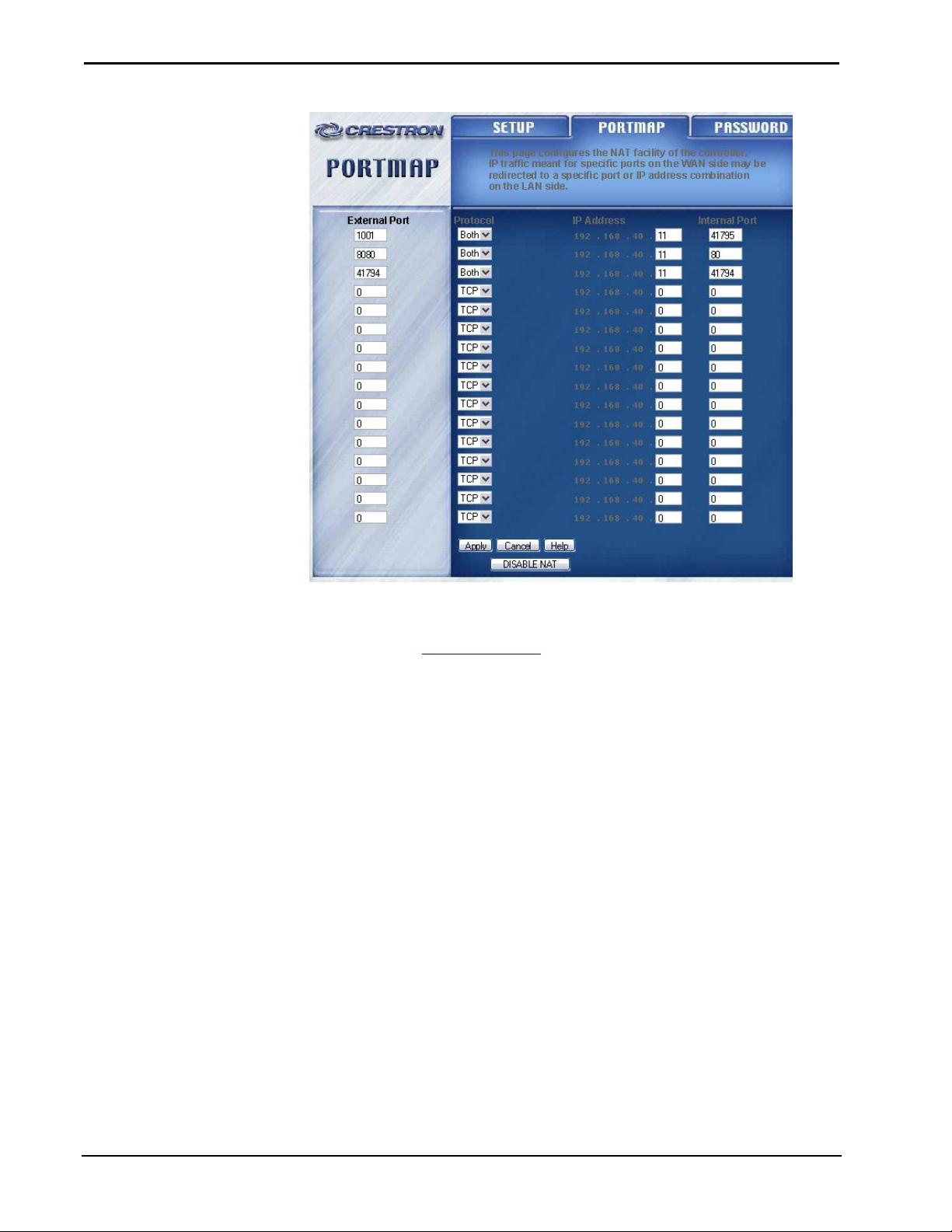
The Network Address Translator (NAT) setting for the Ethernet card in the
processor is as follows:
Reference Guide – DOC. 6282 Crestron Demonstration Case: C2N-DEMO Lighting Case • 17
Page 22
Demonstration Case Crestron C2N-DEMO Lighting Case
Details on NAT can be found in the latest version of the NAT Reference Guide
(Doc. 6001), which can be found on the Downloads | Product Manuals page of the
Crestron website (www.crestron.com
).
18 • Crestron Demonstration Case: C2N-DEMO Lighting Case Reference Guide – DOC. 6282
Page 23

Crestron C2N-DEMO Lighting Case Demonstration Case
Return and Warranty Policies
Merchandise Returns / Repair Service
1. No merchandise may be returned for credit, exchange, or service without prior
authorization from CRESTRON. To obtain warranty service for CRESTRON products,
contact the factory and request an RMA (Return Merchandise Authorization) number.
Enclose a note specifying the nature of the problem, name and phone number of contact
person, RMA number, and return address.
2. Products may be returned for credit, exchange, or service with a CRESTRON Return
Merchandise Authorization (RMA) number. Authorized returns must be shipped freight
prepaid to CRESTRON, 6 Volvo Drive, Rockleigh, N.J., or its authorized subsidiaries,
with RMA number clearly marked on the outside of all cartons. Shipments arriving
freight collect or without an RMA number shall be subject to refusal. CRESTRON
reserves the right in its sole and absolute discretion to charge a 15% restocking fee, plus
shipping costs, on any products returned with an RMA.
3. Return freight charges following repair of items under warranty shall be paid by
CRESTRON, shipping by standard ground carrier. In the event repairs are found to be
non-warranty, return freight costs shall be paid by the purchaser.
CRESTRON Limited Warranty
CRESTRON ELECTRONICS, Inc. warrants its products to be free from manufacturing defects in
materials and workmanship under normal use for a period of three (3) years from the date of
purchase from CRESTRON, with the following exceptions: disk drives and any other moving or
rotating mechanical parts, pan/tilt heads and power supplies are covered for a period of one (1)
year; touchscreen display and overlay components are covered for 90 days; batteries and
incandescent lamps are not covered.
This warranty extends to products purchased directly from CRESTRON or an authorized
CRESTRON dealer. Purchasers should inquire of the dealer regarding the nature and extent of the
dealer's warranty, if any.
CRESTRON shall not be liable to honor the terms of this warranty if the product has been used in
any application other than that for which it was intended, or if it has been subjected to misuse,
accidental damage, modification, or improper installation procedures. Furthermore, this warranty
does not cover any product that has had the serial number altered, defaced, or removed.
This warranty shall be the sole and exclusive remedy to the original purchaser. In no event shall
CRESTRON be liable for incidental or consequential damages of any kind (property or economic
damages inclusive) arising from the sale or use of this equipment. CRESTRON is not liable for any
claim made by a third party or made by the purchaser for a third party.
CRESTRON shall, at its option, repair or replace any product found defective, without charge for
parts or labor. Repaired or replaced equipment and parts supplied under this warranty shall be
covered only by the unexpired portion of the warranty.
Except as expressly set forth in this warranty, CRESTRON makes no other warranties, expressed
or implied, nor authorizes any other party to offer any warranty, including any implied warranties
of merchantability or fitness for a particular purpose. Any implied warranties that may be imposed
by law are limited to the terms of this limited warranty. This warranty statement supercedes all
previous warranties.
Trademark Information
All brand names, product names, and trademarks are the sole property of their respective owners. Windows is a registered
trademark of Microsoft Corporation. Windows95/98/Me/XP and WindowsNT/2000 are trademarks of Microsoft
Corporation.
Reference Guide – DOC. 6282 Crestron Demonstration Case: C2N-DEMO Lighting Case • 19
Page 24

Crestron Electronics, Inc. Reference Guide – DOC. 6282
15 Volvo Drive Rockleigh, NJ 07647 09.04
Tel: 888.CRESTRON
Fax: 201.767.7576 Specifications subject to
www.crestron.com change without notice.
 Loading...