

Page 1

Crestron MSMK-4SM
Multi-Surface Mount Kit for the
TPMC-4SM Series
Installation Guide
Page 2
This document was prepared and written by the Technical Documentation department at:
Crestron Electronics, Inc.
15 Volvo Drive
Rockleigh, NJ 07647
1-888-CRESTRON
Regulatory Compliance
As of the date of manufacture, the MSMK-4SM has been tested and found to comply with specifications for CE
marking and standards per EMC and Radiocommunications Compliance Labelling.
All brand names, product names and trademarks are the property of their respective owners.
©2010 Crestron Electronics, Inc.
Page 3

Crestron MSMK-4SM Multi-Surface Mount Kit for the TPMC-4SM Series
Contents
Multi-Surface Mount Kit for the TPMC-4SM Series: MSMK-4SM 1
Introduction ...............................................................................................................................1
Setup .......................................................................................................................................... 2
Supplied Hardware...................................................................................................... 2
Installation................................................................................................................... 5
Resources................................................................................................................................. 16
Further Inquiries........................................................................................................ 16
Future Updates ..........................................................................................................16
Return and Warranty Policies.................................................................................................. 17
Merchandise Returns / Repair Service ......................................................................17
CRESTRON Limited Warranty.................................................................................17
Installation Guide – DOC. 6848B Contents • i
Page 4

Page 5
Crestron MSMK-4SM Multi-Surface Mount Kit for the TPMC-4SM Series
Multi-Surface Mount Kit for the
TPMC-4SM Series: MSMK-4SM
Introduction
The Crestron® MSMK-4SM provides a versatile surface mounting solution for the
TPMC-4SM Series Crestron Isys
MSMK-4SM, the touchpanel can be mounted directly to glass, granite, marble,
plaster, smooth stone and masonry, or virtually any other flat surface using either the
self-adhering mounting plate or screws. An optional angle bracket is included to
allow the touchpanel to be mounted at a fixed tilt of 20 degrees up or down.
An adhesive backed raceway is also provided for use on smooth surfaces to conceal
wires running to the touchpanel from the floor or ceiling. The raceway is paintable,
and is composed of three 3 foot (0.91 meter) sections plus an assortment of elbows
and couplings.
Models
DESCRIPTION MODEL NUMBER COLOR
the TPMC-4SM Series
For simplicity within this guide the color and texture designation are omitted and the
term “MSMK-4SM” is used, unless otherwise noted.
®
4.3" Wall Mount Touchpanels. Using the
MSMK-4SM-B-S Gloss Black Multi-Surface Mount Kit for
MSMK-4SM-W-S Gloss White
Installation Guide – DOC. 6848B Multi-Surface Mount Kit for the TPMC-4SM Series: MSMK-4SM • 1
Page 6

Multi-Surface Mount Kit for the TPMC-4SM Series Crestron MSMK-4SM
Setup
Supplied Hardware
The MSMK-4SM consists of a plastic surface mount enclosure, metal mounting
plate with adhesive backing, angled mounting bracket, plastic covers to protect
cabling openings, raceway and appropriate screws and nuts for mounting.
The multi-surface mounting option provides the necessary support and accessories
for post-construction applications. The table below lists all parts included with the
MSMK-4SM.
Supplied Hardware for the MSMK-4SM
DESCRIPTION PART NUMBER COLOR QUANTITY
Metal, Plate, Glass Mount,
Foam with Adhesive
Plastic Enclosure, Surface
Mount
Bracket, 20 Degree Mount
Raceway 2024932 White 1
Nut, #04-40, External, Hex 2004878 N/A 4
Screw, #04-40 x 1/4”, Steel,
Pan Head, Phillips
4509195
4509522
2024381
2024382
2024621
2024622
2024491
2024492
2007161 N/A 4
Gloss
White
Gloss
Black
Gloss
White
Gloss
Black
Gloss
White
Gloss
Black
Gloss
White
Gloss
Black
1
1
1
1
1
1
2 Plastic Cover
2
2 • Multi-Surface Mount Kit for the TPMC-4SM Series: MSMK-4SM Installation Guide – DOC. 6848B
Page 7
Crestron MSMK-4SM Multi-Surface Mount Kit for the TPMC-4SM Series
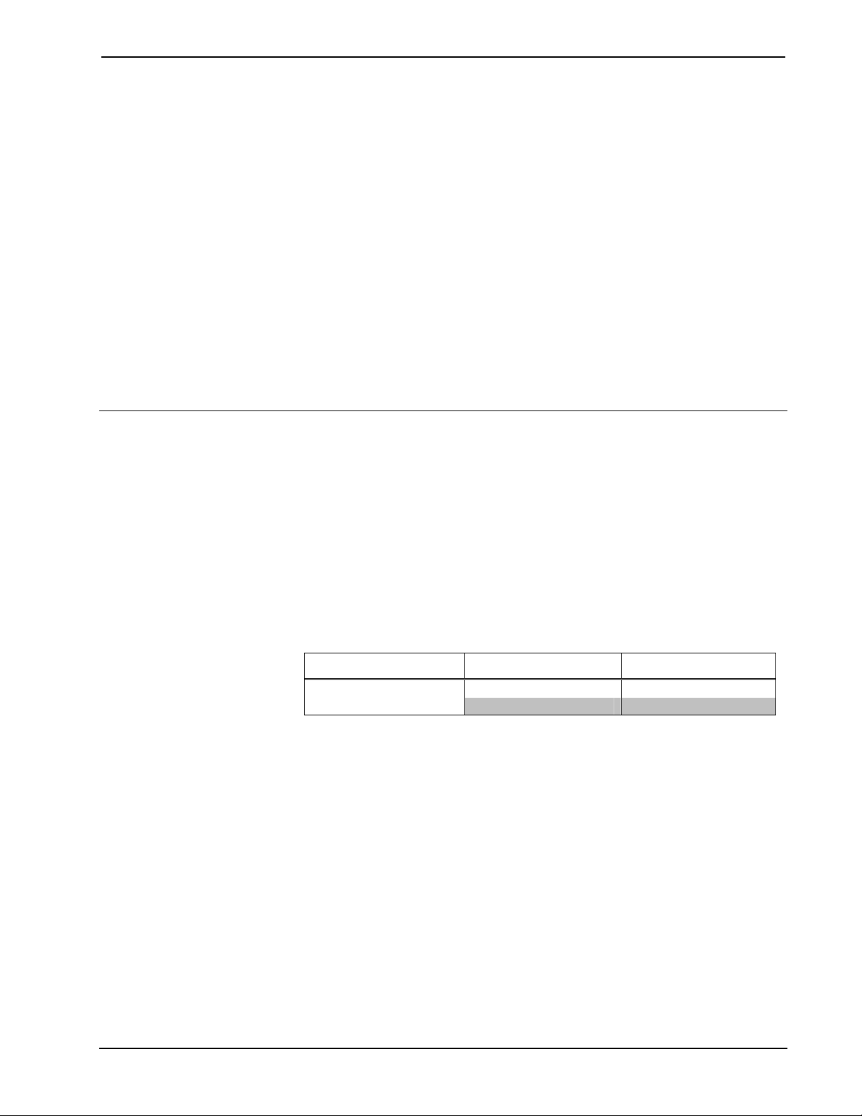
The dimensions of the MSMK-4SM are shown below and on the following page.
Glass Mounting Plate Overall Dimensions
4.50 in
(115 mm)
3.00 in
(77 mm)
Angle Mounting Bracket Overall Dimensions
2.72 in
(69 mm)
4.25 in
(108 mm)
0.23 in
(6 mm)
1.12 in
(29 mm)
Installation Guide – DOC. 6848B Multi-Surface Mount Kit for the TPMC-4SM Series: MSMK-4SM • 3
Page 8
Multi-Surface Mount Kit for the TPMC-4SM Series Crestron MSMK-4SM
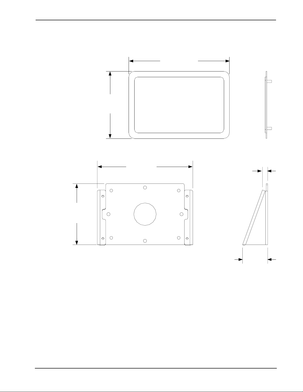
Plastic Enclosure Overall Dimensions (Rear View)
3.75 in
(96 mm)
3.00 in
(77 mm)
2.00 in
(51 mm)
2.10 in
(54 mm)
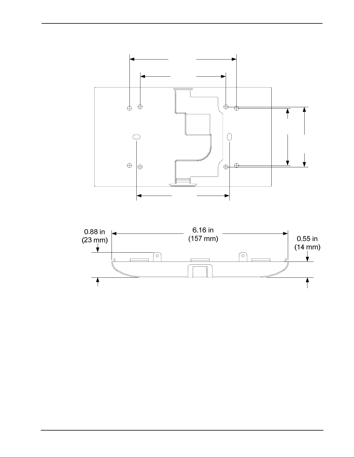
Plastic Enclosure Overall Dimensions (Bottom View)
3.25 in
(83 mm)
4 • Multi-Surface Mount Kit for the TPMC-4SM Series: MSMK-4SM Installation Guide – DOC. 6848B
Page 9

Crestron MSMK-4SM Multi-Surface Mount Kit for the TPMC-4SM Series
Installation
This section provides an installation procedure for each mounting scenario. The
“Glass Mounting Procedure” starts below, the “Drywall, Paneling, Concrete or Brick
Mounting Procedure” starts on page 11 and the “Raceway Mounting Procedure”
starts on page 15. Be sure to review each procedure before starting.
Glass Mounting Procedure
The touchpanel can be mounted to a flat pane of glass or similar smooth surfaces
(e.g., granite, marble, plaster, smooth stone and masonry) using the included glass
mounting plate. The back of the plate has an adhesive tape that permanently attaches
to the glass. The touchpanel can be flat mounted or angle mounted to the glass
mounting plate, follow the appropriate procedure below. After installation is
complete, the raceway kit may be installed on a smooth surface. Refer to “Raceway
Mounting Procedure” on page 15.
NOTE: Ensure the glass mounting surface is cleaned with a glass cleaning product
that does not leave a film and is free of debris before mounting. Once glass mounting
plate has been attached, it cannot be easily removed.
Flat Mount
Complete the following procedure to attach the glass mounting plate. The only tools
and supplies required and not supplied are a level, tape, #2 Phillips tip screwdriver,
1/4” hex driver and a glass cleaning product that does not leave a film. A T8 Torx bit
is supplied with the touchpanel.
1. Thoroughly clean and dry the glass mounting surface using a glass cleaning
product that does not leave a film.
2. Using the level, carefully tape a horizontal reference line that will coincide
with the lower edge of the mounting bracket.
CAUTION: Adhesive on glass mounting plate is a high strength bond.
Once adhesive meets a surface, it cannot be easily removed or adjusted.
3. Remove the adhesive backing from the glass mounting plate.
4. Holding the glass mounting plate (4509195 or 4509522) at a 45 degree
angle to the glass, carefully align the lower edge of the mounting plate with
the level taped line. Do not allow adhesive backing to come in contact with
the glass.
5. Once aligned with the level reference line, carefully tilt the glass mounting
plate back until it is secured to the glass. Firmly press glass mounting plate
to the glass to ensure proper adhesion and that any trapped air bubbles are
removed.
6. Using a flathead screwdriver, carefully separate the back cover of the
touchpanel from the front of the unit. This part will not be re-used. Refer to
the illustration on the following page for visual guidance.
Installation Guide – DOC. 6848B Multi-Surface Mount Kit for the TPMC-4SM Series: MSMK-4SM • 5
Page 10

Multi-Surface Mount Kit for the TPMC-4SM Series Crestron MSMK-4SM
Separate Back Cover of Touchpanel
Insert screwdriver to separate back of Touchpanel
NOTE: If installed, the two security screws must be removed
before separating the back cover of the touchpanel.
7. Insert plastic cover (2024491 or 2024492) into top or bottom of plastic
enclosure (2024381 or 2024382). Installation location of plastic cover is
determined through the location of the raceway. For example, if the
raceway is to be run to the top of the plastic enclosure, install the plastic
cover in the bottom of the plastic enclosure.
8. Run the RJ-45 network wiring through the hole in the back of the plastic
enclosure.
9. Attach the plastic enclosure to the glass mounting plate using the 1/4” hex
driver and the four included #04-40 hex nuts (2004878). Observe
orientation of the TOP screening to ensure proper installation of plastic
enclosure. Refer to the illustration below for visual guidance.
Plastic Enclosure Mounting Using Glass Mounting Plate
Glass
Glass Mounting Plate
(4509195 or 4509522)
Plastic Cover
(2024491 or 2024492)
Nut (4) #04-40 Hex
(2004878)
Plastic Enclosure
(2024381 or 2024382)
6 • Multi-Surface Mount Kit for the TPMC-4SM Series: MSMK-4SM Installation Guide – DOC. 6848B
Page 11

Crestron MSMK-4SM Multi-Surface Mount Kit for the TPMC-4SM Series
NOTE: When raceway is run to the bottom of the touchpanel, the plastic cover must
be placed in the top of the plastic enclosure. When raceway is run to the top of the
touchpanel, the plastic cover must be placed in the bottom of the plastic enclosure.
10. Connect the RJ-45 network wiring to the touchpanel and then install the
touchpanel by carefully pressing the unit into place. While snapping the unit
into place, pull the RJ-45 network wiring to remove slack. Refer to the
illustration on the below for visual guidance.
NOTE: Use care when pulling plenum rated cable through the bottom of the plastic
enclosure; the rigidity of the cable will cause slight resistance.
Touchpanel Mounting Using Glass Mounting Plate (Exploded View)
Glass
Glass Mounting Plate
(4509195 or 4509522)
Touchpanel
(Sold Separately)
Plastic Cover
(2024491 or 2024492)
Plastic Enclosure
(2024381 or 2024382)
Nut (4) #04-40 Hex
(2004878)
11. Secure touchpanel to the plastic enclosure with Phillips head screws.
Alternatively, security Torx screws can be installed using a Torx
screwdriver bit (both included with touchpanel), as shown in the illustration
on the following page.
Installation Guide – DOC. 6848B Multi-Surface Mount Kit for the TPMC-4SM Series: MSMK-4SM • 7
Page 12

Multi-Surface Mount Kit for the TPMC-4SM Series Crestron MSMK-4SM
Secure Touchpanel with Screws (Mounting Surface Not Shown)
Angle Mount
To install the angle mounting bracket, complete steps 1-7 of the previous “Flat
Mount” procedure. Continue with this procedure to assemble the angle mounting
bracket with the glass mounting plate.
1. Using a 1/4” hex driver, install the angle mounting bracket (2024621 or
2024622) to the glass mounting plate with the four included hex nuts
(2004878). Refer to the illustration on the following page for visual
guidance.
NOTE: Angle mounting bracket may be oriented to tilt the touchpanel
20 degrees up or down and depending on the application.
8 • Multi-Surface Mount Kit for the TPMC-4SM Series: MSMK-4SM Installation Guide – DOC. 6848B
Page 13

Crestron MSMK-4SM Multi-Surface Mount Kit for the TPMC-4SM Series
Attach Angle Mounting Bracket
Glass
Glass Mounting Plate
(4509195 or 4509522)
Angle Mounting Bracket
(2024621 or 2024622)
Nut (4) #04-40 Hex
(2004878)
2. Run the RJ-45 network wiring through the hole in the back of the
plastic enclosure.
3. Attach the plastic enclosure (2024381 or 2024382) to the angle
mounting bracket with the four included #04-40 x 1/4” Phillips head
screws (2007161), as shown in the illustration on the following page.
Observe orientation of the TOP screening to ensure proper installation
of plastic enclosure.
Installation Guide – DOC. 6848B Multi-Surface Mount Kit for the TPMC-4SM Series: MSMK-4SM • 9
Page 14

Multi-Surface Mount Kit for the TPMC-4SM Series Crestron MSMK-4SM
Attach Plastic Enclosure to Angle Mounting Bracket
Glass Mounting Plate
(4509195 or 4509522)
Angle Mounting Bracket
(2024621 or 2024622)
Glass
Screw (4) #04-40 x 1/4"
Pan Head, Phillips
(2007161)
NOTE: When raceway is run to the bottom of the touchpanel, the plastic cover must
be placed on the top of the plastic enclosure. When raceway is run to the top of the
touchpanel, the plastic cover must be placed on the bottom of the plastic enclosure.
Plastic Enclosure
(2024381 or 2024382)
4. Connect the RJ-45 network wiring to the touchpanel and then install the
touchpanel by carefully pressing the unit into place. While snapping the
unit into place, pull the RJ-45 network wiring to remove slack. Refer to
the illustration on the following page for visual guidance.
10 • Multi-Surface Mount Kit for the TPMC-4SM Series: MSMK-4SM Installation Guide – DOC. 6848B
Page 15

Crestron MSMK-4SM Multi-Surface Mount Kit for the TPMC-4SM Series
Touchpanel Mounting Using MSMK-4SM and Angle Mounting Bracket (Exploded View)
Screw (4) #04-40 x 1/4"
Pan Head, Phillips
(2007161)
Glass Mounting Bracket
Glass
(4509195 or 4509522)
Angle Mounting Bracket
(2024621 or 2024522)
Plastic Enclosure
(2024381 or 2024382)
Touchpanel
(Sold Separately)
Flat Mount
5. Secure touchpanel to the plastic enclosure with Phillips head screws.
Alternatively, security Torx screws can be installed using a Torx
screwdriver bit (both included with touchpanel), as shown in the
illustration on page 8.
Drywall, Paneling, Concrete or Brick Mounting Procedure
This section provides the necessary steps for the assembly and installation of the
MSMK-4SM onto drywall, paneling, concrete or brick. The touchpanel can be flat
mounted or angle mounted to the surface, follow the appropriate procedure below.
After installation is complete, the raceway may be installed following the procedure
on page 15.
Review the procedure and complete the steps in the order provided. The only tools
or materials required and not supplied are appropriate drywall or concrete screws,
#2 Phillips tip screwdriver, 1/4” hex driver and a level. A T8 Torx bit is supplied
with the touchpanel.
1. Insert plastic cover (2024491 or 2024492) into top or bottom of plastic
enclosure (2024381 or 2024382). Installation location of plastic cover
is determined by the location of the raceway. For example, if the
raceway is to be run to the top of the plastic enclosure, install plastic
cover to bottom in plastic enclosure.
2. Run the RJ-45 network wiring through the hole in the back of the
plastic enclosure.
Installation Guide – DOC. 6848B Multi-Surface Mount Kit for the TPMC-4SM Series: MSMK-4SM • 11
Page 16

Multi-Surface Mount Kit for the TPMC-4SM Series Crestron MSMK-4SM
3. Using the level and appropriate screws, mount the back plastic
enclosure (2024381 or 2024382). Observe orientation of the TOP
screening to ensure proper installation of the plastic enclosure.
4. Using a flathead screwdriver, carefully separate the back cover of the
touchpanel from the front of the unit. This part will not be re-used.
5. Connect the RJ-45 network wiring to the touchpanel and then install the
touchpanel by carefully pressing the unit into place. While snapping the
unit into place, pull the RJ-45 network wiring to remove slack. Refer to
the illustration below for visual guidance.
NOTE: Use care when pulling plenum rated cable through the bottom of the plastic
enclosure; the rigidity of the cable will cause slight resistance.
Mount Touchpanel to Drywall with Raceway
NOTE: Raceway can be run to the top or bottom of the touchpanel.
NOTE: When raceway is run to the bottom of the touchpanel, the plastic cover must
be inserted in the top of the plastic enclosure. When raceway is run to the top of the
touchpanel, the plastic cover must be inserted in the bottom of the plastic enclosure.
NOTE: Raceway is intended to be installed on smooth surfaces such as drywall or
glass.
12 • Multi-Surface Mount Kit for the TPMC-4SM Series: MSMK-4SM Installation Guide – DOC. 6848B
Page 17

Crestron MSMK-4SM Multi-Surface Mount Kit for the TPMC-4SM Series
6. Secure touchpanel to the plastic enclosure with Phillips head screws.
Alternatively, security Torx screws can be installed using a Torx
screwdriver bit (both included with touchpanel), as shown in the
illustration on page 8.
Angle Mount
Mount Angle Mounting Bracket to Mounting Surface
Mounting
Surface
Angle Mounting Bracket
(2024621 or 2024622)
Drywall or
Concrete
Screws (2)
1. Using the level and appropriate screws, mount the angle mounting
bracket (2024621 or 2024622). Refer to the illustration below for visual
guidance.
2. Insert plastic cover (2024491 or 2024492) into top or bottom of plastic
enclosure (2024381 or 2024382). Installation location of plastic cover
is determined by the location of the raceway. For example, if the
raceway is to be run to the top of the plastic enclosure, install plastic
cover in bottom of plastic enclosure.
3. Run the RJ-45 network wiring through the hole in the back of the
plastic enclosure.
Installation Guide – DOC. 6848B Multi-Surface Mount Kit for the TPMC-4SM Series: MSMK-4SM • 13
Page 18

Multi-Surface Mount Kit for the TPMC-4SM Series Crestron MSMK-4SM
4. Attach plastic enclosure to angle mounting bracket with the four
included #04-40 x 1/4” Phillips head screws (2007161). Observe
orientation of the TOP screening to ensure proper installation of plastic
enclosure. Refer to the illustration below for visual guidance.
Attach Plastic Enclosure to Angle Mounting Bracket
Mounting
Surface
Angle Mounting Bracket
(2024621 or 2024622)
Plastic Cover
(2024491 or 2024492)
Screw (4) #04-40 x 1/4"
Pan Head, Phillips
(2007161)
5. Using a flathead screwdriver, carefully separate the back plastic of the
touchpanel from the front of the unit. This part will not be re-used.
6. Connect the RJ-45 network wiring to the touchpanel and then install the
touchpanel by carefully pressing the unit into place. While snapping the
unit into place, pull the RJ-45 network wiring to remove slack. Refer to
the illustration on the following page for visual guidance.
14 • Multi-Surface Mount Kit for the TPMC-4SM Series: MSMK-4SM Installation Guide – DOC. 6848B
Plastic Enclosure
(2024381 or 2024382)
Page 19

Crestron MSMK-4SM Multi-Surface Mount Kit for the TPMC-4SM Series
Touchpanel Mounting Using MSMK-4SM and Angle Mounting Bracket (Exploded View)
Mounting
Surface
Angle Mounting Bracket
(2024621 or 2024622)
Plastic Cover
(2024491 or 2024492)
Touchpanel
(Sold Separately)
Screw (4) #04-40 x 1/4"
Pan Head, Phillips
(2007161)
7. Secure touchpanel to the plastic enclosure with Phillips head screws.
Alternatively, security Torx screws can be installed using a Torx
screwdriver bit (both included with touchpanel), as shown in the
illustration on page 8.
Plastic Enclosure
(2024381 or 2024382)
Raceway Mounting Procedure
This section provides the necessary steps for the assembly and installation of the
raceway to conceal and organize cabling to the touchpanel. The kit contains three
cable channels, two flat elbows, one inside elbow, one outside elbow, and two
couplings.
The raceway may be run to either the top or bottom of the touchpanel. Review the
procedure and complete the steps in the order provided. After installation, the
raceway can be painted.
NOTE: Surface must be clean before installation.
NOTE: Do not use on textured surfaces.
NOTE: The raceway is intended for installation on smooth surfaces, such as glass,
drywall or paneling.
1. Cut raceway to desired length.
2. Insert cables into raceway and press to snap shut.
3. Peel liner from the back of the raceway to expose adhesive strip.
4. Press firmly against wall. Use elbows and couplings as necessary.
Installation Guide – DOC. 6848B Multi-Surface Mount Kit for the TPMC-4SM Series: MSMK-4SM • 15
Page 20

Multi-Surface Mount Kit for the TPMC-4SM Series Crestron MSMK-4SM
Resources
Further Inquiries
If you cannot locate specific information or have questions after reviewing this
guide, please take advantage of Crestron's award winning customer service team by
calling Crestron at 1-888-CRESTRON [1-888-273-7876].
You can also log onto the online help section of the Crestron Web site
(www.crestron.com/onlinehelp
users will need to establish a user account to fully benefit from all available features.
Future Updates
As Crestron improves functions, adds new features and extends the capabilities of
the MSMK-4SM, additional information may be made available as manual updates.
These updates are solely electronic and serve as intermediary supplements prior to
the release of a complete technical documentation revision.
Check the Crestron Web site periodically for manual update availability and its
relevance. Updates are identified as an “Addendum” in the Download column.
) to ask questions about Crestron products. First-time
16 • Multi-Surface Mount Kit for the TPMC-4SM Series: MSMK-4SM Installation Guide – DOC. 6848B
Page 21

Crestron MSMK-4SM Multi-Surface Mount Kit for the TPMC-4SM Series
Return and Warranty Policies
Merchandise Returns / Repair Service
1. No merchandise may be returned for credit, exchange or service without prior authorization
from CRESTRON. To obtain warranty service for CRESTRON products, contact an
authorized CRESTRON dealer. Only authorized CRESTRON dealers may contact the factory
and request an RMA (Return Merchandise Authorization) number. Enclose a note specifying
the nature of the problem, name and phone number of contact person, RMA number and
return address.
2. Products may be returned for credit, exchange or service with a CRESTRON Return
Merchandise Authorization (RMA) number. Authorized returns must be shipped freight
prepaid to CRESTRON, 6 Volvo Drive, Rockleigh, N.J. or its authorized subsidiaries, with
RMA number clearly marked on the outside of all cartons. Shipments arriving freight collect
or without an RMA number shall be subject to refusal. CRESTRON reserves the right in its
sole and absolute discretion to charge a 15% restocking fee plus shipping costs on any
products returned with an RMA.
3. Return freight charges following repair of items under warranty shall be paid by CRESTRON,
shipping by standard ground carrier. In the event repairs are found to be non-warranty, return
freight costs shall be paid by the purchaser.
CRESTRON Limited Warranty
CRESTRON ELECTRONICS, Inc. warrants its products to be free from manufacturing defects in materials
and workmanship under normal use for a period of three (3) years from the date of purchase from
CRESTRON, with the following exceptions: disk drives and any other moving or rotating mechanical
parts, pan/tilt heads and power supplies are covered for a period of one (1) year; touchscreen display and
overlay components are covered for 90 days; batteries and incandescent lamps are not covered.
This warranty extends to products purchased directly from CRESTRON or an authorized CRESTRON
dealer. Purchasers should inquire of the dealer regarding the nature and extent of the dealer's warranty, if
any.
CRESTRON shall not be liable to honor the terms of this warranty if the product has been used in any
application other than that for which it was intended or if it has been subjected to misuse, accidental
damage, modification or improper installation procedures. Furthermore, this warranty does not cover any
product that has had the serial number altered, defaced or removed.
This warranty shall be the sole and exclusive remedy to the original purchaser. In no event shall
CRESTRON be liable for incidental or consequential damages of any kind (property or economic damages
inclusive) arising from the sale or use of this equipment. CRESTRON is not liable for any claim made by a
third party or made by the purchaser for a third party.
CRESTRON shall, at its option, repair or replace any product found defective, without charge for parts or
labor. Repaired or replaced equipment and parts supplied under this warranty shall be covered only by the
unexpired portion of the warranty.
Except as expressly set forth in this warranty, CRESTRON makes no other warranties, expressed or
implied, nor authorizes any other party to offer any warranty, including any implied warranties of
merchantability or fitness for a particular purpose. Any implied warranties that may be imposed by law are
limited to the terms of this limited warranty. This warranty statement supersedes all previous warranties.
Trademark Information
All brand names, product names and trademarks are the sole property of their respective owners. Windows is a registered trademark
of Microsoft Corporation. Windows95/98/Me/XP/Vista/7 and WindowsNT/2000 are trademarks of Microsoft Corporation.
Installation Guide – DOC. 6848B Multi-Surface Mount Kit for the TPMC-4SM Series: MSMK-4SM • 17
Page 22

Multi-Surface Mount Kit for the TPMC-4SM Series Crestron MSMK-4SM
This page is intentionally left blank.
18 • Multi-Surface Mount Kit for the TPMC-4SM Series: MSMK-4SM Installation Guide – DOC. 6848B
Page 23

Crestron MSMK-4SM Multi-Surface Mount Kit for the TPMC-4SM Series
This page is intentionally left blank.
Installation Guide – DOC. 6848B Multi-Surface Mount Kit for the TPMC-4SM Series: MSMK-4SM • 19
Page 24

Crestron Electronics, Inc. Installation Guide – DOC. 6848B
15 Volvo Drive Rockleigh, NJ 07647 (2024512)
Tel: 888.CRESTRON 08.10
Fax: 201.767.7576 Specifications subject to
www.crestron.com change without notice.
 Loading...