

Page 1
quickstart guide
HD-EXT1-C
www.crestron.com
888.273.7876 201.767.3400
©2010 Specifications subject to
change without notice.
QUICKSTART DOC. 7023A (2028987) 11.10
HDMI® over Shielded Twisted Pair Extender
Crestron is a registered trademark of Crestron Electronics, Inc.
HDMI is a trademark or registered trademark of HDMI Licensing LLC
in the United States and other countries.
For Regulatory Compliance information, refer to the latest
version of Doc. 7024.
HD-
EXT
1-C
SW1 DIP Switch Setting
(HD-TX1-C Only)
2
The SW1 DIP switch on the HD-TX1-C
controls the hot plug detect (HPD) signal.
Before installing the HD-TX1-C, locate the
SW1 DIP switch on the left side of the unit
and observe that the switch is set in the ON
position (default setting). When set to ON,
the HPD signal is sent from the display
device on the HD-RX1-C to the source
device on the HD-TX1-C.
NOTE: The OFF position of the SW1 DIP
switch is reserved for factory use only.
ON
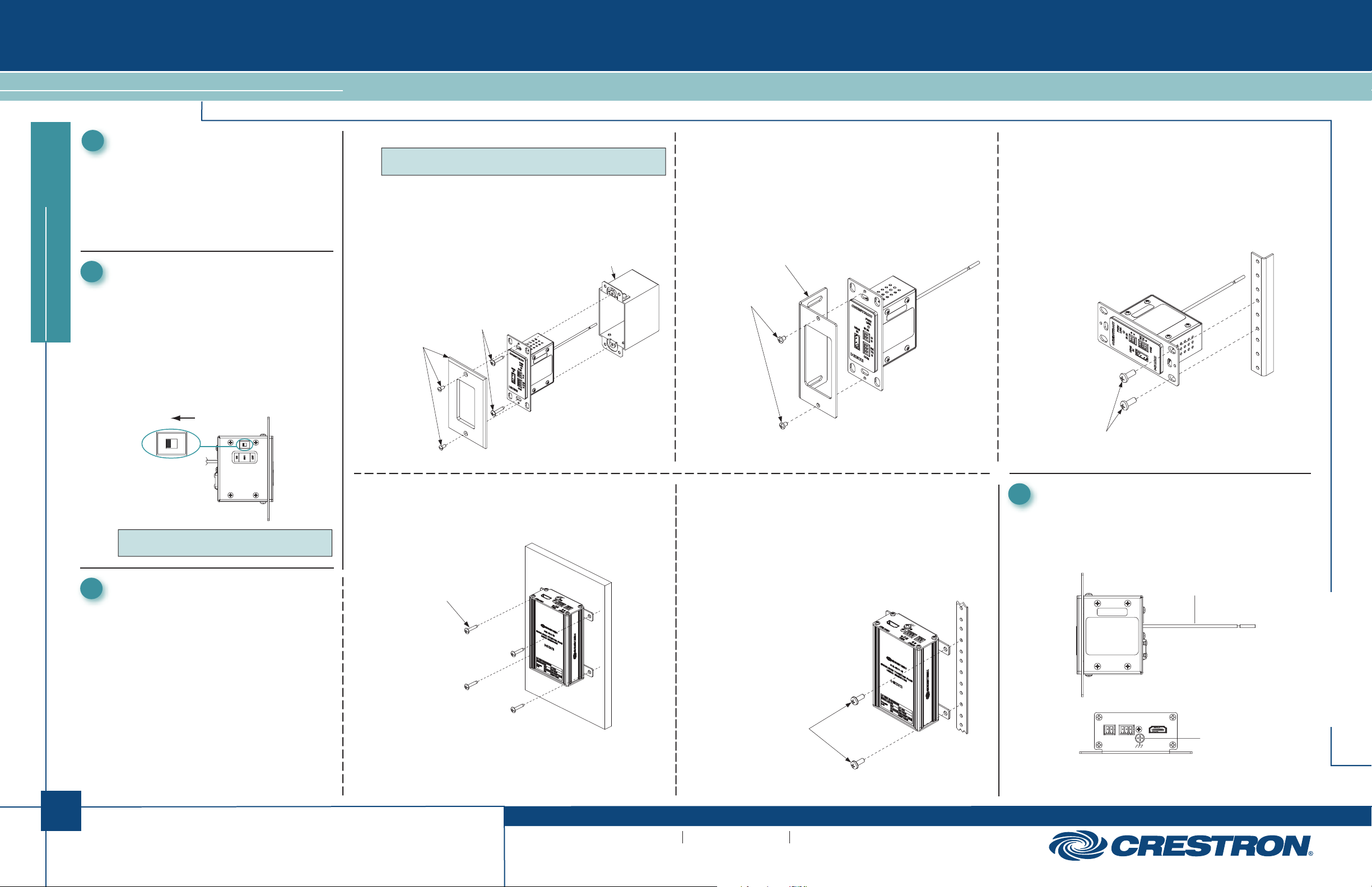
3
Mounting
Mount the HD-TX1-C and HD-RX1-C in any
of the following ways as appropriate for
your installation:
● (HD-TX1-C only) In a one-gang
electrical box
● On a flat surface
● On a rack rail
Mounting the HD-TX1-C in a One-Gang Electrical Box
Do the following:
1. Using two #6-32 x 3/4 inch combo head screws (supplied),
mount the HD-TX1-C in a one-gang electrical box.
2. Attach the desired decorator style faceplate (not supplied).
Mounting the HD-TX1-C on a Rack Rail
Mount the HD-TX1-C on the front or rear rail of a rack
as follows:
1. Position the HD-TX1-C horizontally so that the holes of
the left or right mounting flange align with the holes in the
rack (mounting of right mounting flange is shown below).
2. Secure the device to the rack using two rack mounting
screws (not supplied).
1
Introduction
1
The HD-EXT1-C provides an HDMI® extender
that consists of the HD-TX1-C transmitter
and HD-RX1-C receiver. Operating as a pair,
the HD-TX1-C and HD-RX1-C transmit
uncompressed digital high definition video,
audio, and control signals up to 330 feet
(100 meters) over a single DM-CBL-8G
shielded twisted pair (STP) cable.
Mounting the HD-TX1-C on a Flat Surface
Do the following in the order desired:
● Using two #6-32 x 3/16 inch Phillips head screws
(supplied), attach the transmitter to the mounting
bracket (supplied).
● Using the appropriate hardware (not supplied), attach
the bracket to a flat surface.
NOTE: The recommended depth of the electrical box
(not supplied) is a minimum of 2.5 inches.
Faceplate with
Hardware
(Not Supplied)
#6-32 x 3/4”
Combo Head
Screws
(Supplied)
Electrical Box
(Not Supplied)
#6-32 x 3/16”
Phillips Head Screws
(Supplied)
Mounting Bracket
(Supplied)
Rack Mounting Screws
(Not Supplied)
Mounting the HD-RX1-C on a Flat Surface
Using four mounting screws (not supplied), attach the
HD-RX1-C to a flat surface. Mounting of the HD-RX1-C on a
wall is shown below.
Mounting Screws (4)
(Not Supplied)
Mounting the HD-RX1-C on a Rack Rail
Mount the HD-RX1-C on the front or rear rail of a rack
as follows:
1. Position either the left or right mounting flanges of the
device so that the holes align with the holes in the rack
(mounting of right mounting flanges is shown below).
2. Secure the device to the rack using two rack mounting
screws (not supplied).
Rack Mounting Screws
(Not Supplied)
Connections
4
HD-TX1-C
Ground Wire
Connecting the HD-TX1-C and HD-RX1-C to Ground
Connect the ground wire on the HD-TX1-C and the
chassis ground lug on the HD-RX1-C to earth ground
(building steel).
HD-RX1-C
Ground Lug
COM
HDMI OUTIR OUT
G S
GTXRX
G
(Continued on following page)
Page 2

HD-EXT1-C
HDMI® over Shielded Twisted Pair Extender
Connections (Continued)
4
Connecting HDMI and Control Ports on the HD-TX1-C
Connecting the HDMI IN Port. Using an HDMI cable
(not supplied), connect the HDMI IN port to the HDMI
output port of the audio/video source.
Connecting the Control Ports. Connect the IR IN or
COM control port or both as follows:
● IR IN: Using an IR cable (not supplied), connect the
2-pin terminal block of the IR IN port to the IR output
port of the control system.
● COM (RS-232): Using a data communications cable
(not supplied), connect the 3-pin terminal block of the
COM port to the COM port of the control system.
quickstart guide
Connecting HDMI and Control Ports on the HD-RX1-C
Connecting the HDMI OUT Port. Using an HDMI cable
(not supplied), connect the HDMI OUT port to the HDMI
input port of the receiving device.
Connecting the Control Ports. Connect the IR OUT or
COM control port or both as follows:
● IR OUT: Using the Crestron
supplied), connect the 2-pin terminal block of the
IR OUT port to the IR input port of the device to
be controlled.
● COM (RS-232): Using a data communications cable
(not supplied), connect the 3-pin terminal block of
the
COM port to the COM port of the device to
be controlled.
Connecting the AV Port on the HD-TX1-C and HD-RX1-C
Connect the AV OUT port on the HD-TX1-C to the AV IN
port on the HD-RX1-C using either of the following
STP cables:
● DM-CBL-8G cable, which supports distances up to
330 feet (100 meters)
NOTE: For optimum performance and ESD (electrostatic
discharge) protection, it is recommended that DM-CBL-8G
cable be used.
● DM-CBL-D cable, which supports distances up to
200 feet (61 meters)
NOTE: The AV OUT port and the AV IN port accept power
over the STP cable. For additional information, refer to
“Connecting the 24 VDC Power Jack on the HD-TX1-C or
HD-RX1-C” at the top of the next column.
®
IRP2 emitter (not
AV
SOURCE
24V
0.75A
AV OUT
Connecting the 24 VDC Power Jack on the HD-TX1-C or HD-RX1-C
Only one 24 VDC power pack (supplied) powers both the HD-TX1-C
and HD-RX1-C. Connect the power pack to either the 24 VDC power
jack of the HD-TX1-C or HD-RX1-C as desired:
24V
0.75A
● If the power pack is connected to the HD-TX1-C, power is sent to the
PWR/
LINK
IR IN
HDMI
G
IN
S
RX
TX
G
COM
COM
G S
HDMI OUTIR OUT
GTXRX
G
CONTROL
SYSTEM
5
HD-RX1-C over the STP cable that connects the AV OUT port of the
HD-TX1-C to the AV IN port of the HD-RX1-C.
● If the power pack is connected to the HD-RX1-C, power is sent to the
HD-TX1-C over the STP cable that connects the AV IN port of the
HD-RX1-C to the AV OUT port of the HD-TX1-C.
LED Indicators
LEDs are provided on the HD-TX1-C and HD-RX1-C.
HD-TX1-C/
AV IN
AV OUT
PWR
24 V
0.75A
To HD-TX1-C
or
HD-RX1-C
POWER
PACK
HD-RX1-C COLOR DESCRIPTION
DISPLAY
AV IN
PWR
24 V
0.75A
HDMI
IN
IR IN
COM
Green
LED
PWR/
LINK
G
S
RX
TX
G
AV IN
Amber
LED
PWR/LINK LED
Amber LED
Green LED
PWR
24 V
0.75A
PWR
LED
24V
0.75A
AV OUT
INDICATOR
PWR/LINK
(HD-TX1-C
Only)
AV OUT/AV IN
PWR
(HD-RX1-C
Only)
Blinking green
Solid green
Solid amber
Off
Green
Blinking amber
Solid amber
Off
Green
Off
The HD-TX1-C is powered on but a link
is not established with the HD-RX1-C.
The HD-TX1-C is powered on and a
link is established with the HD-RX1-C;
however, HDMI video is not detected
on the HDMI input of the HD-RX1-C.
The HD-TX1-C is powered on, a link is
established with the HD-RX1-C, and
HDMI video is detected on the HDMI
input of the HD-RX1-C.
The HD-TX1-C is not powered on.
A link is established with the remote
HD-TX1-C/HD-RX1-C device.
Non-HDCP video is detected.
HDCP video is detected.
HDMI video is not detected.
The HD-RX1-C is powered on.
The HD-RX1-C is not powered on.
HD-EXT1-C
2
For Regulatory Compliance information, refer to the latest
version of Doc. 7024.
QUICKSTART DOC. 7023A (2028987) 11.10
www.crestron.com
©2010 Specifications subject to
change without notice.
888.273.7876 201.767.3400
Crestron is a registered trademark of Crestron Electronics, Inc.
HDMI is a trademark or registered trademark of HDMI Licensing LLC
in the United States and other countries.
 Loading...