

Page 1
HD-DA-2
Switch 1 Switch 2 Switch 3 Switch 4 Switch 5 Switch 6 Switch 7
HDMI IN OFF RCA OFF Copy HDMI 1 Audio EDID OFF OFF Copy HDMI 1 EDID (A/V) OFF OFF OFF
SPDIF Source ON OPTICAL ON Copy HDMI 2 Audio EDID ON OFF Copy HDMI 2 EDID (A/V) ON OFF OFF
LBR (DTS, AC3) or 2CH PCM OFF ON Copy HDMI 1 EDID (V) OFF ON OFF
2CH PCM Only ON ON Copy HDMI 2 EDID (V) ON ON OFF
Best Common (V) OFF OFF ON
Audio Input Source
SPDIF Source
Audio/Video EDID
Audio EDID
1-to-2 HDMI Distribution Amplifier & Audio Converter
Introduction
1
The HD-DA-2 provides a compact yet sophisticated HDMI splitter
solution with additional capabilities for converting HDMI audio to analog
and merging DVI or HDMI video with a separate digital audio signal.
Complete the following procedure to setup your HD-DA-2.
DIP Switch Overview
3
The HD-DA-2 is field programmable using seven DIP switches. The DIP
switches control the routing and EDID information that is relayed to the
source (e.g., Blu-ray player) from the device connected to the HD-DA-2
(e.g., HD display). DIP switches have two states, OFF (down) or ON (up).
Based on the AV configuration, a DIP switch setting may be ignored and
quickstart guide
is represented in this document as an X in place of the DIP switch
illustration. DIP switch number 8 is not used.
The HD-DA-2 must be power cycled for the settings to be applied.
Refer to the illustration below for a visual reference of the DIP switch
positions.
DIP switch in the OFF (down) position
DIP switch in the ON (up) position
DIP switch position is ignored
DIP Switch Description:
Switch 1 Audio Select: Allows you to choose between passing audio from the HDMI IN port or embedding audio from an SPDIF source.
Switch 2 Embedded Audio Source: If embedding audio from an SPDIF source (switch 1 = ON) audio will be received on the AUDIO IN OPTICAL or AUDIO IN SPDIF port.
Switch 3 & 4 Audio EDID Control: When used, these switch configurations control the audio EDID presented to the source. The primary EDID control (switches 5, 6 and 7) may override switches 3 and 4. The unit
may be set to copy the audio EDID from HDMI OUT 1 or HDMI OUT 2, or may force either of two pre-determined modes: LBR and 2CH PCM or 2CH PCM only.
Switch 5, 6 & 7 Primary EDID Control: These switches are used to control the EDID presented to the source. Certain switch configurations control audio and video EDID (indicated by (A/V) in the table). Other switch
configurations control video only (V). When using the (A/V) configurations, switches 3 and 4 are overridden. Using the (V) configurations, switches 3 and 4 control audio EDID. The user may elect to
copy the EDID from HDMI OUT 1 or HDMI OUT 2, or may elect to present to the source only the resolutions common to both outputs.
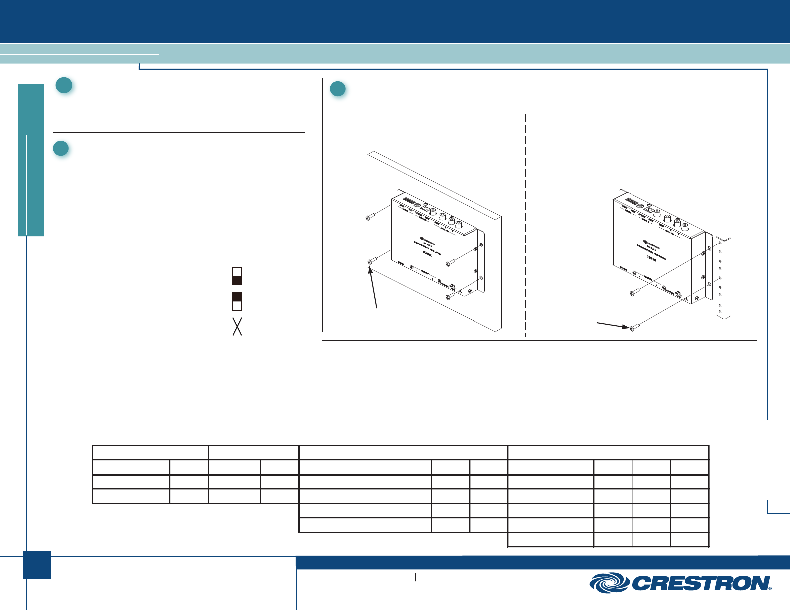
Mounting
2
Mount the HD-DA-2 onto a wall or rack as appropriate for your installation.
Wall Mounting
Using four mounting screws (not supplied), attach
the distribution amplifier to the wall as shown
below.
(4) Mounting Screws
(Not Supplied)
Rack Mounting
Mount the HD-DA-2 to the front or rear rail of a rack as follows:
1. Position the left or right mounting flange of the device so
the holes align with the holes in the rack (mounting with
the right flange is shown below).
2. Secure the device to the rack using two rack mounting
screws (not supplied).
(2) Rack Mounting Screws
(Not Supplied)
HD-DA-2
1
For Regulatory Compliance information, refer to the
latest version of Doc. 7043.
QUICKSTART DOC. 6960B (2027157) 08.10
www.crestron.com
©2010 Specifications subject to
change without notice.
888.273.7876 201.767.3400
All brand names, product names, and trademarks
are the property of their respective owners.
Page 2
HD-DA-2
567
8
8
8
1-to-2 HDMI Distribution Amplifier & Audio Converter
1
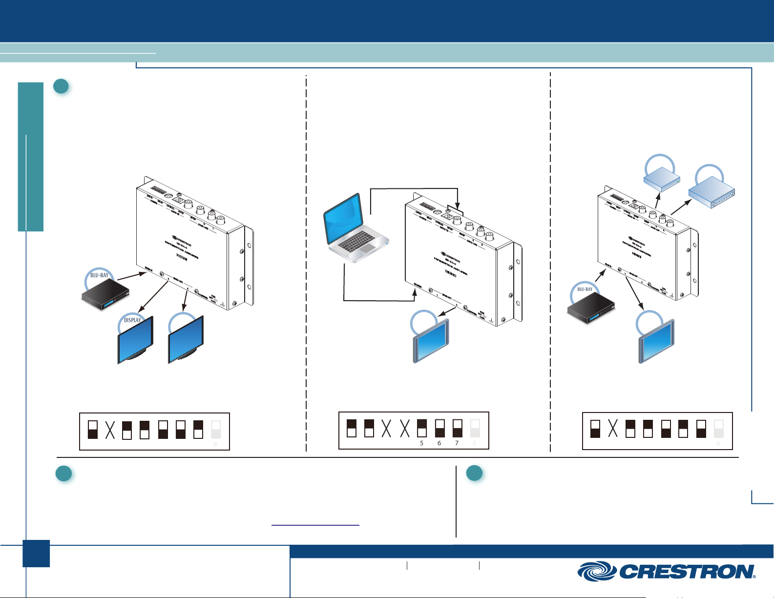
Applications
4
This section shows three common setups for the HD-DA-2. There are
many other applications that can be configured using the table on the
previous page.
Video Distribution
The HD-DA-2 can be used to distribute one HDMI video source to two
devices using their best common video EDID information. Connect the
video source to the HDMI IN port on the unit. Connect the devices
(e.g., displays) to the HDMI OUT 1 and HDMI OUT 2 ports.
quickstart guide
BLU-RAY
TMTM
DISPLAY
DISPLAY
Audio Embedding
The HD-DA-2 can be used to embed digital audio from DVI or
HDMI sources that do not transmit audio with the video. For
example, video from a computer via a DVI to HDMI conversion
cable. In this scenario digital audio must be sent to the
HD-DA-2 separately from the video.
To connect a computer to the HD-DA-2 make the following
connections. Connect the video output from the computer to the
HDMI IN port on the unit. Connect the digital audio out from the
computer to the AUDIO IN OPTICAL port on the HD-DA-2.
HD
DISPLAY
Audio Extraction
The HD-DA-2 can be used to extract audio from an
HDMI source and feed the audio to an AV receiver
and/or amplifier. Connect the video source to the
HDMI IN port on the unit. Connect the AV receiver
to the AUDIO OUT SPDIF port and/or the amplifier
to the AUDIO OUT R L ports.
AV
BLU-RAY
RECEIVER
TMTM
HD
DISPLAY
AMPLIFIER
To configure the DIP switches to send the best common video to
HDMI OUT 1 and HDMI OUT 2, and send 2CH PCM audio to both
displays, move the DIP switches to the positions shown in the following
illustration.
1 2 3 4 5 6 7
Rotary Switch
5
Use a small screwdriver to set the number of HDCP keys necessary for the setup. The switch allows up to 16 keys to
be set using the alpha numeric rotary switch (A - F corresponds to 10 - 15, and 0 corresponds to 16). The HD-DA-2
must be power cycled for the settings to be applied.
View the third party HDCP limits PDF on the Crestron website (www.crestron.com/hdcplimits) to calculate the
appropriate setting for the device.
2
For Regulatory Compliance information, refer to the
latest version of Doc. 7043.
QUICKSTART DOC. 6960B (2027157) 08.10
To configure the DIP switches to embed audio from the
OPTICAL port, receive video at HDMI IN and send audio and
video to HDMI OUT 2
shown in the following illustration
1 2 3 4
www.crestron.com
©2010 Specifications subject to
change without notice.
move the DIP switches to the positions
.
888.273.7876 201.767.3400
All brand names, product names, and trademarks
are the property of their respective owners.
Apply Power
6
After all connections have been made and the unit is properly grounded,
apply power to the HD-DA-2.
To configure the DIP switches to route audio to an
AV receiver and/or amplifier move the DIP switches
to the positions shown in the following illustration.
HD-DA-2
1 2 3 4 5 6 7
 Loading...