

Page 1
DM-TX-201-C
DigitalMedia 8G™ Shielded Twisted Pair (STP) Transmitter 201
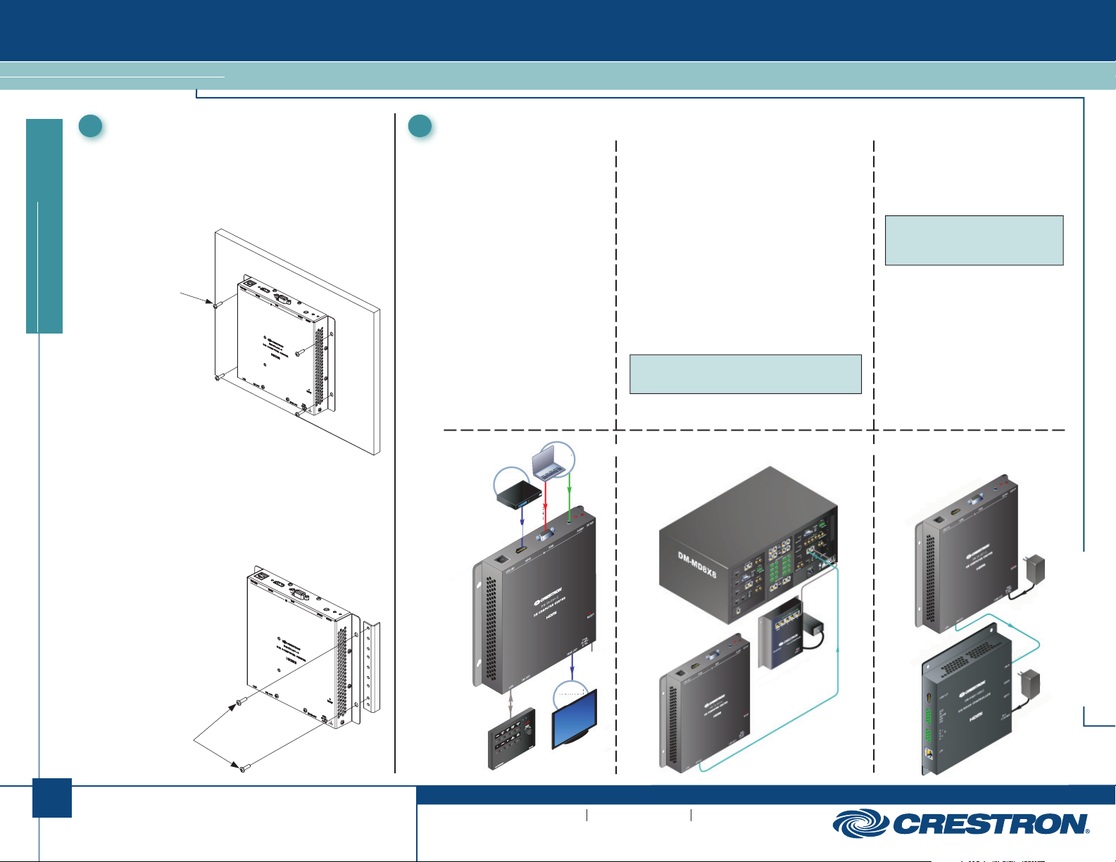
Mounting the DM-TX-201-C
1 2
Mount the transmitter onto a flat surface (such as a wall or
ceiling) or onto a rack rail as appropriate for your installation.
Mounting to a Flat Surface
Using four mounting screws (not included), mount the
transmitter on a flat surface. Mounting of the transmitter on
a wall is shown below.
Mounting Screws (4)
(Not Included)
quickstart guide
Rack Mounting
Mount the transmitter on the front or rear rail of a rack
as follows:
1. Position either the left or right mounting flange
of the device so that the holes align with the
holes in the rack (mounting of right flange is
shown below).
2. Secure the device
to the rack using
two rack mounting
screws (not included).
Connecting the DM-TX-201-C
Connecting the Top Ports
Connecting to a USB HID Device:
Connect the USB HID port to the
USB host interface of a computer
or other USB HID-compliant
host device.
Connecting to an HDMI® Audio/
Video Source: Using an HDMI
cable (not included), connect the
HDMI IN port to the HDMI output
port of the audio/video source.
Connecting to an RGB Video
Source: Using a VGA cable
(not included), connect the RGB IN
port to the RGB (VGA) or component
(YPbPr) video source.
Connecting to an Audio Source:
Using an unbalanced 3.5 mm TRS
mini phone jack cable (not included),
connect the AUDIO IN port to an
unbalanced audio source.
Audio, Video, LAN,
and Ground
Connections
DM-TX-201-C
BLU-RAY
LAPTOP
A
U
D
I
O
R
G
H
B
D
M
I
Connecting the Bottom Ports
Connecting to the LAN: Using an Ethernet cable
(not supplied), connect the 10BASE-T/100BASE-TX
LAN port to a local network device.
Connecting to a DigitalMedia (DM) Device:
Connect the DM OUT port of the transmitter to the
DM 8G STP input of a DM switcher, receiver/room
controller, or other DM device. If connecting to a
DM switcher, connect the transmitter to the DM IN
port of a DMC-C/DMC-C-DSP input card of
the switcher.
To connect the transmitter to the DM 8G STP input
of a DM device, use either of the following cables
(sold separately):
● DM-CBL-8G DigitalMedia cable, which supports
distances up to 330 feet (100 meters).
NOTE: For optimum performance and ESD
(electrostatic discharge) protection, it is
recommended that DM-CBL-8G cable be used.
● DM-CBL-D DigitalMedia cable, which supports
distances up to 200 feet (61 meters).
DM-TX-201-C Using Power over DM Via Connection to
DM Switcher (DM-MD8X8 Shown)
Connecting to an HDMI Audio/Video
Input Device: Using an HDMI cable
(not included), connect the HDMI OUT
port to the HDMI input port of the
receiving device.
Connecting the 24 VDC Power Jack:
NOTE: Connection to the 24 VDC
power jack is not required if the
transmitter is powered using power
over DM.
If required, connect the 24 VDC power
jack to the external power supply included
with the transmitter.
Connecting the Ground: Connect the
chassis ground lug to earth ground
(building steel).
DM-TX-201-C Direct Connection to
DM-RMC-100-C (External Power
Pack Required)
DM-TX-201-C
24 VDC
DM-TX-201-C
1
Rack Mounting
Screws
(Not Included)
For details, refer to the latest version of the DM-TX-201-C
Operations and Installation Guide, Doc. 6958.
QUICKSTART DOC. 6959A (2027156) 08.10
H
D
M
I
MONITOR
MPC-M10
www.crestron.com
©2010 Specifications subject to
change without notice.
GROUND
DM-TX-201-C
888.273.7876 201.767.3400
Crestron is a registered trademark of Crestron Electronics, Inc.
DigitalMedia 8G and Crestron Toolbox are trademarks of Crestron Electronics, Inc.
HDMI, the HDMI Logo, and High-Definition Multimedia Interface are trademarks or
registered trademarks of HDMI Licensing LLC in the United States and other countries.
CEN-SW-POE-5
DM 8G
DM-RMC-100-C
DM 8G
24 VDC
Page 2
DM-TX-201-C
DigitalMedia 8G™ Shielded Twisted Pair (STP) Transmitter 201
Setting the IP Address
3
Setup of the IP address of the DM-TX-201-C depends
on the way the transmitter is configured within the
DigitalMedia system:
● If the transmitter is connected to a receiver/room
controller, the transmitter uses its own configuration
settings. The transmitter ships with DHCP enabled;
however, the default IP address can be assigned by
holding down the SETUP button while the unit boots up.
The default IP address is 192.168.1.236. The default IP
address overwrites the current setting.
● If the transmitter is connected to a DM switcher,
the transmitter is automatically configured by the
quickstart guide
switcher.
If manual configuration of the IP address of the transmitter
is desired, use Crestron Toolbox™ to set the IP address.
2
For details, refer to the latest version of the DM-TX-201-C
Operations and Installation Guide, Doc. 6958.
QUICKSTART DOC. 6959A (2027156) 08.10
www.crestron.com
©2010 Specifications subject to
change without notice.
888.273.7876 201.767.3400
Crestron is a registered trademark of Crestron Electronics, Inc.
DigitalMedia 8G and Crestron Toolbox are trademarks of Crestron Electronics, Inc.
HDMI, the HDMI Logo, and High-Definition Multimedia Interface are trademarks or
registered trademarks of HDMI Licensing LLC in the United States and other countries.
DM-TX-201-C
 Loading...