

Page 1

Crestron DM-MD8X8/16X16/32X32
DigitalMedia™ Switchers
Operations Guide
Page 2
This document was prepared and written by the Technical Documentation department at:
Crestron Electronics, Inc.
15 Volvo Drive
Rockleigh, NJ 07647
1-888-CRESTRON
Important Safety Instructions
• Read these instructions.
• Keep these instructions.
• Heed all warnings.
• Follow all instructions.
• Do not use this apparatus near water.
• Clean only with dry cloth.
• Do not block any ventilation openings. Install in accordance
with the manufacturer's instructions.
• Do not install near any heat sources such as radiators, heat
registers, stoves, or other apparatus (including amplifiers) that
produce heat.
• Do not defeat the safety purpose of the polarized or groundingtype plug. A polarized plug has two blades with one wider than
the other. A grounding-type plug has two blades and a third
grounding prong. The wide blade or the third prong are
provided for your safety. If the provided plug does not fit into
your outlet, consult an electrician for replacement of the
obsolete outlet.
• Protect the power cord from being walked on or pinched
particularly at plugs, convenience receptacles, and the point
where they exit from the apparatus.
• Only use attachments/accessories specified by the
manufacturer.
• Use only with the cart, stand, tripod, bracket or
table specified by the manufacturer or sold with
the apparatus. When a cart is used, use caution
when moving the cart/apparatus combination to
avoid injury from tip-over.
• Unplug this apparatus during lightning storms or when unused
for long periods of time.
• Refer all servicing to qualified service personnel. Servicing is
required when the apparatus has been damaged in any way,
such as power-supply cord or plug is damaged, liquid has been
spilled or objects have fallen into the apparatus, the apparatus
has been exposed to rain or moisture, does not operate
normally, or has been dropped.
• Disconnect power prior to connecting or disconnecting
equipment.
• Do not install in direct sunlight.
• The apparatus must be installed in a way that the power cord
can be removed either from the wall outlet or from the device
itself in order to disconnect the mains power.
• Prevent foreign objects from entering the device.
WARNING:
TO REDUCE THE RISK OF FIRE OR ELECTRIC SHOCK,
DO NOT EXPOSE THIS APPARATUS TO RAIN OR
MOISTURE. THE APPARATUS SHALL NOT BE
EXPOSED TO DRIPPING OR SPLA SHING. OBJECTS
FILLED WITH LIQUIDS, SUCH AS VASES, SHOULD
NOT BE PLACED ON THE APPARATUS.
WARNING:
TO PREVENT ELECTRIC SHOCK, DO NOT REMOVE
COVER. THERE ARE NO USER SERVICEABLE PARTS
INSIDE. ONLY QUALIFIED SERVICE PERSONNEL
SHOULD PERFORM SERVICE.
CAUTION
RISK OF ELECTRIC SHOCK
DO NOT OPEN
AVIS: RISQUE DE CHOC ELECTRIQUE NE PAS OUVRIR
The lightning flash with arrowhead symbol, within an
equilateral triangle, is intended to alert the user to the
presence of uninsulated “dangerous voltage” within the
product's enclosure that may be of sufficient magnitude to
constitute a risk of electric shock to persons.
The exclamation point within an equilateral triangle is
intended to alert the user to the presence of important
operating and maintenance (servicing) ins tructions in the
literature accompanying the appliance.
WARNING:
THIS IS AN APPARATUS WITH CLASS I
CONSTRUCTION. IT SHALL BE CONNECTED TO AN
ELECTRICAL OUTLET WITH AN EARTHING GROUND
TERMINAL.
IMPORTANT:
The DM-MD8X8, DM-MD16X16, and DM-MD32X32
can be used with Class 2 output wiring.
This device includes an aggregation of separate independent works that are each generally copyrighted by Crestron Electronics, Inc., with all rights
reserved. One of those independent works, Linux Bridge Project, is copyrighted under the GNU GENERAL PUBLIC LICENSE, Version2,
reproduced in “GNU General Public License” on page 186, where the corresponding source code is available at: ftp://ftp.crestron.com/gpl.
All brand names, product names and trademarks are the property of their respective owners.
©2010 Crestron Electronics, Inc.
Page 3
Regulatory Compliance
As of the date of manufacture, this unit has been tested and found to comply with specifications for CE marking
and standards per EMC and Radiocommunications Compliance Labelling.
Federal Communications Commission (FCC) Compliance Statement
This device complies with part 15 of the FCC Rules. Operation is subject to the following conditions:
(1) This device may not cause harmful interference and (2) this device must accept any interference received,
including interference that may cause undesired operation.
CAUTION: Changes or modifications not expressly approved by the manufacturer responsible for compliance
could void the user’s authority to operate the equipment.
NOTE: This equipment has been tested and found to comply with the limits for a Class B digital device,
pursuant to part 15 of the FCC Rules. These limits are designed to provide reasonable protection against harmful
interference in a residential installation. This equipment generates, uses and can radiate radio frequency energy
and, if not installed and used in accordance with the instructions, may cause harmful interference to radio
communications. However, there is no guarantee that interference will not occur in a particular installation. If
this equipment does cause harmful interference to radio or television reception, which can be determined by
turning the equipment off and on, the user is encouraged to try to correct the interference by one or more of the
following measures:
Reorient or relocate the receiving antenna
Increase the separation between the equipment and receiver
Connect the equipment into an outlet on a circuit different from that to which the receiver is connected
Consult the dealer or an experienced radio/TV technician for help
Industry Canada (IC) Compliance Statement
This Class B digital apparatus complies with Canadian ICES-003.
Cet appareil numérique de la classe B est conforme à la norme NMB-003 du Canada.
Page 4

Page 5

Crestron DM-MD8X8/16X16/32X32 DigitalMedia™ Switchers
Contents
DigitalMedia™ Switchers: DM-MD8X8/16X16/32X32 1
Introduction ...............................................................................................................................1
Features and Functions................................................................................................1
Applications.................................................................................................................6
Internal Block Diagrams..............................................................................................7
Specifications ..............................................................................................................9
Physical Description..................................................................................................15
Setup........................................................................................................................................28
DigitalMedia Wiring .................................................................................................28
HDCP Signal Path.....................................................................................................30
Ethernet Setup ...........................................................................................................32
Identity Code.............................................................................................................32
Installation.................................................................................................................33
Hardware Hookup .....................................................................................................34
Configuration...........................................................................................................................41
Inputs.........................................................................................................................42
Outputs......................................................................................................................43
Network.....................................................................................................................44
Control.......................................................................................................................49
Message Log..............................................................................................................53
Commission System..................................................................................................54
Programming Software............................................................................................................61
Earliest Version Software Requirements for the PC .................................................61
Programming with SIMPL Windows........................................................................61
Example Program......................................................................................................65
Uploading and Upgrading........................................................................................................66
Establishing Communication.....................................................................................66
Programs and Firmware ............................................................................................67
Program Checks ........................................................................................................67
DM Tool....................................................................................................................68
Operation.................................................................................................................................69
Operating Modes.......................................................................................................69
Route Mode ...............................................................................................................69
View Mode.................................................................................................................70
Info Mode..................................................................................................................71
Problem Solving......................................................................................................................72
Troubleshooting.........................................................................................................72
Check Network Wiring..............................................................................................73
Reference Documents................................................................................................74
Further Inquiries........................................................................................................74
Future Updates ..........................................................................................................74
Appendix A: Hardware Hookup for DM Cards......................................................................75
Input Cards................................................................................................................75
Output Connections ...................................................................................................87
Appendix B: Input Card Configuration..................................................................................90
Operations Guide – DOC. 6755C Contents • i
Page 6

DigitalMedia™ Switchers Crestron DM-MD8X8/16X16/32X32
DMC-CAT ................................................................................................................91
DMC-CAT-DSP........................................................................................................99
DMC-DVI ...............................................................................................................107
DMC-F....................................................................................................................115
DMC-F-DSP............................................................................................................121
DMC-HD.................................................................................................................127
DMC-HD-DSP........................................................................................................135
DMC-SDI................................................................................................................143
DMC-VID4 .............................................................................................................147
DMC-VID-BNC......................................................................................................154
DMC-VID-RCA-A..................................................................................................161
DMC-VID-RCA-D..................................................................................................168
Appendix C: Output Configuration .......................................................................................175
Glossary.................................................................................................................................180
Return and Warranty Policies................................................................................................184
Merchandise Returns / Repair Service ....................................................................184
CRESTRON Limited Warranty...............................................................................184
Trademark Information ...........................................................................................185
GNU General Public License ................................................................................................186
ii • Contents Operations Guide – DOC. 6755C
Page 7

Crestron DM-MD8X8/16X16/32X32 DigitalMedia™ Switchers
DigitalMedia™ Switchers:
DM-MD8X8/16X16/32X32
Introduction
Crestron® DigitalMedia™ (DM) switchers provide the foundation for a comple te
DigitalMedia system, delivering a true high-definition multi-room AV signal routing
solution that is flexible and installer-friendly. The DM-MD8X8, DM-MD16X16, and
DM-MD32X32 afford low-latency switching and pure, lossless d istribution of
HDMI™ and other signals to support the latest Blu-ray Disc™ players, HDTV
receivers, digital media servers, computers, and other AV devices.
Features and Functions
• Three Models: DM-MD8X8 (eight inputs, eight outputs), DM-MD16X16
(16 inputs, 16 outputs), and DM-MD32X32 (32 inputs, 32 outputs)
• Distributes uncompressed digital video and audio over twisted-pair wire or
fiber
• Supports HDMI with Deep Color and 7.1 channel HD lossless audio
• Supports video resolutions up to WUXGA 1920x1200 and HD 1080p60
• Allows cable length to 450 feet (137 m) using DigitalMedia cable, 1000
feet (300 m) using CresFiber
• Supports up to eight (DM-MD8X8) . 16 (DM - MD16X16), or
32 (DM-MD32X32) DM receivers and room controllers with easy
expansion for more outputs
• Configurable inputs support a complete range of digital and analog signal
types
• Detects and displays detailed video and audio input information
• QuickSwitch HD technology achieves low-latency HDMI switching
• Manages HDCP digital rights management for every device
• Performs automatic AV signal format management via EDID
• Enables device control via CEC
• Distributes USB HID mouse and keyboard signals
• Allows full audio and USB breakaway switching
• Integrates with analog audio distribution systems
• Enables simultaneous output of stereo and surround sound audio
• Includes integrated Ethernet switch with Gigabit LAN port
®
(Continued on following page)
Operations Guide – DOC. 6755C DigitalMedia™ Switchers: DM-MD8X8/16X16/32X32 • 1
Page 8

DigitalMedia™ Switchers Crestron DM-MD8X8/16X16/32X32
p
)
Features and Functions
(Continued)
• Includes built-in power distribution for DM transmitters, repeaters, and
room controllers
• Provides easy setup and diagnostics tools via front panel or software
• 19-inch rack-mountable (DM-MD8X8: 4-space, DM-MD16X16: 7-space,
DM-MD32X32: 14-s
DM switchers are field-configurable to handle up to 32 AV so urces of virtually any
type. The outputs of the DM-MD32X32 are fiel d-c on fi g ur able to provide up to 32
DM room outputs and/or HDMI outputs in a single chassis, with expansion
capability possible for up to 160 outputs using multiple chassis. The outputs of the
DM-MD16X16 are factory-configurable to provide up to 16 DM room outputs
and/or HDMI outputs in a single chassis, with expansion capability possible for up to
80 outputs using multiple chassis. The outputs of the DM-MD8X8 are
field-configurable to provide up to eight DM room outputs and/or HDMI outputs in a
single chassis, with expansion capability possible for up to 40 outputs using multiple
DM-MD8X8 chassis.
A full selection of DM switcher input cards, DM transmitters, DM receivers, and
DM room controllers provides extensive connectivity throughout the home or office,
supporting a complete range of analog and digital signal types — all through one
switcher. User-friendly setup and troubleshooting tools are provided through the
front panel, or via Crestron Toolbox™ software, to simplify setup.
ace
DigitalMedia Switchers are part of a High Definition Audio-Video distribution
system that allows virtually any mix of AV sources to be distributed throughout the
home from a centralized rack location using DigitalMedia.
DigitalMedia™
Creating a professional HD AV distribution system means handling the challenges
that come with HDMI. HDMI is the new standard for interfacing high-definition AV
equipment, but despite its many benefits, it was not developed with multi-room
distribution in mind. Crestron has developed DigitalMedia, the first complete HD
AV distribution system that allows virtually any mix of HD AV sources to be
distributed throughout the home from a centralized rack location.
DigitalMedia distributes uncompressed digital video and audio signals over a choice
of shielded twisted-pair copper wire or multi-mode fiber. DigitalMedia manages all
of the different signals and devices, matching each source's output to the capabilities
of the selected display(s) without using scaling or compression. Every signal is
preserved in its native video resolution and audio format, ensuring a pure, lossless
signal path throughout.
Integrated Ethernet and USB HID distribution allows computers and media servers,
to be installed out-of-sight and accessed from anywhere in the house. Crestron
control is also built-in for controlling the displays and other room devices without
additional wiring.
Modular Architecture
DM switchers feature a modular architecture with eight (DM-MD8X8),
16 (DM-MD16X16), or 32 (DM-MD32X32) input card slots and two output card
slots with two, four, six, or eight outputs. Each input card slot on a DM switcher is
field-installable, allowing for easy and flexible system configuration with the ability
to make changes to the system as needs change.
2 • DigitalMedia™ Switchers: DM-MD8X8/16X16/32X32 Operations Guide – DOC. 6755C
Page 9

Crestron DM-MD8X8/16X16/32X32 DigitalMedia™ Switchers
A wide selection of DM input cards are offered to support a complete range of digital
and analog AV signal types. Depending on the switcher, up to eight output cards
may be installed to feed up to eight (DM-MD8X8), 16 (DM-MD16X16), or
32 (DM-MD32X32) DM Receivers/Room Controllers using either DigitalMedia
(DM) Cable or CresFiber. DigitalMedia allows for cable lengths up to 450 feet
(137 m) using DM cable, or 1000 feet (300 m) using CresFiber. HDMI outputs are
also available for direct connection to centralized audio processors and video
monitors.
Output Expansion
An HDMI loop back output is provided on every input card to allow the inputs of up
to five DM switchers to be daisy-chained, enabling the configuration of very large
distribution systems with many DM and HDMI outputs.
Versatile Audio Routing
HDMI is the key to handling all the latest 7.1 surround sound formats like Dolby®
TrueHD and DTS-HD Master Audio. Great for your high-end home theater, but how
do you share that same source with other audio zones in the house?
DigitalMedia allows for the simultaneous distribution of multi-channel surround
sound (i.e. Dolby TrueHD and DTS-HD Master Audio) and two-channel stereo
signals from the same HDMI source. Equipped with a DMC-HD-DSP, DMC-F-DSP,
or DMC-CAT-DSP input card (all sold separately), the DM switcher employs
onboard DSP processing to derive a stereo down-mix from the original multi-channel
signal. Both signals can be routed separately or simultaneously from any of the
switcher’s DM outputs, allowing either signal to be selected for output at each DM
receiver location.
The switcher also converts the digital stereo signal to analog to enable sharing with
every other room in the house via an AAE, CNX-P AD 8 A (b ot h sold separately), or
other multi-room audio distribution system. DM switchers also allow surround sound
processors and amplifiers to be located centrally instead of at the display location
using optional local HDMI outputs.
Computer Compatibility
Besides handling every available HDTV format supp orted by HDMI, DigitalMedia
also supports the distribution of DVI, DisplayPort multimode*, and RGB computer
signals, and is fully compatible with DVI computer monitors up to 1920 x 1200
WUXGA.
* DisplayPort multimode connectivity is supported via an HDMI or DVI input port using a suitable
adapter or interface cable (not included).
Built-in Ethernet Switch
In addition to transporting digital video and audio, DigitalMedia can also ex tend
10/100 Ethernet out to each display and source device via DM room controllers and
select DM transmitters, providing high-speed connectivity for any room device that
requires a LAN connection. Its Gigabit Ethernet connection to the external LAN
helps maximize bandwidth for each network port. Ethernet is also utilized internally
by the Crestron control bus to manage all of the DM devices in the system and
provide display control in each room.
USB HID Switch
DigitalMedia lets you centralize all HD sources – not just television receivers and
DVD changers, but also media servers and computers. Built-in USB HID (Human
Operations Guide – DOC. 6755C DigitalMedia™ Switchers: DM-MD8X8/16X16/32X32 • 3
Page 10

DigitalMedia™ Switchers Crestron DM-MD8X8/16X16/32X32
Interface Device) signal routing allows USB HID compatible keyboards and mice to
be connected at a remote display location, conference table or presentation lectern,
extending their signals through to the centralized equipment via USB HID ports
provided on select switcher input cards.
EDID Format Management
Using HDMI provides a variety of video and audio formats to keep track of, and
chances are not every device in a system supports all of the same formats. In a
typical one-room system, HDMI attempts to resolve this confusion using EDID
(Extended Display Identificati on Dat a ) . When two HDMI devices are connected
together, the receiving device (a display or surround sound processor) uses EDID to
announce its format capabilities to the source device (a TV tuner or video player),
which in turn configures itself to output the most effective format that both devices
can support.
However, serious conflicts arise in a facility filled with different displays and audio
systems. For instance, the Blu-ray player that is feeding a 1080p projector in the
theater may restrict itself to a lower resolution, or even shut off completely, if
someone decides to view the same signal on the 20” TV in the kitchen. And, instead
of listening to a 7.1 Dolby TrueHD format supported by a high-end theater sound
system, the listening experience may be limited to Dolby 5.1, or even stereo sound.
DM switchers use EDID to prevent such conflicts, assessing the formats supported
by each system device, and then allowing the installer to assign compatible devices
in logical arrangements. Conflicting combinations can be prohibited so only the
optimum signal formats get delivered to each display and audio system in the house.
All DigitalMedia wiring is also tested for integrity and bandwidth capability,
optimizing system operation by instructing sources to output only resolutions and
formats that the wiring can reliably handle.
QuickSwitch HD Technology
Crestron QuickSwitch HD technology minimizes the switching latency that plagues
typical HDMI switchers. As the move to digital takes hold, more and more movie
studios and television service providers are using HDCP (High-bandwidth Digital
Content Protection) to protect their DVDs, Blu-ray Discs, and broadcast signals
against unauthorized copying. Viewing the HDCP encrypted content in its full high-
definition format requires a source device to “authenticate” each display and signal
processor in the system through an HDMI connection before delivering an output
signal. Normally the authentication process occurs every time any HDMI signal is
switched, causing a complete loss of signal for up to 15 seconds whenever a new
source or display is selected anywhere in the system.
QuickSwitch HD technology achieve s very fast switching of HDMI signals by
maintaining a constant HDCP connection with each HDMI device in the system,
eliminating the need to re-authenticate each time a different source is selected.
HDCP Key Management
Another aspect to HDCP is its use of “keys” to manage the handshaking that occurs
between any two devices. Every HDMI source device has a limit to how many
downstream devices it can support, determined by the number of HDCP keys it has
available. Rarely is that limit advertised or specified by the manufacturer or service
provider, so connect too many displays or processors and the source will simply stop
outputting a signal without warning.
To prevent such surprises, DM switchers test the HDCP limits of each HDMI source,
allowing the installer to configure the system around any limitations, or substitute a
different component.
4 • DigitalMedia™ Switchers: DM-MD8X8/16X16/32X32 Operations Guide – DOC. 6755C
Page 11

Crestron DM-MD8X8/16X16/32X32 DigitalMedia™ Switchers
CEC Embedded Device Control
The primary objective of every Crestron system is to enable precisely the control
desired for a seamless user experience. DigitalMedia provides an alternative to
conventional IR and RS-232 device control by harnessing the CEC (Consumer
Electronics Control) signal embedded in HDMI. Through its connection to the
control system, the DM switcher provides a gateway for controlling many devices
right through their HDMI connections, potentially eliminating the need for any
dedicated control wires or IR probes. Through proper CEC signal management,
DigitalMedia allows you to take control of each device as you like.
Easy Setup
Via the front panel or using Crestron Toolbox software, every step of the
DM switcher’s setup process is designed to be quick and easy, configuring inputs
and outputs automatically while letting the installer make intelligent design decisions
along the way. The switcher tests and measures the length of each DM cable,
automatically making the appropriate calibrations for optimal signal transmission to
every room. With DigitalMedia, an entire switcher system can be commissioned in
as little as 15 minutes.
Operations Guide – DOC. 6755C DigitalMedia™ Switchers: DM-MD8X8/16X16/32X32 • 5
Page 12
DigitalMedia™ Switchers Crestron DM-MD8X8/16X16/32X32
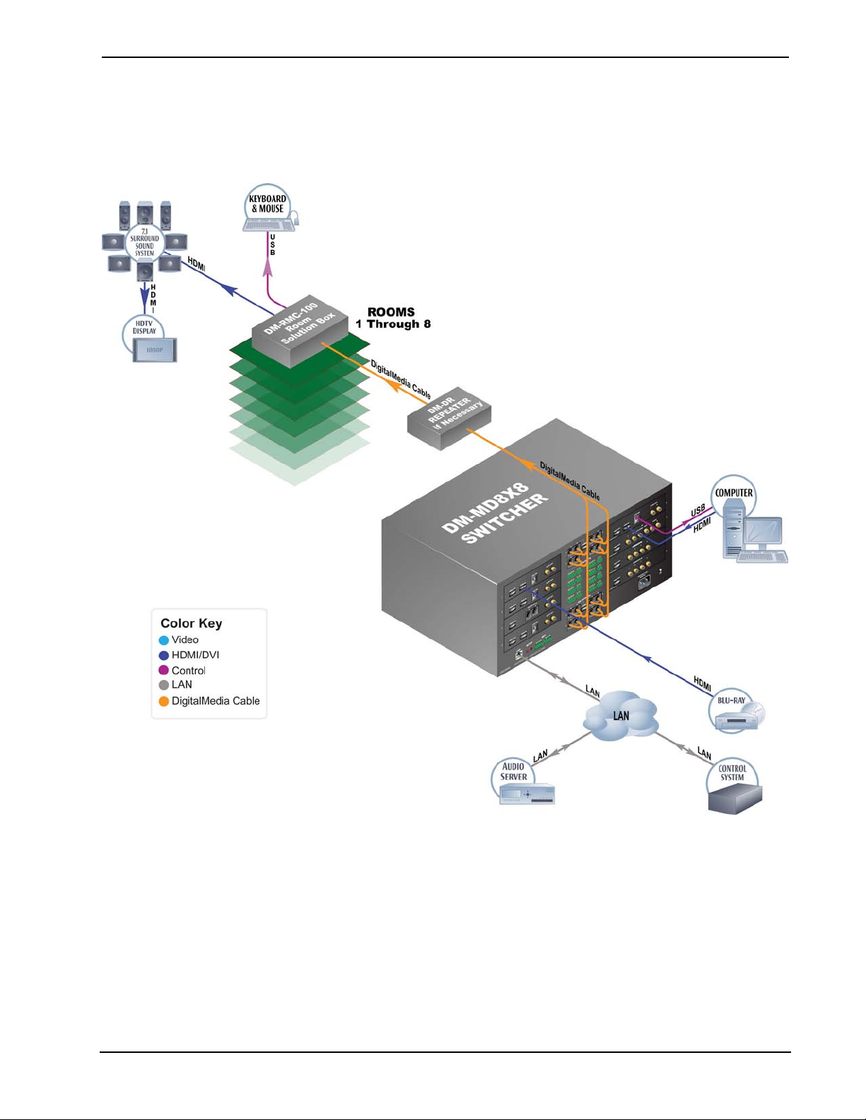
Applications
The following diagram shows a DM-MD8X8 in a lecture hall application.
DM-MD8X8 in a Lecture Hall Application
6 • DigitalMedia™ Switchers: DM-MD8X8/16X16/32X32 Operations Guide – DOC. 6755C
Page 13
Crestron DM-MD8X8/16X16/32X32 DigitalMedia™ Switchers
Internal Block Diagrams
The following diagrams represent the switching abilities of the DM switchers.
Internal Block Diagram of the DM-MD8X8
DM-MD8X8 Internal Block Diagram
From Input
cards (x8)
HDMI
From Input
car d s (x8 )
In put Card
(typical)
To/From DM-MD8X8 CPU To/From external LAN port
Stereo
Audio
10/100
ENET
To/From
Input cards (x 8)
Digital Video/Audio Switch
3.4Gb ps bandwidth
1
8
St ere o Au di o S wit c h
1
8
M a na ged Et he rnet S witc h
1
9
To O u t p u t
Modules (x8)
1
8
To O u t p u t
Modules (x8)
1
8
To/From Output
Modules (x8)
1
9
Gbit
ENET
HDMI (x4)
Ster eo
Audio (x4)
10/100
ENET (x4)
Internal Block Diagram of the DM-MD16X16
DM-MD16X16 Internal Block Diagram
From Input
cards (x16)
Digital Video/Audio Switch
3.4Gbps bandwidth
1
To Output
Modules (x16)
1
Output
Module
(typical)
HDMI
16
From Input
cards (x16)
Input Card
(typical)
To/From DM-MD16X16 CPU To/From external LAN port
Stereo
Audio
10/100
ENET
To/From
Input cards
(x16)
Stereo Audio Switch
1
16
Managed Ethernet Switch
1
17
16
To Output
Modules (x16)
1
16
To/From Output
Modules (x16)
1
17
Gbit
ENET
HDMI (x8)
Stereo
Audio (x8)
10/100
ENET (x8)
Output
Module
(typical)
Operations Guide – DOC. 6755C DigitalMedia™ Switchers: DM-MD8X8/16X16/32X32 • 7
Page 14
DigitalMedia™ Switchers Crestron DM-MD8X8/16X16/32X32
Internal Block Diagram of the DM-MD32X32
DM-MD32X32 Internal Block Diagram
From Input
cards (x32)
HDMI
From Input
cards (x32)
Input Card
(typical)
To/From DM-MD32X32 CPU To/From external LAN port
Stereo
Audio
10/100
ENET
To/From
Input cards
(x32)
Digital Video/Audio Switch
3.4Gbps bandwidth
1
32
Stereo Audio Switch
1
32
Managed Ethernet Switch
1
33
To Output
Modules (x32)
1
32
To Output
Modules (x32)
1
32
To/From Output
Modules (x32)
1
33
Gbit
ENET
HDMI (x16)
Stereo
Audio (x16)
10/100
ENET (x16)
Output
Module
(typical)
8 • DigitalMedia™ Switchers: DM-MD8X8/16X16/32X32 Operations Guide – DOC. 6755C
Page 15

Crestron DM-MD8X8/16X16/32X32 DigitalMedia™ Switchers
Specifications
Specifications for DM switchers are listed in the following table.
DM Switcher Specifications
SPECIFICATION DETAILS
Video
Switcher
Input Signal Types
Output Signal Types
Formats
(determined by input cards)
Input Resolutions
HDMI/DVI, Progressive
DM-MD8X8:
8x8 digital matrix, modular input/output cards,
Crestron QuickSwitch HD
DM-MD16X16:
16x16 digital matrix, modular input/output
cards, Crestron QuickSwitch HD
DM-MD32X32:
32x32 digital matrix, modular input/output
cards, Crestron QuickSwitch HD
Configurable via modular plug-in cards
supporting HDMI, DisplayPort Multimode
DVI, SDI, RGB, component (YP
(Y/C), composite video, DM CAT, and DM
fiber
Configurable via plug-in cards (factoryinstalled on DM-MD16X16) supporting DM
CAT, DM fiber, and HDMI (All input cards also
include HDMI loop back outputs)
HDMI with Deep Color, DVI, HDCP v.1.2
content protection support, SD-SDI, HD-SDI,
3G-SDI, RGBHV up to UXGA/WUXGA, HDTV
up to 1080p60, NTSC or PAL
640x480@60Hz, 720x480@60Hz (480p),
720x576@50Hz (576p), 800x600@60Hz,
848x480@60Hz, 852x480@60Hz,
854x480@60Hz, 1024x768@60Hz,
1024x852@60Hz, 1024x1024@60Hz,
1280x720@50Hz (720p50), 1280x720@60Hz
(720p60), 1280x768@60Hz,
1280x800@60Hz, 1280x960@60Hz,
1280x1024@60Hz, 1360x768@60Hz,
1365x1024@60Hz, 1366x768@60Hz,
1400x1050@60Hz, 1440x900@60Hz,
1600x900@60Hz, 1600x1200@60Hz,
1680x1050@60Hz, 1920x1080@24Hz
(1080p24), 1920x1080@25Hz (1080p25),
1920x1080@50Hz (1080p50),
1920x1080@60Hz (1080p60),
1920x1200@60Hz, 2048x1080@24Hz,
2048x1152@60Hz, plus any other resolution
allowed by HDMI up to 165MHz pixel clock
bPr
1
,
), S-video
(Continued on following page)
Operations Guide – DOC. 6755C DigitalMedia™ Switchers: DM-MD8X8/16X16/32X32 • 9
Page 16

DigitalMedia™ Switchers Crestron DM-MD8X8/16X16/32X32
DM Switcher Specifications (Continued)
SPECIFICATION DETAILS
Video (continued)
Input Resolutions
HDMI/DVI, Interlaced
RGB
Component
Composite and S-video
SDI
Output Resolutions
Backplane Data Rate
720x480@30Hz (480i), 720x576@25Hz
(576i), 1920x1080@25Hz (1080i25),
1920x1080@30Hz (1080i30), plus any other
resolution allowed by HDMI up to 165MHz
pixel clock
640x480@60Hz, 720x480@60Hz (480p),
720x576@50Hz (576p), 800x600@60Hz,
848x480@60Hz, 1024x768@60Hz,
1280x720@50Hz (720p50), 1280x720@60Hz
(720p60), 1280x768@60Hz,
1280x800@60Hz, 1280x960@60Hz,
1280x1024@60Hz, 1360x768@60Hz,
1366x768@60Hz, 1400x1050@60Hz,
1440x900@60Hz, 1600x1200@60Hz,
1680x1050@60Hz, 1920x1080@24Hz
(1080p24), 1920x1080@50Hz (1080p50),
1920x1080@60Hz (1080p60),
1920x1200@60Hz, 2048x1080@24Hz,
2048x1152@60Hz
480i, 576i, 480p, 576p, 720p50, 720p60,
1080i25 (1125 lines), 1080i30, 1080p30,
1080p50 (1125 lines), 1080p60
480i, 576i
SMPTE 425M (3G-SDI) 4:2:2 Colorspace:
1920x1080@50Hz (1080p50),
1920x1080@60Hz (1080p60);
SMPTE 425M (3G-SDI) 4:4:4 Colorspace:
1280x720@24Hz (720p24), 1280x720@25Hz
(720p25), 1280x720@50Hz (720p50),
1280x720@60Hz (720p60),
1920x1080@24Hz (1080p24),
1920x1080@25Hz (1080p25),
1920x1080@30Hz (1080p30),
1920x1080@50Hz (1080i50 or 1080sF25),
1920x1080@60Hz (1080i60 or 1080sF30);
SMPTE 260M (HD-SDI): 1920x1035@60Hz
(1035i60);
SMPTE 295M (HD-SDI): 1920x1080@50Hz
(1080i50);
SMPTE 274M (HD-SDI): 1920x1080@24Hz
(1080p24), 1920x1080@24Hz (1080sF24),
1920x1080@25Hz (1080p25),
1920x1080@30Hz (1080p30),
1920x1080@50Hz (1080i50 or 1080sF25),
1920x1080@60Hz (1080i60 or 1080sF30);
SMPTE 296M (HD-SDI): 1280x720@24Hz
(720p24), 1280x720@25Hz (720p25),
1280x720@30Hz (720p30), 1280x720@50Hz
(720p50), 1280x720@60Hz (720p60);
SMPTE 259M-C (SD-SDI): 720x480@59.94
(NTSC), 720x576@50i (PAL)
Matched to inputs
12.5 Gbps
(Continued on following page)
10 • DigitalMedia™ Switchers: DM-MD8X8/16X16/32X32 Operations Guide – DOC. 6755C
Page 17
Crestron DM-MD8X8/16X16/32X32 DigitalMedia™ Switchers
DM Switcher Specifications (Continued)
SPECIFICATION DETAILS
Audio
Switcher
Input Signal Types
Output Signal Types
Formats
HDMI only
HDMI & SPDIF
Analog
SDI
Communications
DigitalMedia
Ethernet
USB
DM-MD8X8:
8x8 digital multi-channel audio-follow-video
matrix switching, plus independent 8x8 stereo
matrix for audio breakaway
DM-MD16X16:
16x16 digital multi-channel audio-follow-video
matrix switching, plus independent 16x16
stereo matrix for audio breakaway
DM-MD32X32:
32x32 digital multi-channel audio-follow-video
matrix switching, plus independent 32x32
stereo matrix for audio breakaway
Configurable via modular plug-in cards
supporting HDMI, DisplayPort Multimode1,
SDI, analog (stereo 2-channel), SPDIF, DM
CAT, and DM fiber
Configurable via plug-in cards (factoryinstalled on DM-MD16X16) supporting DM
CAT, DM fiber, HDMI, and analog (stereo
2-channel); (All input cards also include HDMI
loop back outputs, and some input cards also
include analog stereo loop back audio
outputs)
Dolby Digital Plus, Dolby® TrueHD, DTS-HD
High Res, DTS-HD Master Audio™, up to 8ch
PCM
Dolby Digital®, Dolby Digital EX, DTS®,
DTS-ES, DTS 96/24, 2ch PCM
Stereo 2-Channel
SMPTE 272M & SMPTE 299M (2 or 8
channel), 2 or 8 channel PCM via HDMI,
2-channel via analog
DM fiber, DM CAT, DMNet, HDCP
management, EDID format management,
CEC
10/100/1000BASE-T, auto-switching,
auto-negotiating, auto-discovery, full/half
duplex, TCP/IP, UDP/IP, CIP, DHCP, RSTP
Supports USB HID class devices
(Continued on following page)
Operations Guide – DOC. 6755C DigitalMedia™ Switchers: DM-MD8X8/16X16/32X32 • 11
Page 18
DigitalMedia™ Switchers Crestron DM-MD8X8/16X16/32X32
DM Switcher Specifications (Continued)
SPECIFICATION DETAILS
Ethernet Switch
USB Switch
Power Requirements
Main Power
Available DMNet Power
Minimum 2-Series Control
System Update File
Environmental
Temperature
Humidity
Heat Dissipation
2,3
DM-MD8X8: Provides (1) onboard
10/100/1000BASE-T Gigabit Ethernet port,
(1) internal 10BASE-T/100BASE-TX Ethernet
port for the switcher, and (16) remote
10BASE-T/100BASE-TX Ethernet ports via
select outboard devices
DM-MD16X16: Provides (1) onboard
10/100/1000BASE-T Gigabit Ethernet port,
(1) internal 10BASE-T/100BASE-TX Ethernet
port for the switcher, and (32) remote
10BASE-T/100BASE-TX Ethernet ports via
select outboard devices
DM-MD32X32: Provides (1) onboard
10/100/1000BASE-T Gigabit Ethernet port,
(1) internal 10BASE-T/100BASE-TX Ethernet
port for the switcher, and (64) remote
10BASE-T/100BASE-TX Ethernet ports via
select outboard devices
DM-MD8X8: 8x8 matrix
DM-MD16X16: 16x16 matrix
DM-MD32X32: 32x32matrix
DM-MD8X8:
300 Watts @ 100-240 Volts AC, 50/60 Hz
DM-MD16X16:
550 Watts @ 100-240 Volts AC, 50/60 Hz
DM-MD32X32:
1100 Watts @ 100-240 Volts AC, 50/60 Hz
DM-MD8X8:
55 Watts (2.3 Amps @ 24 Volts DC) from
internal power supply
DM-MD16X16:
110 Watts (4.6 Amps @ 24 Volts DC) from
internal power supply
DM-MD32X32:
220 Watts (9.2 Amps @ 24 Volts DC) from
internal power supply
Version 4.001.1012 or later
32º to 104º F (0º to 40º C)
10% to 90% RH (non-condensing)
DM-MD8X8:
750 BTU/Hr
DM-MD16X16:
1500 BTU/Hr
DM-MD32X32:
3000 BTU/Hr
(Continued on following page)
12 • DigitalMedia™ Switchers: DM-MD8X8/16X16/32X32 Operations Guide – DOC. 6755C
Page 19

Crestron DM-MD8X8/16X16/32X32 DigitalMedia™ Switchers
DM Switcher Specifications (Continued)
SPECIFICATION DETAILS
Enclosure
Chassis
Faceplate
Mounting
Dimensions (without cards)
Height
Width
Depth
Weight (without cards)
Metal with black finish, vented sides,
fan-cooled
Metal, black finish with polycarbonate label
overlay
DM-MD8X8:
Freestanding or 4U 19-inch rack-mountable
(adhesive feet and rack ears included)
DM-MD16X16:
Freestanding or 7U 19-inch rack-mountable
(adhesive feet and rack ears included)
DM-MD32X32:
Freestanding or 14U 19-inch rack-mountable
(adhesive feet and integrated rack ears)
DM-MD8X8:
6.97 in (177 mm) without feet
DM-MD16X16:
12.22 in (311 mm) without feet
DM-MD32X32:
24.44 in (621 mm) without feet
DM-MD8X8 and DM-MD16x16:
17.28 in (439 mm) without ears
19.00 in (483 mm) with ears
DM-MD32X32:
19.15 in (487 mm)
DM-MD8X8 & DM-MD16X16:
18.13 in (461 mm)
DM-MD32X32:
15.72 in (400 mm)
DM-MD8X8:
20.0 lbs (9.1 kg)
DM-MD16X16:
28.4 lbs (12.9 kg)
DM-MD32X32:
64.5 lbs (29.3 kg)
(Continued on following page)
Operations Guide – DOC. 6755C DigitalMedia™ Switchers: DM-MD8X8/16X16/32X32 • 13
Page 20

DigitalMedia™ Switchers Crestron DM-MD8X8/16X16/32X32
DM Switcher Specifications (Continued)
SPECIFICATION DETAILS
Available Accessories
CRESFIBER
CRESFIBER-CONN-
SC50UM-12
CRESFIBER-DUAL-SC
CRESFIBER-DUAL-SC-
ARMORED
DM-CBL
DM-CONN
DM-DR
DMC-CAT
DMC-CAT-DSP
DMC-DVI
DMC-F
DMC-F-DSP
DMC-HD
DMC-HD-DSP
DMC-SDI
DMC-VID-BNC
DMC-VID-RCA-A
DMC-VID-RCA-D
DMC-VID4
DMCO Series
1. DisplayPort Multimode connectivity is supported via an HDMI or DVI input port using a suitable
adapter or interface cable (not included).
2. The latest software versions can be obtained from the Crestron website. Refer to the NOTE following
these footnotes.
3. Crestron 2-Series control systems include the AV2 and PRO2. Consult the latest Crestron Product
Catalog for a complete list of 2-Series control systems.
CresFiber Fiber Optic Cable
CresFiber Fiber Optic Cable Connector
CresFiber Duplex Fiber Optic Cable
Assembly, 50/125, SC
CresFiber Armored Duplex Fiber Optic Cable
Assembly, 50/125, SC
DigitalMedia Cable
DigitalMedia Cable Connector
DigitalMedia CAT Repeater
DM CAT Input Card
DM CAT Input Card with DSP
DVI/RGBHV Input Card
DM Fiber Input Card
DM Fiber Input Card with DSP
HDMI Input Card
HDMI Input Card with DSP
SDI Input Card
BNC Analog Video Input Card
RCA Analog Video Input Card with Analog
Audio
RCA Analog Video Input Card with SPDIF
Audio
Security Camera Input Card
Output Cards
NOTE: Crestron software and any files on the website are for authorized Crestron
dealers and Crestron Authorized Independent Programmers (CAIP) only. New users
may be required to register to obtain access to certain areas of the site (including the
FTP site).
14 • DigitalMedia™ Switchers: DM-MD8X8/16X16/32X32 Operations Guide – DOC. 6755C
Page 21
Crestron DM-MD8X8/16X16/32X32 DigitalMedia™ Switchers
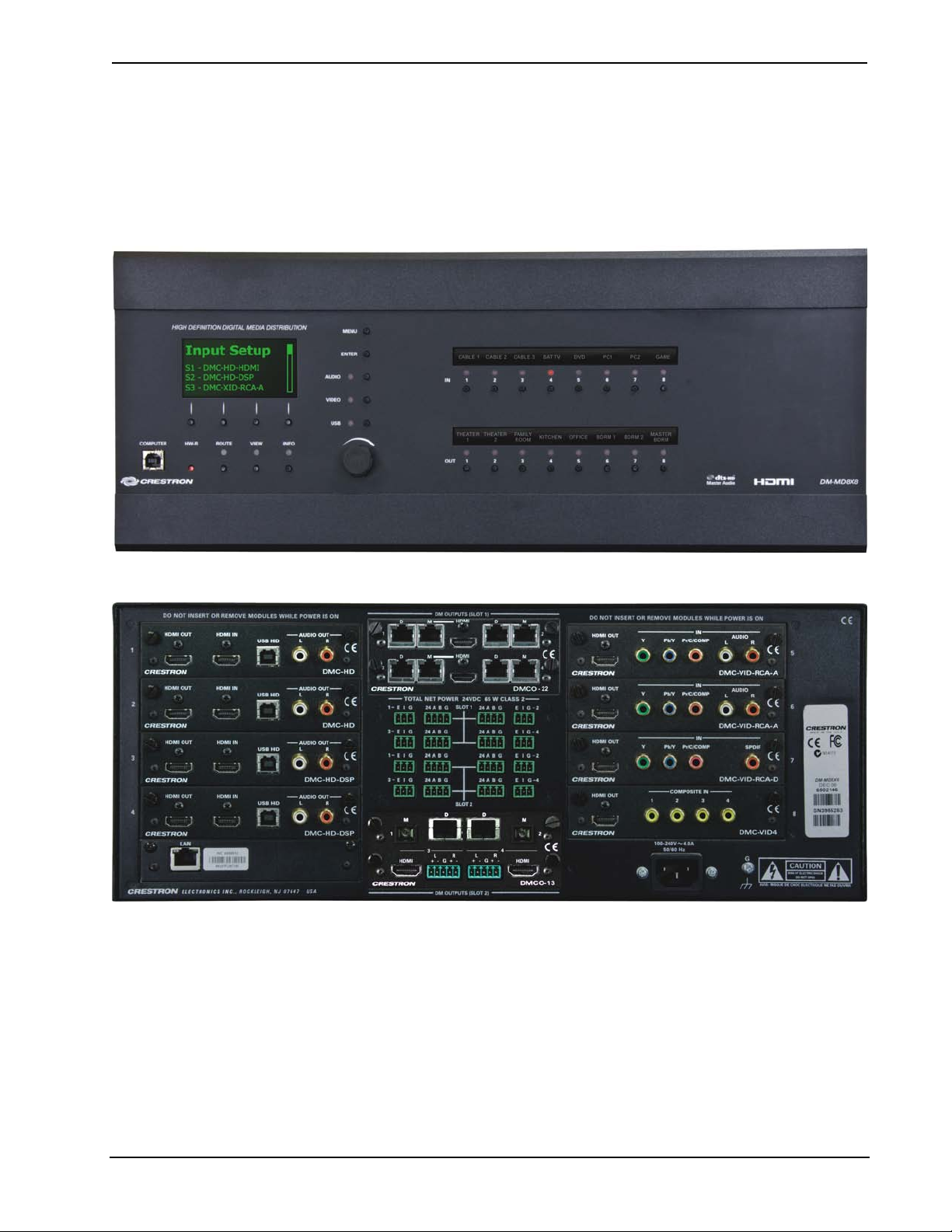
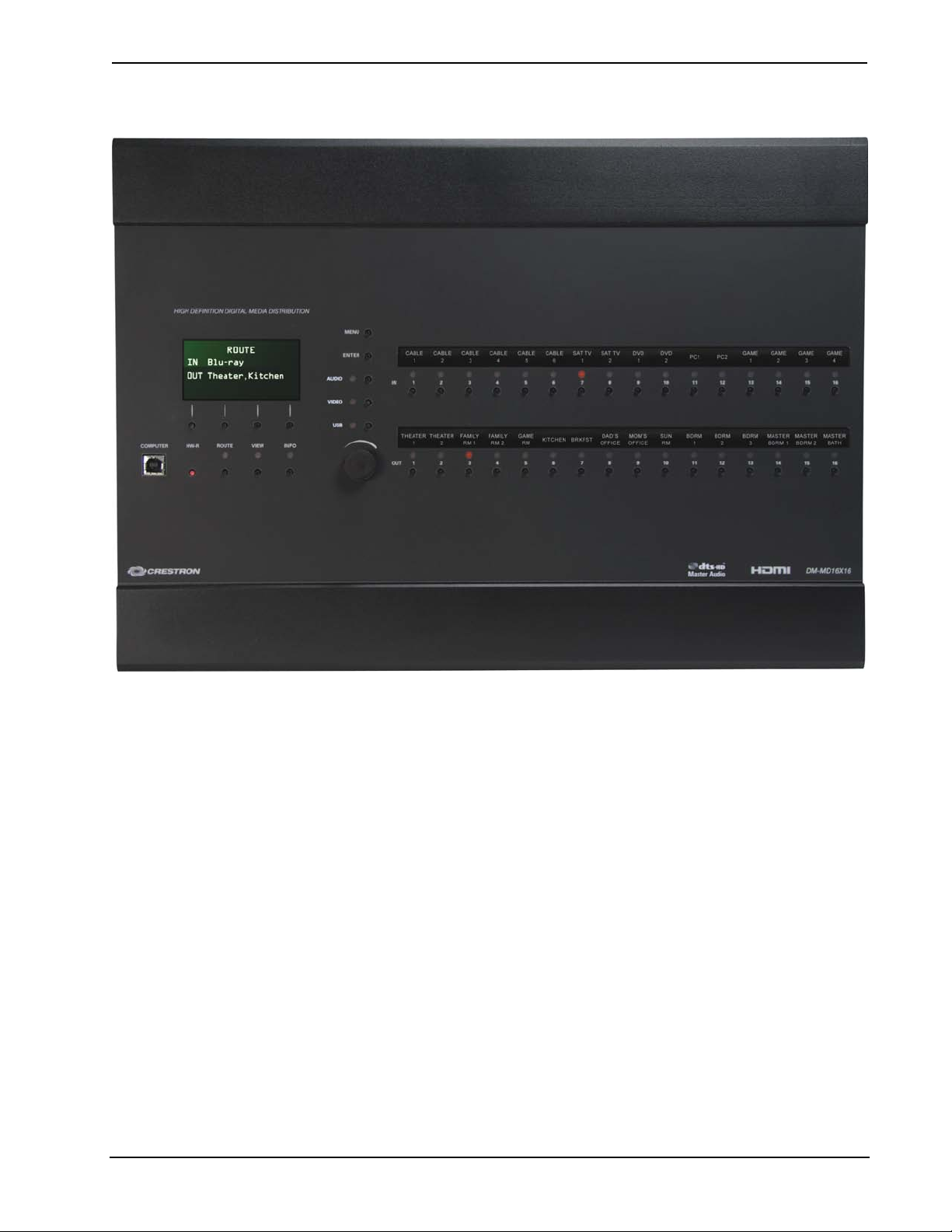
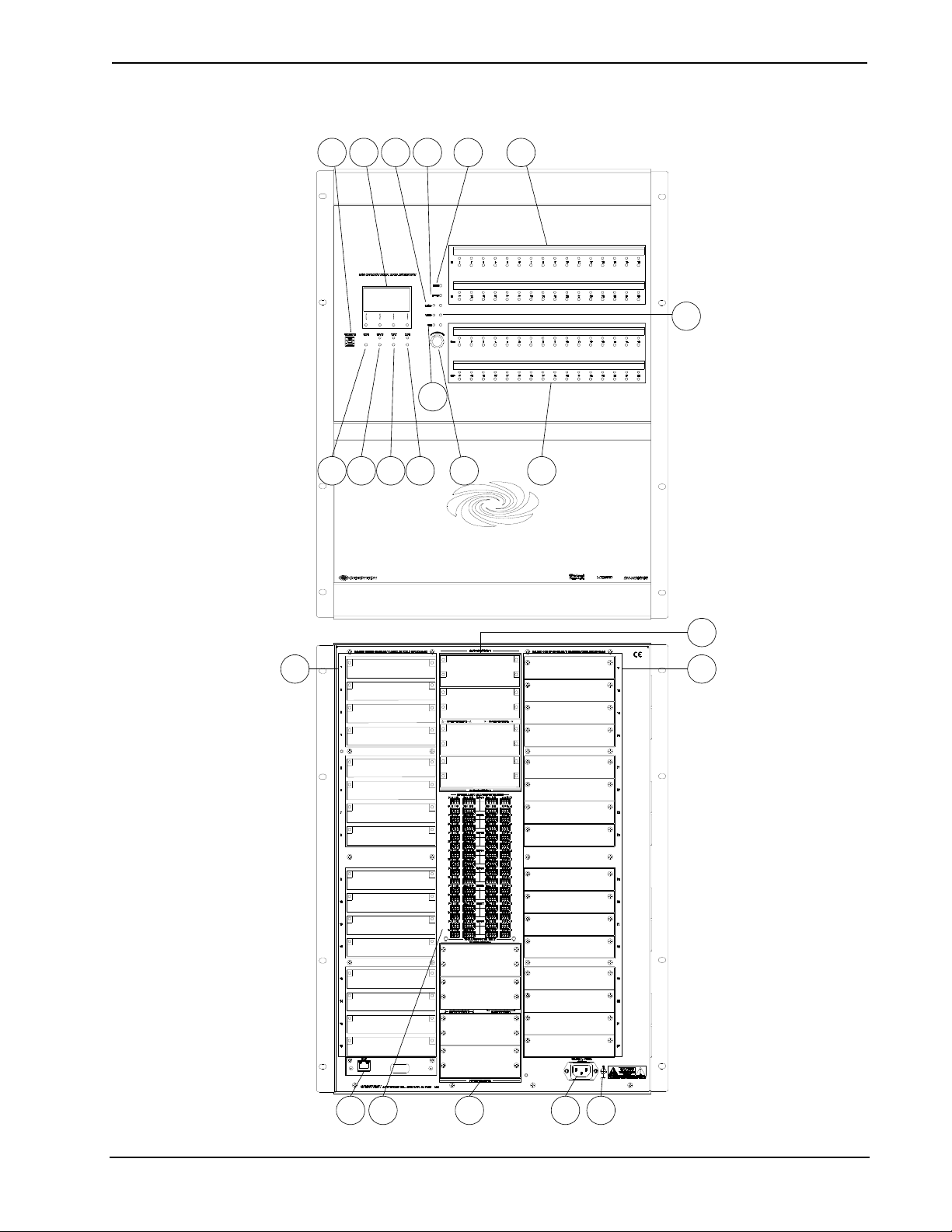
Physical Description
This section provides information on the connections, controls and indicators
available on the DM switchers.
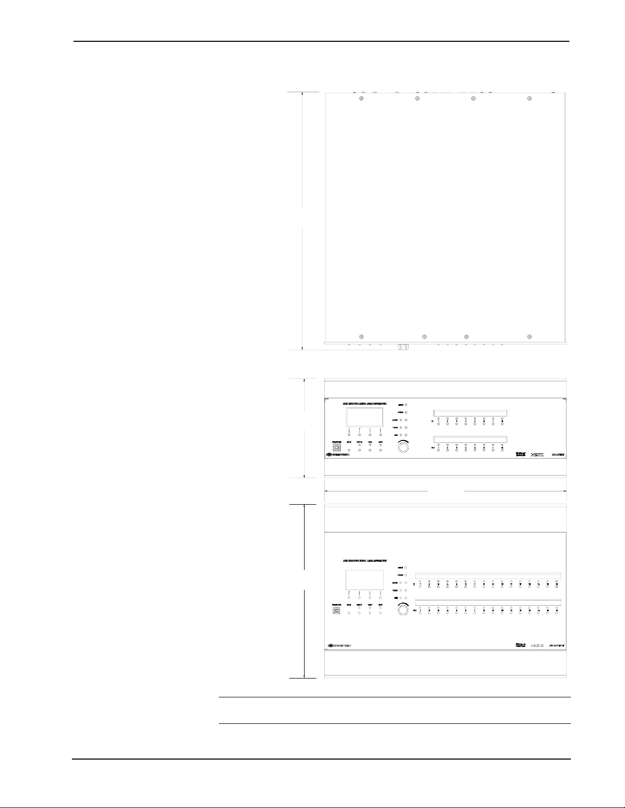
DM-MD8X8 Physical View (Front)
DM-MD8X8 Physical View (Rear, Shown with Optional DM Cards)
Operations Guide – DOC. 6755C DigitalMedia™ Switchers: DM-MD8X8/16X16/32X32 • 15
Page 22
DigitalMedia™ Switchers Crestron DM-MD8X8/16X16/32X32
DM-MD16X16 Physical View (Front)
16 • DigitalMedia™ Switchers: DM-MD8X8/16X16/32X32 Operations Guide – DOC. 6755C
Page 23
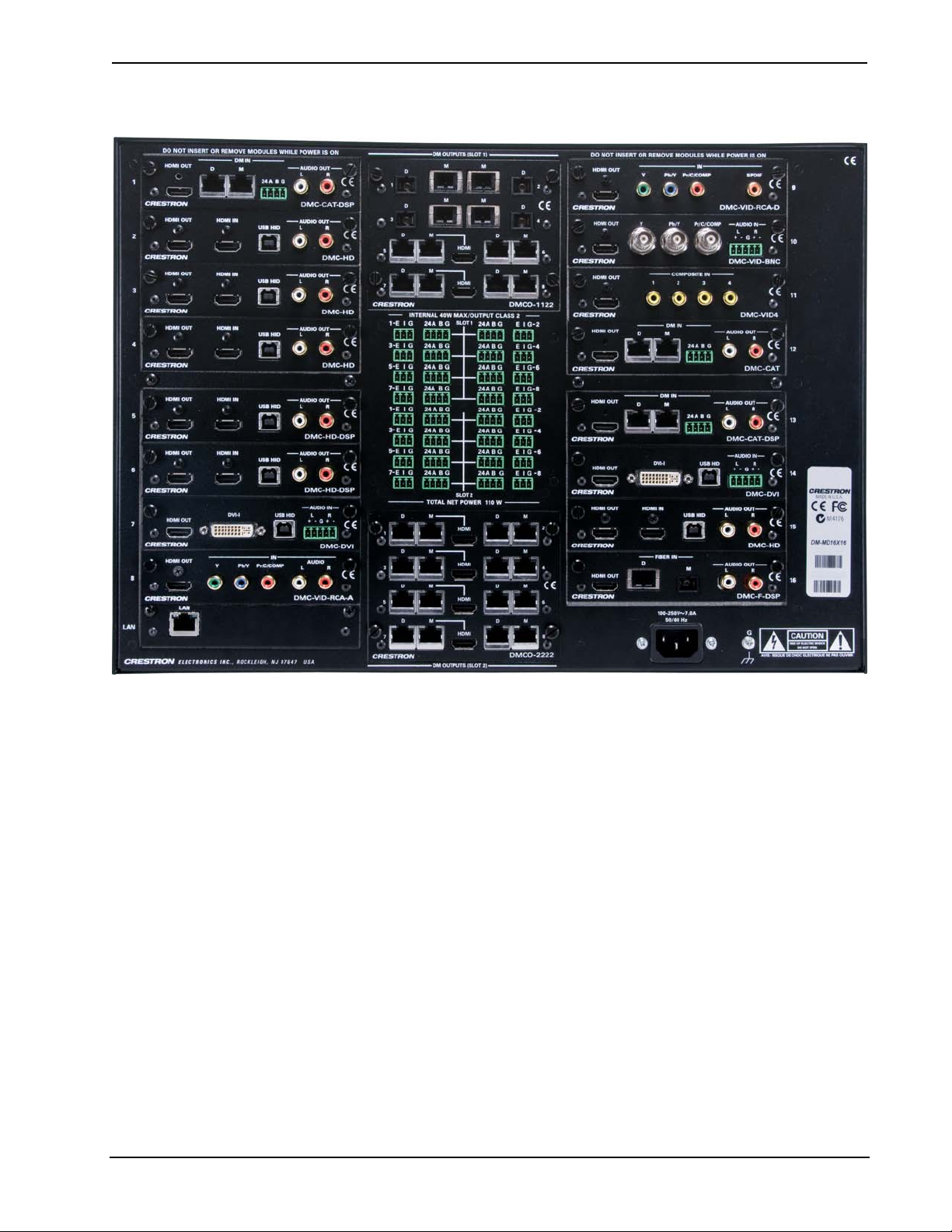
Crestron DM-MD8X8/16X16/32X32 DigitalMedia™ Switchers
DM-MD16X16 Physical View (Rear, Shown with Optional DM Cards)
Operations Guide – DOC. 6755C DigitalMedia™ Switchers: DM-MD8X8/16X16/32X32 • 17
Page 24
DigitalMedia™ Switchers Crestron DM-MD8X8/16X16/32X32
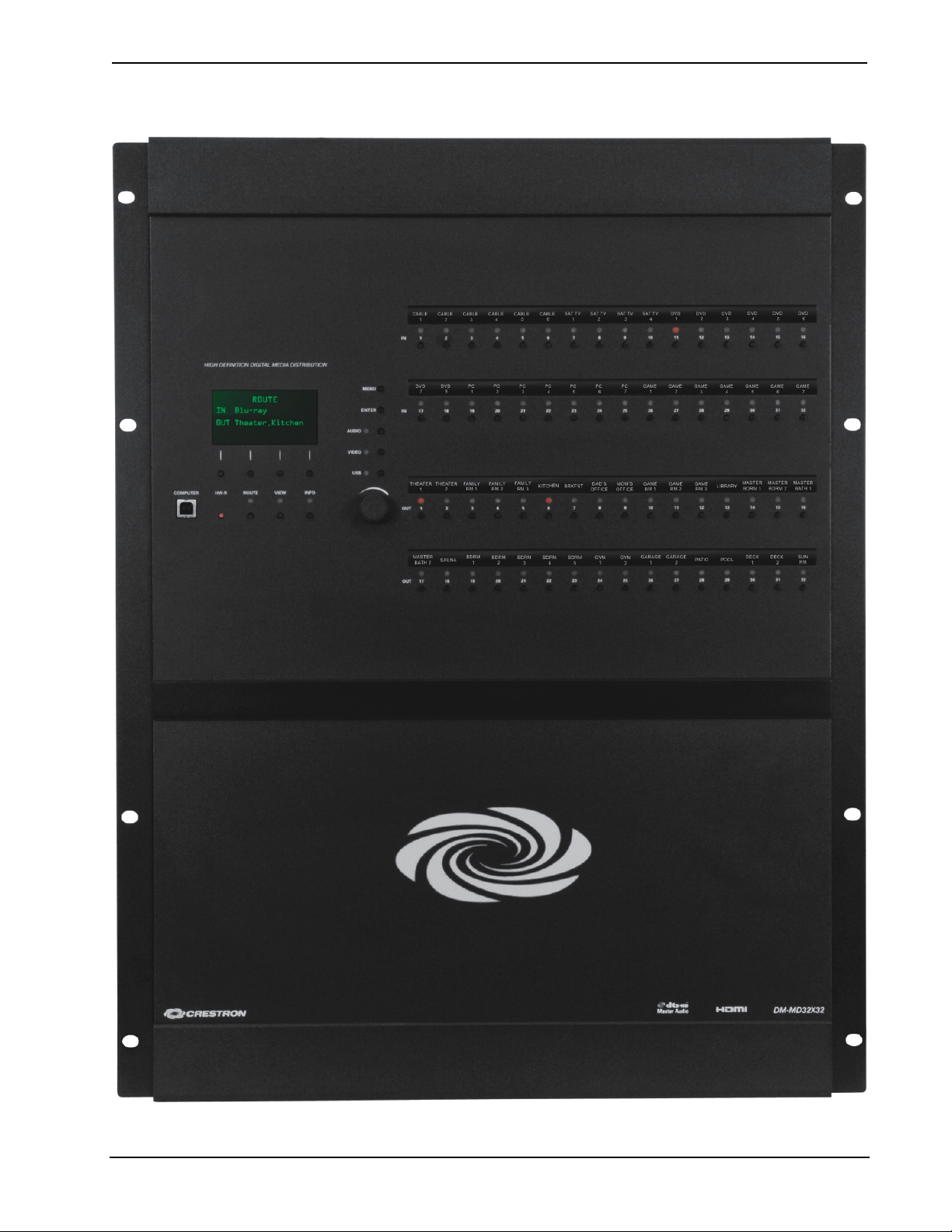
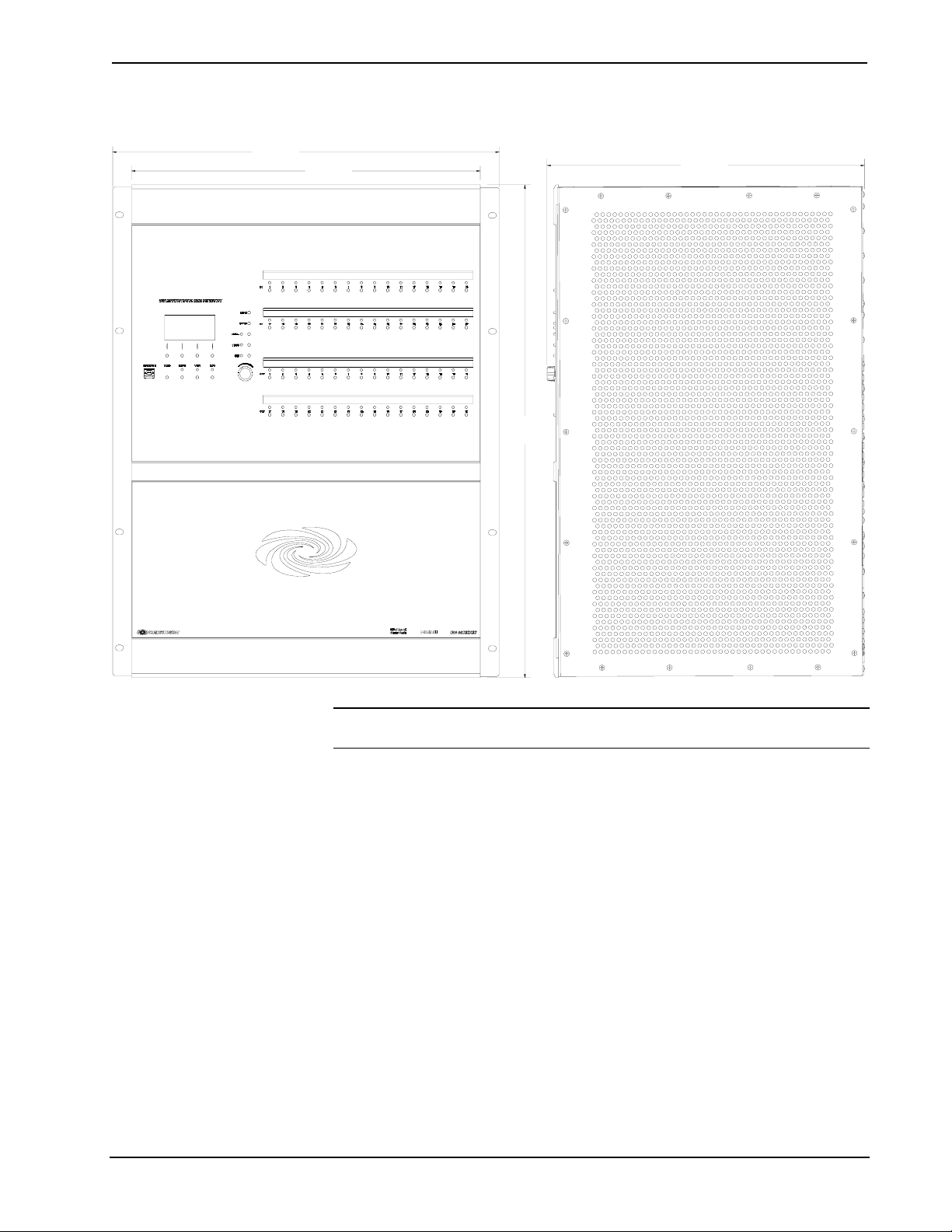
DM-MD32X32 Physical View (Front)
18 • DigitalMedia™ Switchers: DM-MD8X8/16X16/32X32 Operations Guide – DOC. 6755C
Page 25
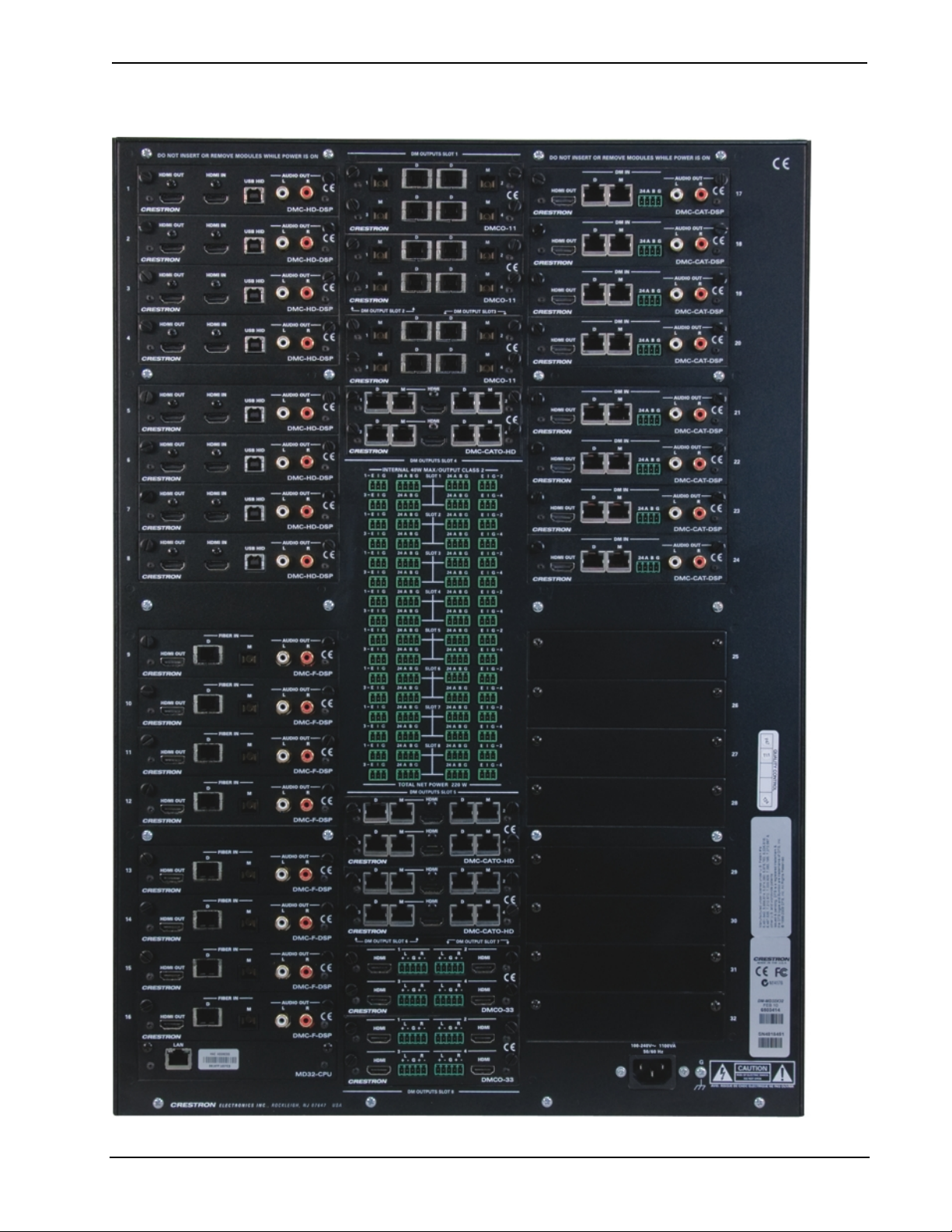
Crestron DM-MD8X8/16X16/32X32 DigitalMedia™ Switchers
DM- MD32X32 Physical View (Rear, Shown with Optional DM Cards)
Operations Guide – DOC. 6755C DigitalMedia™ Switchers: DM-MD8X8/16X16/32X32 • 19
Page 26
DigitalMedia™ Switchers Crestron DM-MD8X8/16X16/32X32
DM-MD8X8 & DM-MD16X16 Overall Dimensions
18.13 in
(461 mm)
DM-MD8X8
DM-MD16X16
6.97 in
(177 mm)
17.28 in
(439 mm)
12.22 in
(311 mm)
NOTE: Cable connections can extend the overall depth of the DM switcher by
approximately two to three inches.
20 • DigitalMedia™ Switchers: DM-MD8X8/16X16/32X32 Operations Guide – DOC. 6755C
Page 27
Crestron DM-MD8X8/16X16/32X32 DigitalMedia™ Switchers
DM-MD32X32 Overall Dimensions
19.15 in
(487 mm)
17.28 in
(439 mm)
24.44 in
(621 mm)
15.72 in
(400 mm)
NOTE: Cable connections can extend the overall depth of the DM switcher by
approximately two to three inches.
Operations Guide – DOC. 6755C DigitalMedia™ Switchers: DM-MD8X8/16X16/32X32 • 21
Page 28
DigitalMedia™ Switchers Crestron DM-MD8X8/16X16/32X32
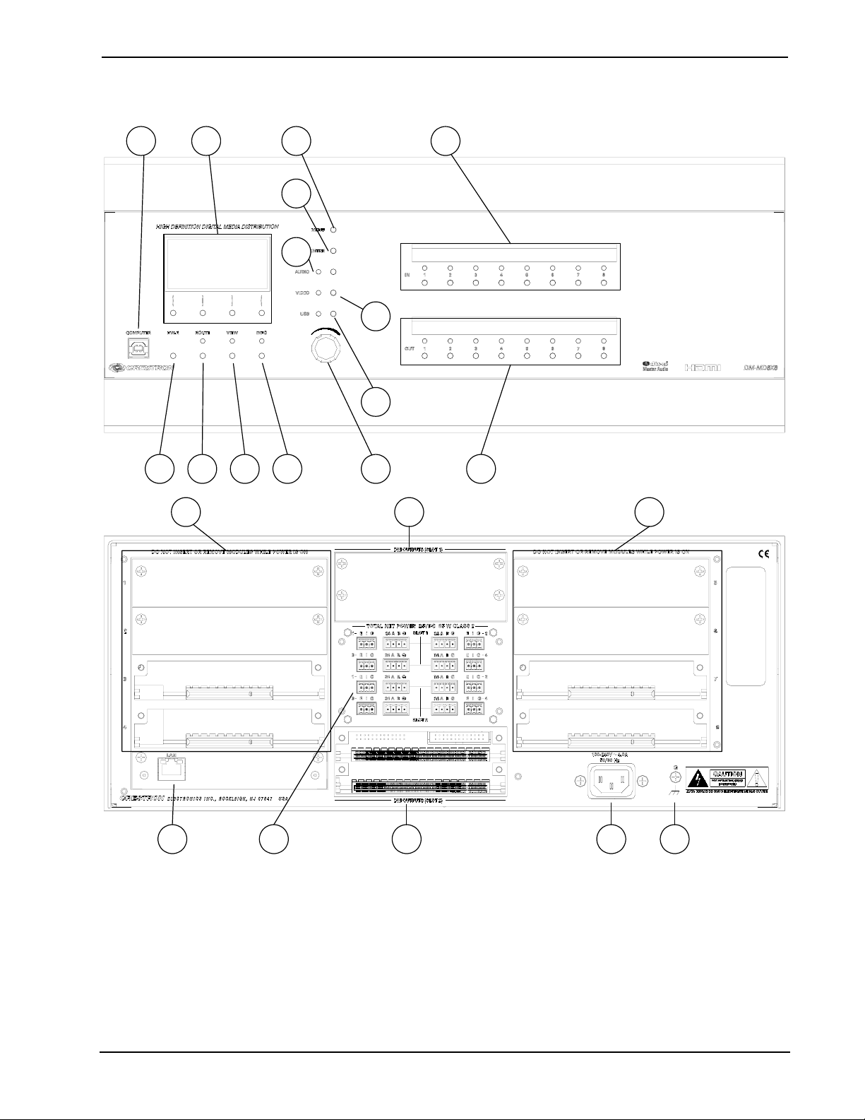
DM-MD8X8 Buttons and Ports
1 2
3 4 5 6
15 17
7
8
9
10
11
12
13
14
15
16 18 17
22 • DigitalMedia™ Switchers: DM-MD8X8/16X16/32X32 Operations Guide – DOC. 6755C
19 20
Page 29
Crestron DM-MD8X8/16X16/32X32 DigitalMedia™ Switchers
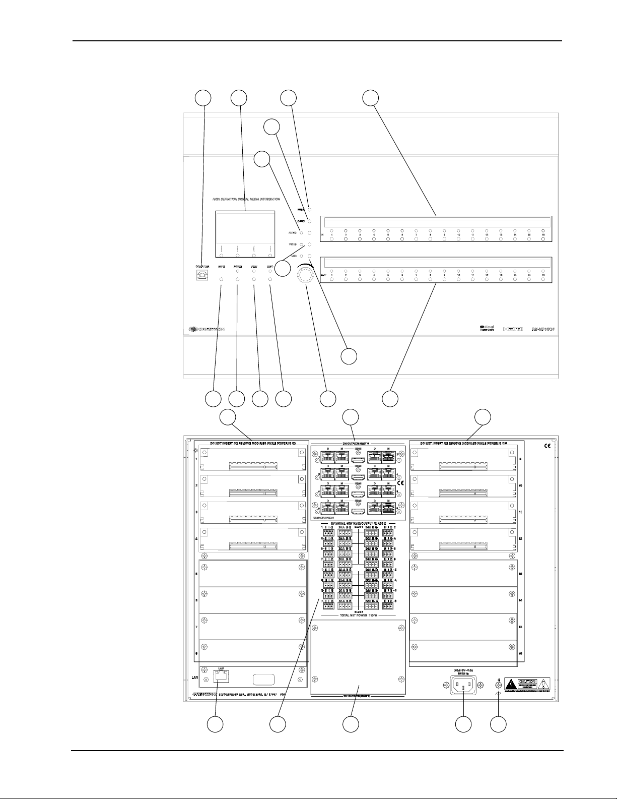
DM-MD16X16 Buttons and Ports
1 2
7
8
9
10
13
11
3 4 5 6
15 17 15
12
14
18 17 19 2016
Operations Guide – DOC. 6755C DigitalMedia™ Switchers: DM-MD8X8/16X16/32X32 • 23
Page 30
DigitalMedia™ Switchers Crestron DM-MD8X8/16X16/32X32
DM-MD32X32 Buttons and Ports
1 2
3 4 5 6
9 8 7
11
12
13
10
14
15
17
15
18 17 19 2016
24 • DigitalMedia™ Switchers: DM-MD8X8/16X16/32X32 Operations Guide – DOC. 6755C
Page 31

Crestron DM-MD8X8/16X16/32X32 DigitalMedia™ Switchers
Connectors, Controls & Indicators
#
CONNECTORS
CONTROLS &
INDICATORS
1
,
DESCRIPTION
1 COMPUTER
Pin 2 Pin 1
Pin 3 Pin 4
2
3 HW-R BUTTON
4
5 VIEW BUTTON & LED
6 INFO BUTTON & LED
7 MENU BUTTON (1) pushbutton, steps menu back one level
8 ENTER BUTTON
9
10
11 USB BUTTON & LED
12
LIQUID CRYSTAL
DISPLAY & SOFT
BUTTONS
ROUTE BUTTON &
LED
AUDIO BUTTON &
LED
VIDEO BUTTON &
LED
SELECTION KNOB
USB Type B female; USB 1.1 computer
console port (6 ft cable included)
PIN DESCRIPTION
1 +5 VDC
2 Data 3 Data +
4 Ground
LIQUID CRYSTAL DISPLAY (LCD):
Green LCD dot matrix, 128 x 64 resolution,
adjustable LED backlight;
Displays inputs/outputs by name, video &
audio signal information, Ethernet
configuration and setup menus;
SOFT BUTTONS:
(4) pushbuttons for activation of LCD driven
functions
(1) recessed miniature pushbutton for
hardware reset, reboots the switcher
(1) pushbutton and red LED, selects Route
mode to allow routing changes
(1) pushbutton and red LED, selects View
mode for viewing current routes
(1) pushbutton and red LED, selects Info
mode for viewing AV and device information
(1) pushbutton, executes highlighted menu or
value
(1) pushbutton & red LED, selects audio
routing view
(1) pushbutton & red LED, selects video
routing view
(1) pushbutton & red LED, selects USB
routing view
(1) Continuous turn rotary encoder, adjusts
menu parameters
13
(Continued on following page)
Operations Guide – DOC. 6755C DigitalMedia™ Switchers: DM-MD8X8/16X16/32X32 • 25
IN 1-8/16/32
DM-MD8X8
(8) pushbuttons and red LEDs, select input for
routing
DM-MD16X16
(16) pushbuttons and red LEDs, select input
for routing
DM-MD32X32
(32) pushbuttons and red LEDs, select input
for routing
Page 32

DigitalMedia™ Switchers Crestron DM-MD8X8/16X16/32X32
Connectors, Controls & Indicators (Continued)
#
14
15
16
17
CONNECTORS
CONTROLS &
INDICATORS
OUT 1-8/16/32
CARD SLOTS
1-8/16/32
LAN
DM OUTPUT SLOT2
1 & 2 / 1-8
1
,
DM-MD8X8
(8) pushbuttons and red LEDs, select output
for routing
DM-MD16X16
(16) pushbuttons and red LEDs, select output
for routing
DM-MD32X32
(32) pushbuttons and red LEDs, select output
for routing
DM-MD8X8
(8) DM switcher input card slots; Accepts (1)
DMC-series input card; Input cards are fieldinstallable
DM-MD16X16
(16) DM switcher input card slots; Accepts (1)
DMC-series input card; Input cards are fieldinstallable
DM-MD32X32
(32) DM switcher input card slots; Accepts (1)
DMC-series input card; Input cards are fieldinstallable
(1) 8-wire RJ-45 with 2 LED indicators,
10/100/1000BASE-T Ethernet port; Green
LED indicates link status, Yellow LED
indicates Ethernet activity
DM-MD8X8 and DM-MD16X16
(2) DM switcher output card slots; Each slot
accepts (1) 4-channel (DM-MD8X8) or
(1) 8-channel (DM-MD16X16) DM output
card;
DM-MD32X32
(8) DM switcher output card slots; Each slot
accepts (1) 4-channel DM output card;
DESCRIPTION
(Continued on following page)
26 • DigitalMedia™ Switchers: DM-MD8X8/16X16/32X32 Operations Guide – DOC. 6755C
Page 33

Crestron DM-MD8X8/16X16/32X32 DigitalMedia™ Switchers
Connectors, Controls & Indicators (Continued)
#
18
19
20
CONNECTORS
CONTROLS &
INDICATORS
24ABG/EIG 1 – 4
(SLOT 1 – 8)
100–240V ~ 4.0A/7.0A
50/60 Hz
GROUND
1
,
DM-MD8X8
(8) sets of (1) 4-pin and (1) 3-pin 3.5 mm
detachable terminal blocks
DM-MD16X16
(16) sets of (1) 4-pin and (1) 3-pin 3.5 mm
detachable terminal blocks
DM-MD32X32
(32) sets of (1) 4-pin and (1) 3-pin 3.5 mm
detachable terminal blocks
The following applies to all DM switchers:
Comprises (8, 16, or 32) DMNet ports with
“EIG” power selection ports, each set
associated with a corresponding DM output
port on the output card in either output slot;
Each DMNet port provides power and
communications for a DM device connected
via DM cable;
Each EIG port connects to an external power
supply3, or to the internal power source via a
jumper, to power the DM device connected to
the corresponding DMNet port;
Maximum Load: 75 Watts (3.13 Amps @ 24
Volts DC) per port, when connected to
external power supply3, otherwise limited to
available DMNet power
(1) IEC Socket, main power input; Mates with
removable power cord (included)
DM-MD8X8: 4.0 Amps Max. Current Draw
DM-MD16X16: 7.0 Amps Max. Current Draw
DM-MD32X32: 11 Amps Max. Current Draw
(1) 6-32 screw, chassis ground lug
DESCRIPTION
1. Interface connectors for DMNET and EIG ports are provided with the unit.
2. Output cards on DM-MD8X8 and DM-MD32X32 are field-installable (DMC-series). Output cards on
DM-MD16X16 (DMCO-series) require factory installation.
3. For external DMNet power, use Crestron CNPWS-75, C2N-SPWS300, or other Cresnet power supply
as required.
Operations Guide – DOC. 6755C DigitalMedia™ Switchers: DM-MD8X8/16X16/32X32 • 27
Page 34

DigitalMedia™ Switchers Crestron DM-MD8X8/16X16/32X32
Setup
DigitalMedia Wiring
Connections between DigitalMedia Switchers and DigitalMedia Room Controllers
can be made using a variety of wiring solutions. For optimum performance, Crestron
recommends Crestron DigitalMedia cable or CresFiber.
When wiring the DigitalMedia network, consider the following:
• Use Crestron Certified Wire.
• Use Crestron power supplies for Crestron equipment.
• Provide sufficient power to the system.
CAUTION: Insufficient power can lead to unpredictabl e resul t s or damage
to the equipment. Please use the Crestron Power Calculator to help calculate
how much power is needed for the system (
www.crestron.com/calculators).
For information on connecting Ethernet devices in a Crestron system, refer to the
latest version of the Crestron e-Control
available for download from the Crestron website (
®
Reference Guide (Doc. 6052), which is
www.crestron.com/manuals).
DigitalMedia Cable
The Crestron DigitalMedia cable contains two CAT5E cables (one shielded, one
unshielded) and one DMNet cable in triamese jackets. Installation of any
DigitalMedia device is as simple as connecting DigitalMedia cable from the output
of the DigitalMedia switcher to the input of a DigitalMedia device such as a
DM-RMC-100 DigitalMedia Room Controller. For more information, refer to the
latest version of the Crestron DigitalMedia Design Guide (Doc. 4789), which is
available for download from the Crestron website (
The following pinouts are given for DigitalMedia cable:
D and M Port Wiring
8
1
PIN WIRE COLOR
1 Orange/White
2 Orange
3 Green/White
4 Blue
5 Blue/White
6 Green
7 Brown/White
8 Brown
www.crestron.com/digitalmedia).
28 • DigitalMedia™ Switchers: DM-MD8X8/16X16/32X32 Operations Guide – DOC. 6755C
Page 35

Crestron DM-MD8X8/16X16/32X32 DigitalMedia™ Switchers
24 A B G Port Wiring
PIN SIGNAL DESC. WIRE COLOR
24 +24V DC Power Red
A DM-Net+ DMNet Orange
B DM-Net- DMNet Grey
G GND DC Ground Black
NOTE: Do not untwist the two wires in a single pair for more than 1/3-1/2”
(8-12 mm) when making a connection. The twists are critical to canceling out
interference between the wires.
The maximum transmission distances between repeaters are determined by the video
resolution sent over the wires. The total distance that video can be sent using
repeaters is shown in the following table for DigitalMedia cable. While up to three
repeaters may be used to extend the transmission distance, the aggregate length of a
cable run must not exceed 450 feet (137.1 meters) when using DigitalMedia cable.
The following table shows the maximum cable lengths allowed between repeaters
when using DigitalMedia cable.
Maximum Resolution and Cable Length
Cable Type: DM-CBL DigitalMedia Cable
Maximum length
without, between,
before or after
Resolution:
repeaters
720p, 1080i, 1080p24 200 ft (60 m)
Maximum total
length using up
to 2 repeaters
450 ft (137 m)
1024x768 @ 75 Hz 200 ft (60 m) 450 ft (137 m)
1080p60 150 ft (45 m) 450 ft (137 m)
1280x1024 @ 75 Hz 150 ft (45 m) 450 ft (137 m)
1920x1200 @ 60 Hz 150 ft (45 m) 450 ft (137 m)
1600x1200 @ 60 Hz 125 ft (38 m) 375 ft (114 m)
1080p60 Deep Color 100 ft (30 m) 300 ft (91 m)
NOTE: 1080p60 is the most common resolution used in residential installations.
NOTE: Deep color is part of the HDMI specification. It allows devices to transmit
video using 36 bits per pixel instead of 24 bits per pixel. The color depth allows for
4096 shades each of red, green, and blue (inst ead of 2 56 ). Due to bandwidth
requirements and limited support, deep color is not often used.
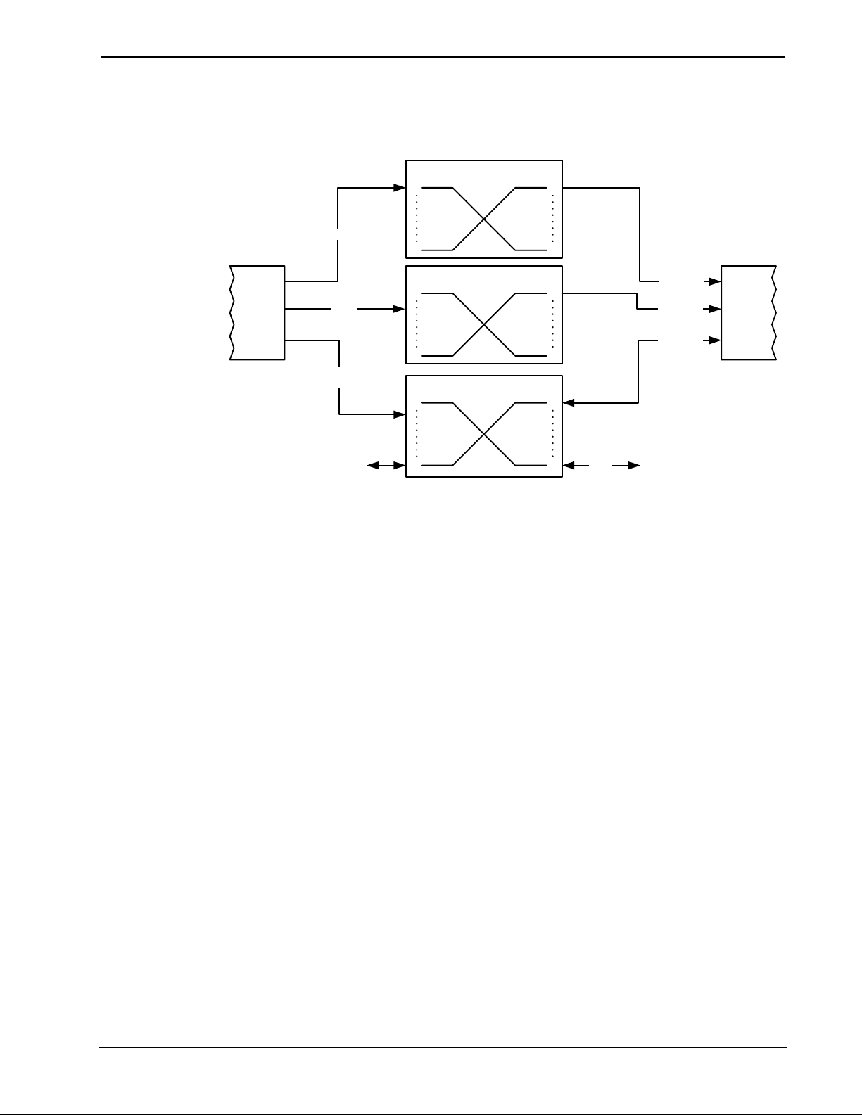
Up to two repeaters can be used to extend the transmission distance between the DM
switcher and the Room Controller. The following diagram illustrates the maximum
hop length between switcher/room controller and repeaters and maximum aggregate
cable length.
Operations Guide – DOC. 6755C DigitalMedia™ Switchers: DM-MD8X8/16X16/32X32 • 29
Page 36

DigitalMedia™ Switchers Crestron DM-MD8X8/16X16/32X32
Maximum Cable Lengths
DM
SWITCHER
H = The maximum hop distance between a DM Switcher/ DM-RMC-100 Room Controller and a DM-DR Repeater
T = The maximum total distance from the DM Switcher to the DM-RMC-100 Room Controller
DM DM DM
H H H
DM-DR
REPEATER
DM-DR
REPEATER
T
DM-RMC-100
ROOM
CONTROLLER
For more information on DigitalMedia and other cable products, visit the Crestron
website (http://www.crestron.com/wireoverview).
CresFiber
CresFiber provides for longer distances between the DigitalMedia switcher and a
DigitalMedia Room Controller without the use of repeaters or sacrifice in video
resolution. For more information, refer to the latest revision of the Crestron
DigitalMedia Design Guide (Doc. 4789), which is available for download from the
Crestron website.
The following table lists the maximum cable length of CresFiber.
Maximum Length Using CresFiber
RESOLUTION CRESFIBER
720p, 1080i, 1080p24
1024 x 768 @ 75 Hz
1280 x 1024 @ 75 Hz
1600 x 1200 @ 60 Hz
1000’
(~300 m)
1920 x 1200 @ 60 Hz
1080p60
1080p60 Deep Color
Other fiber optic cable can be used as well.
NOTE: 1080p60 is the most common resolution used in residential installations.
NOTE: Deep color is part of the HDMI specification. It allows devices to transmit
video using 36 bits per pixel instead of 24 bits per pixel. The color depth allows for
4096 shades each of red, green, and blue (inst ead of 2 56 ). Due to bandwidth
requirements and limited support, deep color is not often used.
For more information on CresFiber and other cable products, visit the Crestron
website (http://www.crestron.com/wireoverview).
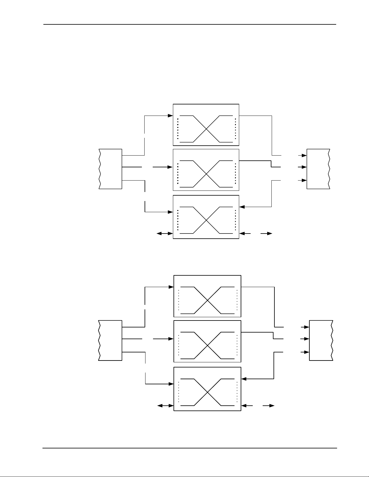
HDCP Signal Path
Sources using HDCP limit the number of display devices it can transmit to while
simultaneously limiting the depth of devices in the signal path. Too many devices or
30 • DigitalMedia™ Switchers: DM-MD8X8/16X16/32X32 Operations Guide – DOC. 6755C
Page 37

Crestron DM-MD8X8/16X16/32X32 DigitalMedia™ Switchers
greater-than-allowed depth in a signal path (from source to display) may create
problems with displaying of audio and video content. The HDCP specification states
that the maximum depth of devices between source and display is six. Some
examples are shown in the following diagram.
Examples of Reported HDCP Devices and Reported HDCP Depth
Operations Guide – DOC. 6755C DigitalMedia™ Switchers: DM-MD8X8/16X16/32X32 • 31
Page 38

DigitalMedia™ Switchers Crestron DM-MD8X8/16X16/32X32
Ethernet Setup
DigitalMedia switchers are designed to control the Ethernet settings of lightweight
DM devices around them in order to reduce the amount of IP configuration necessary
and make the certain DM devices swappable without reconfiguration.
IP Configuration
DigitalMedia switchers have the ability to operate in DHCP or Static IP address
mode. In addition, DM switchers control the IP addressing information for input
cards that have Ethernet capabilities as well as neighboring DigitalMedia devices.
When the DM switcher is set to DHCP mode, these cards and DM devices will also
be set to DHCP mode. When the DM switcher is set into Static IP mode, these cards
and DM devices will receive a Static IP configuration equivalent to the DM
switcher’s IP address plus their slot number. This configuration is sent when the DM
switcher starts up.
Example:
A DM-MD8X8 is set to IP address 192.168.1.30. The IP mask is 255.255.255.0 and
the default router is 192.168.1.1. The HDMI input card on slot 3 would be set to IP
address 192.168.1.33 and receive the same IP mask and default router as the DM
switcher.
Since there can be up to 64 slots in the DigitalMedia switcher, the last octet in the
DM switcher IP address may not be set higher than 222 (DM-MD8x8 and
DM-MD16X16) or 190 (DM-MD32X32). Otherwise not all devices will receive a
valid IP address.
DigitalMedia devices that send this IP configuration are the DM-MD8X8,
DM-MD16X16, and the DM-MD32X32.
DigitalMedia devices that receive this IP configuration are the DMC-HD,
DMC-HD-DSP, DMC-DVI, DM-RMC-100, DM -RM C -1 0 0-F, DM-TX-100, and
DM-TX-200.
If two DigitalMedia switchers were connected to one another via a DMC-CATO
output and DMC-CAT input card, each switcher would maintain control over its own
IP configuration.
IP Table Setup
DigitalMedia devices that receive their IP address configuration via the switcher can
also receive their IP table configuration from the DM switcher.
For more information, refer to “IP Table Options” on page 63.
Identity Code
32 • DigitalMedia™ Switchers: DM-MD8X8/16X16/32X32 Operations Guide – DOC. 6755C
The IP ID can be set from the front panel using Installer Tools or in the
DM switcher’s IP table using Crestron Toolbox™. For information on using Installer
Tools to set the IP ID, refer to “Control System IP ID” on page 48. For information
on setting an IP table, refer to the Crestron Toolbox help file. The IP IDs of multiple
DM switchers in the same system must be unique.
When setting the IP ID, consider the following:
• The IP ID of each unit must match an IP ID specified in the SIMPL™
Windows program.
• Each device using IP to communicate with a control system must have a
unique IP ID.
Page 39

Crestron DM-MD8X8/16X16/32X32 DigitalMedia™ Switchers
Installation
Ventilation
Rack Mounting
The DM switcher should be used in a well-ventilated area. The venting holes should
not be obstructed under any circumstances.
To prevent overheating, do not operate this product in an area that exceeds the
environmental temperature range listed in the table of specifications. Consider using
forced air ventilation and/or increasing the spacing between units to reduce
overheating. Consideration must be given if installed in a closed or multi-unit rack
assembly since the operating ambient temperature of the environment may be greater
than the room ambient temperature. Contact with thermal insulating materials should
be avoided on all sides of the unit.
A DM switcher can be mounted in a rack or stacked with other equipment. Two
“ears” are provided with the switcher so that the unit can be rack mounted. These
ears must be installed prior to mounting. Complete the following procedure to attach
the ears to the unit. The only tool required is a #2 Phillips screwdriver.
WARNING: To prevent bodily injury when mounting or servicing this unit in a
rack, take special precautions to ensure that the system remains stable. The following
guidelines are provided to ensure your safety:
• When mounting this unit in a partially filled rack, load the rack from the
bottom to the top with the heaviest component at the bottom of the rack.
• If the rack is provided with stabilizing devices, install the stabilizers before
mounting or servicing the unit in the rack.
NOTE: The DM-MD32X32 has rack ears molded into the chassis. They cannot be
removed.
NOTE: If rack mounting is not required, rubber feet are provided for tabletop
mounting or stacking. Apply the feet near the corner edges on the underside of the
unit.
NOTE: Reliable earthing of rack-mounted equipment should be maintained.
Particular attention should be given to supply connections other than direct
connections to the branch circuit (e.g. use of power strips).
To install the ears:
1. There are screws that secure each side of the DM switcher’s top cover.
Using a #2 Phillips screwdriver, remove three screws from one side of the
unit as shown in the diagram of step 3.
2. Position a rack ear so that its mounting holes align with the holes vacated
by the screws in step 1.
3. Secure the ear to the unit with three screws from step 1, as shown in the
following diagram.
Operations Guide – DOC. 6755C DigitalMedia™ Switchers: DM-MD8X8/16X16/32X32 • 33
Page 40

DigitalMedia™ Switchers Crestron DM-MD8X8/16X16/32X32
Ear Attachment for Rack Mounting (DM-MD8X8 shown)
USE COVER SCREWS
4. Repeat procedure (steps 1 through 3) to attach the remaining ear to the
opposite side.
Stacking
Connect the Device
Four “feet” are provided with the DM-MD8X8, DM-MD16X16 and the
DM-MD32X32 so that if the units are not rack mounted, the rubber feet can provide
stability when the units are placed on a flat surface or stacked. These feet should be
attached near the corners prior to the hookup procedure.
NOTE: No more than two DM switchers should be stacked.
Hardware Hookup
Make the necessary connections as called out in the illustration that follows this
paragraph. For details on making connections to installed DM input cards and DM
output cards, refer to “Appendix A: Hardware Hookup for DM Cards” on page 75.
Apply power after all connections have been made.
When making connections to the DM switcher, use Crestron power supplies for
Crestron equipment.
34 • DigitalMedia™ Switchers: DM-MD8X8/16X16/32X32 Operations Guide – DOC. 6755C
Page 41

Crestron DM-MD8X8/16X16/32X32 DigitalMedia™ Switchers
Hardware Connections for the DM-MD8X8, Front
COMPUTER:
To USB Port On PC
Hardware Connections for the DM-MD16X16, Front
COMPUTER:
To USB Port On
PC
Operations Guide – DOC. 6755C DigitalMedia™ Switchers: DM-MD8X8/16X16/32X32 • 35
Page 42

DigitalMedia™ Switchers Crestron DM-MD8X8/16X16/32X32
Hardware Connections for the DM-MD32X32, Front
COMPUTER:
To USB Port On
PC
36 • DigitalMedia™ Switchers: DM-MD8X8/16X16/32X32 Operations Guide – DOC. 6755C
Page 43

Crestron DM-MD8X8/16X16/32X32 DigitalMedia™ Switchers
Hardware Connections for the DM-MD8X8, Rear
DM INPUT CARD SLOTS 1-4:
Install Cards to Receive Input
Signals from Audio, Video, and PC
10/100/1000BASE-T
Sources
LAN:
Ethernet to LAN
DMNET PORTS (SLOT 2):
Connect to DM Receivers and Select
DM OUTPUTS (SLOT 1):
Install Card to Transmit DigitalMedia
Signals to DigitalMedia Room Controllers
Internal or External Power
DMNET PORTS (SLOT 1):
Connect to DM Receivers and Select
Internal or External Power
DM OUTPUTS (SLOT 2):
Install Card to Transmit DigitalMedia
Signals to DigitalMedia Room Controllers
POWER:
From Line Voltage
DM INPUT CARD SLOTS 5-8:
Install Cards to Receive Input
Signals from Audio, Video, and PC
Sources
GROUND:
Tie All Source and
Device Grounds to
GROUND Terminal
Operations Guide – DOC. 6755C DigitalMedia™ Switchers: DM-MD8X8/16X16/32X32 • 37
Page 44

DigitalMedia™ Switchers Crestron DM-MD8X8/16X16/32X32
Hardware Connections for the DM-MD16X16 Rear
DM INPUT CARD SLOTS 1-8:
Install Cards to Receive Input
Signals from Audio, Video, and PC
Sources
DM OUTPUTS (SLOT 1):
Factory-Installed Card to Transmit
DigitalMedia Signals to DigitalMedia Room
Controllers
DMNET PORTS (SLOT 1):
Connect to DM Receivers and Select
Internal or External Power
DM INPUT CARD SLOTS 9-16:
Install Cards to Receive Input
Signals from Audio, Video, and PC
Sources
LAN:
10/100/1000BASE-T
Ethernet to LAN
DMNET PORTS (SLOT 2):
Connect to DM Receivers and Select
Internal or External Power
DM OUTPUTS (SLOT 2):
Factory-Installed Card to Transmit
DigitalMedia Signals to DigitalMedia
Room Controllers
POWER:
From Line Voltage
GROUND:
Tie All Source and
Device Grounds to
GROUND Terminal
38 • DigitalMedia™ Switchers: DM-MD8X8/16X16/32X32 Operations Guide – DOC. 6755C
Page 45

Crestron DM-MD8X8/16X16/32X32 DigitalMedia™ Switchers
Hardware Connections for the DM-MD32X32Rear
DM INPUT CARD SLOTS 1-16:
Install Cards to Receive Input
Signals from Audio, Video, and PC
Sources
DM OUTPUTS (SLOTS 1-4):
Install Cards to Transmit DigitalMedia
Signals to DigitalMedia Room Controllers
DMNET PORTS (SLOTS 1-4):
Connect to DM Receivers and Select
Internal or External Power
DM INPUT CARD SLOTS 17-32:
Install Cards to Receive Input
Signals from Audio, Video, and PC
Sources
LAN:
10/100/1000BASE-T
Ethernet to LAN
DMNET PORTS (SLOTS 5-8):
Connect to DM Receivers and Select
Internal or External Power
DM OUTPUTS (SLOTS 5-8):
Install Cards to Transmit DigitalMedia
Signals to DigitalMedia Room Controllers
POWER:
From Line Voltage
GROUND:
Tie All Source and
Device Grounds to
GROUND Terminal
Operations Guide – DOC. 6755C DigitalMedia™ Switchers: DM-MD8X8/16X16/32X32 • 39
Page 46

DigitalMedia™ Switchers Crestron DM-MD8X8/16X16/32X32
NOTE: The actual configuration of the output cards are specified during ordering.
For details on output connections, refer to “Output Connections” on page 87.
NOTE: Ensure the unit is properly grounded by connecting the chassis ground lug
to an earth ground (building steel).
NOTE: For optimum performance, Crestron strongly recommends using DM cable
or CresFiber, available from Crestron. Other high-quality fiber optic cable (such as
InfiniCor300) may also be used with varyin g per fo rmance.
NOTE: When using fiber, it is recommended that you have at least two spare fibers
for each location. DM fiber components use SC multimode connectors.
DMNet Power
Devices connected to each DMNet port can receive power from the DM switcher’s
internal power supply or from an external power supply such as the C2N-SPWS300.
The DMNet ports are preconfigured for operation using the DM switcher’s internal
power supply.
To power a DMNet port externally from a Cresnet 24 VDC power supply, connect
the power supply to the E (External) and G (Ground) pins on the EIG connector as
shown in the following diagram.
Providing DMNet Power Externally
24 G
Creston 24 VDC
Power Supply
To power a DMNet port using the DM switcher’s internal power supply, install a
jumper on the EIG connector from the E (External) pin to the I (Internal) pin as
shown in the following diagram.
Providing DMNet Power Internally
Label the Buttons
Use Crestron Engraver software to print custom labels for the DM switcher’s front
panel buttons and LEDS. Crestron re commends printing on 100-pound paper. Paper
with a weight less than 100 pounds will tend to crumple while sliding in, while paper
with a weight of more than 100 pounds may not fit.
40 • DigitalMedia™ Switchers: DM-MD8X8/16X16/32X32 Operations Guide – DOC. 6755C
Page 47

Crestron DM-MD8X8/16X16/32X32 DigitalMedia™ Switchers
Configuration
After making all hardware connections, the DM switcher must be configured for
operation. The DM switcher can be configured from the DM switcher’s front panel
using Installer Tools or from a PC using Crestron To ol b ox. Thi s document contains
instructions for using Installer Tools. For information on using Crestron Toolbox to
configure the DM switcher, refer to the Crestron Toolbox help file.
Open Installer Tools
To open Installer Tools:
1. Press the MENU button.
2. Enter the password. The default password is 1234.
a. Use the selection knob and the soft buttons labeled g and h to enter
the password.
Enter Password
Enter Password
0000
< >
NOTE: If the password contains digits greater than 0 and less than 9,
the IN buttons (1 through 8) can be used to enter the password.
b. Turn the selection knob until the correct digit is displayed.
c. Press the h button to move the cursor to the next digit and select the
next digit in the password with the volume control. Press the g button
to move to the previous digit.
d. Press the ENTER button once the password is displayed. If an
incorrect password is entered, the display will show “Invalid
Password”. Press the soft button labeled OK to exit Installer Tools.
The password can be changed or disabled. For information on changing or
disabling the password, refer to “Password” on page 5 0 fo r more
information.
Operations Guide – DOC. 6755C DigitalMedia™ Switchers: DM-MD8X8/16X16/32X32 • 41
Page 48

DigitalMedia™ Switchers Crestron DM-MD8X8/16X16/32X32
The Installer Tools menu is displayed.
Installer Tools
Ins taller Tools
Inputs
Outputs
Network
Installer Tools is separated into six sections:
¾ Inputs: Configure and view the settings of input cards installed on
the DM switcher.
¾ Outputs: Configure and view the settings of the output cards
installed on the DM switcher.
Exit Installer Tools
¾ Network: Configure and view the Ethernet settings of the
DM switcher.
¾ Control: Configures and views the settings of the DM switcher
front panel.
¾ Message Log: Displays messages contained in the DM switcher
message log.
¾ Commission System: Manages HDCP keys and optimizes EDID
settings for devices connected to the DM switcher.
NOTE: Changes made to any setting will only be saved upon exiting Installer
Tools. For instructions on exiting Installer Tools, refer below.
To exit Installer Tools, press the MENU button. Press the soft button labeled Yes to
save any changes and exit Installer Tools or press the soft button labeled No to return
to Installer Tools.
Inputs
The Inputs section of Installer Tools is used to configure and view information about
input cards installed on the DM switcher. Any changes made to the Inputs section
will be saved upon exiting Installer Tools. For more information on exiting Installer
Tools, refer to “Exit Installer Tools” above.
To open the Inputs section of Installer Tools:
1. Open Installer Tools as described on page 41.
2. Turn the selection knob to highlight Inputs and press the ENTER button. A
list of installed input cards will be displayed.
42 • DigitalMedia™ Switchers: DM-MD8X8/16X16/32X32 Operations Guide – DOC. 6755C
Page 49

Crestron DM-MD8X8/16X16/32X32 DigitalMedia™ Switchers
Input Setup
Input Setup
1. DMC-VID4 Security Cam
2. DMC -VID -RC A- D Ana log
3. DMC -HD -DSP Advanc ed
3. To configure an input, turn the selection knob to highlight an inpu t and
press the ENTER button.
For instructions on configuring a specific input card model, refer to
“Appendix B: Input Card Configuration” on page 90.
4. To exit the Inputs section and return to Installer Tools, press the MENU
button.
Outputs
The Outputs section of Installer Tools is used to view information about output cards
installed on the DM switcher. Any changes made to the Outputs section will be
saved upon exiting Installer Tools. For more information on exiting Installer Tools,
refer to “Exit Installer Tools” on page 42.
To open the Outputs section of Installer Tools:
1. Open Installer Tools as described on page 41.
2. Turn the selection knob to highlight Outputs and press the ENTER butt o n.
A list of outputs will be displayed.
Output Setup
Output Setup
1. DMC-CATO-HD – CAT5
2. DMC-CATO-HD – CAT5
3. DMC-CATO-HD – CAT5
3. To configure an output, turn the selection knob to highlight an output and
press the ENTER button.
For instructions on configuring a specific output card, refer to “Appendix C:
Output Configuration” on page 17 5.
Operations Guide – DOC. 6755C DigitalMedia™ Switchers: DM-MD8X8/16X16/32X32 • 43
Page 50

DigitalMedia™ Switchers Crestron DM-MD8X8/16X16/32X32
4. To exit the Outputs section and return to Installer Tools, press the MENU
button.
Network
The Network section of Installer Tools is used to configure the DM switcher for use
on an Ethernet network. Any changes made to the Network section will be saved
upon exiting Installer Tools. For more information on exiting Installer Tools, refer to
“Exit Installer Tools” on page 42.
Open Network Section
To open the Network section of Installer Tools:
1. Open Installer Tools as described on page 41.
2. Turn the selection knob to highlight Network and press the ENTER button.
A list of functions will be displayed.
Network Functions
Network Setup
Ethernet Link
IP Address
Subnet Mask
NOTE: The image shown above will only be displayed if DHCP is
disabled. If DHCP is enabled (default setting), the display will show the
functions DHCP, Hostname and Control System IP ID. For information
on enabling or disabling DHCP, refer to “DHCP” on page 46.
Ethernet Link
IP Address
44 • DigitalMedia™ Switchers: DM-MD8X8/16X16/32X32 Operations Guide – DOC. 6755C
The front panel can display the status of the DM switcher’s Ethernet connection
(“Online” or “Offline”). To view the status of the Ethernet connection:
1. Open the Network section as described above.
2. Turn the selection knob to highlight Ethernet Link and press the ENTER
button to display the status of the Ethernet connection.
3. Press the MENU button to return to the Network section.
DM switchers use TCP/IP communications for communications between network
devices, the Crestron control system and other devices. The IP address can be
obtained from a DHCP server or manually set. For information on using DHCP to
obtain an IP address, refer to “DHCP” on page 46. To view or set the IP address:
1. Open the Network section as described above.
2. Turn the selection knob to highlight IP Address and press the ENTER
button to display the IP Address. If DHCP is disabled, controls for changing
the IP address will be displayed as shown in the following diagram.
Page 51

Crestron DM-MD8X8/16X16/32X32 DigitalMedia™ Switchers
Set IP Address
Edit IP Address
Use Softbutton to select.
The use Knob to edit.
Press ENTER to accept.
[000] 000. 000. 000
3. Press the soft button under the octet to be adjusted.
4. Turn the selection knob to the desired number.
5. Repeat for each octet until the IP address is displayed.
NOTE: Since the DM switcher reserves a range of IP addresses during
configuration, certain IP addresses cannot be used. Refer to “Ethernet
Setup” on page 32 for more information.
Set the Subnet Mask
6. To save the IP address and return to the Network section, press the ENTER
button. To cancel the operation and return to the Network section, press the
MENU button.
DM switchers can be configured to use a Subnet Mask for TCP/IP communications.
To view or set the address of the Subnet Mask:
1. Open the Network section as described on page 44.
2. Turn the selection knob to highlight Subnet Mask and press the ENTER
button to display the address of the Subnet Mask. If DHCP is disabled,
controls changing the address will be displayed as shown in the following
diagram.
Set Subnet Mask
Edit Subnet Mask
Use Softbutton to select.
The use Knob to edit.
Press ENTER to accept.
[000] 000. 000. 000
3. Press the soft button under the octet to be adjusted.
4. Turn the selection knob to the desired number.
5. Repeat for each octet until the Subnet Mask address is displayed.
Operations Guide – DOC. 6755C DigitalMedia™ Switchers: DM-MD8X8/16X16/32X32 • 45
Page 52

DigitalMedia™ Switchers Crestron DM-MD8X8/16X16/32X32
6. To save the Subnet Mask address and return to the Network section, press
the ENTER button. To cancel the operation and return to the Network
section, press the MENU button.
Set the Default Router
DM switchers can be configured to use a Default Router for TCP/IP
communications. To view or set the address of the Default R out er:
1. Open the Network section as described on page 44.
2. Turn the selection knob to highlight Default Router and press the ENTER
button to display the address of the Default Router. If D H CP is disabled,
controls for changing the address will be displayed as shown in the
following diagram.
Set Default Router
Edit Default Router
Use Softbutton to select.
The use Knob to edit.
Press ENTER to accept.
[000] 000. 000. 000
3. Press the soft button under the octet to be adjusted.
DHCP
4. Turn the selection knob to the desired number.
5. Repeat for each octet until the Default Router address is displayed.
6. To save the Default Router address and return to the Network section, press
the ENTER button. To cancel the operation and return to the Network
section, press the MENU button.
A DM switcher’s IP address can be obtained from a DHCP server or manually set
using Crestron Toolbox. The default setting for the DHCP mode is “On”. For
information on manually setting the IP address, refer to “IP Address” on page 44. To
set the DHCP mode:
1. Open the Network section as described on page 44.
2. Turn the selection knob to highlight DHCP and press the ENTER button to
display the DHCP controls.
46 • DigitalMedia™ Switchers: DM-MD8X8/16X16/32X32 Operations Guide – DOC. 6755C
Page 53

Crestron DM-MD8X8/16X16/32X32 DigitalMedia™ Switchers
DHCP Settings
Edit DHCP
Off
*On
3. Turn the selection knob to highlight On or Off. The current setting is
indicated with an asterisk (*).
4. To save the setting and return to the Network section, press the ENTER
button. To cancel the operation and return to the Network section, press the
MENU button.
Hostname
A DM switcher can be recognized by its hostname in a networked environment. To
view and set the hostname:
1. Open the Network section as described on page 44.
2. Turn the selection knob to highlight Hostname and press the ENTER
button to display the Hostname controls.
Hostname
Edit Hostname
DM-MD8X8-01F762
Del < > Done
3. Select letters (upper and lower-case), numbers, or other characters by
turning the selection knob until the desired letter, number, or other character
is displayed on the LCD. Valid hostname characters are ASCII letters “a”
through “z” (case-insensitive), the digits “0” through “9”, and the hyphen.
Hostname cannot begin or end with a hyphe n. N o ot her symbols,
punctuation characters or blank spaces are permitted.
Move the cursor to another position by pressing the soft buttons labeled g
and h. To delete a character, press the soft button marked Del.
NOTE: The maximum length for the hostname is 64 characters.
Operations Guide – DOC. 6755C DigitalMedia™ Switchers: DM-MD8X8/16X16/32X32 • 47
Page 54

DigitalMedia™ Switchers Crestron DM-MD8X8/16X16/32X32
4. After the new name has been entered, press Done to save the name and
return to the Network section.
Control System Link
Control System IP ID
The front panel can display the status of a DM switcher’s connection (“Online” or
“Offline”) to a control system (corresponding entries on the respective IP tables). To
view the status of the Control System Link:
1. Open the Network section as described on page 44.
2. Turn the selection knob to highlight Control System Link and press the
ENTER button to display the status of the connection between the
DM switcher and the control system.
3. Press the MENU button to return to the Network section.
To properly function with a control system, the IP ID of a DM switcher must be set
to match the value specified in the SIMPL Windows program and the value on the
control system’s IP table. To view and set the IP ID:
1. Open the Network section as described on page 44.
2. Turn the selection knob to highlight Control System IP ID and press the
ENTER button to display the Control System IP ID controls. The current IP
ID will be displayed.
Control System IP ID
Edit Control System IP ID
A0
Control System IP Address
3. Turn the selection knob to display the desired IP ID and press the ENTER
button to return to the Network section.
To properly function with a control system, the IP address of the control system that
is controlling the DM switcher must be provided to the DM switcher. To view and
set the Control System IP Address:
1. Open the Network section as described on page 44.
2. Turn the selection knob to highlight Control System IP Address and press
the ENTER button to display the Control System IP Address controls. If
previously entered, the IP address of the control system will be displayed.
48 • DigitalMedia™ Switchers: DM-MD8X8/16X16/32X32 Operations Guide – DOC. 6755C
Page 55

Crestron DM-MD8X8/16X16/32X32 DigitalMedia™ Switchers
Control System IP ID
Edit Ctrl Sys IP Address
Use Softbutton to select.
Then use Knob to edit.
Press ENTER to accept.
[177] 20. 165. 52
3. Press the soft button under the octet to be adjusted.
4. Turn the selection knob to the desired number.
5. Repeat for each octet until the Control System IP Address is displayed.
6. To save the Control System IP Address and return to the Network section,
press the ENTER button. To cancel the operation and return to the Network
section, press the MENU button.
MAC Address
Open Control Section
The DM switcher can display its MAC address. To view the MAC address:
1. Open the Network section as described on page 44.
2. Turn the selection knob to highlight MAC Address and press the ENTER
button to display the MAC Address.
3. Press the MENU button to return to the Network section.
Control
The Control section of Installer Tools is used to configure the front panel of the
DM switcher. Any changes made to the Control section will be saved upon exiting
Installer Tools. For more information on exiting Installer Tools, refer to “Exit
Installer Tools” on page 42.
To open the Control section of Installer Tools:
1. Open Installer Tools as described on page 41.
2. Turn the selection knob to highlight Control and press the ENTER button.
A list of functions will be displayed.
Operations Guide – DOC. 6755C DigitalMedia™ Switchers: DM-MD8X8/16X16/32X32 • 49
Page 56

DigitalMedia™ Switchers Crestron DM-MD8X8/16X16/32X32
Control Functions
Control Setup
Backlight
Password
Front Panel Lock
Backlight
Password
The brightness of the display’s backlight can be adjusted. To set the backlight level:
1. Open the Control section as described on page 49.
2. Turn the selection knob to highlight Backlight and press the ENTER
button to display the Backlight controls. The current setting is underlined.
Backlight Controls
Backlight
Select Backlight Level
High Med Low
3. Press the soft button under the desired backlight brightness.
4. Press the ENTER button to save the backligh t brightness and return to the
Control section.
The front panel password can be changed. To set a new password:
1. Open the Control section as described on page 49.
2. Turn the selection knob to highlight Password and press the ENTER
button to display the Password controls. The current password is displayed.
50 • DigitalMedia™ Switchers: DM-MD8X8/16X16/32X32 Operations Guide – DOC. 6755C
Page 57

Crestron DM-MD8X8/16X16/32X32 DigitalMedia™ Switchers
Password Controls
Edit Password
0000
< >
3. Use the selection knob and the soft buttons labeled g and h to enter the
password.
4. Turn the selection knob until the correct digit is displayed.
5. Press the h button to move the cursor to the next digit and select the next
digit in the password with the volume control. Press the g button to move
to the previous digit.
Front Panel Lock
6. When the password is displayed, press the ENTER button to save it and
return to the Control section.
NOTE: Setting the password to 0000 will remove password protection
from Installer Tools.
The front panel controls of the DM switcher can be locked to prevent changes to
signal routings. However, signal and routing information can still be displayed. To
lock the front panel controls:
1. Open the Control section as described on page 49.
2. Turn the selection knob to highlight Front Panel Lock and press the
ENTER button to display the Front Panel Lock controls. The current
setting is displayed.
Front Panel Lock Controls
Front Panel Lock
Unlock
*Lock
3. Turn the selection knob to highlight Lock or Unlock. The current setting is
indicated with an asterisk (*).
Operations Guide – DOC. 6755C DigitalMedia™ Switchers: DM-MD8X8/16X16/32X32 • 51
Page 58

DigitalMedia™ Switchers Crestron DM-MD8X8/16X16/32X32
4. To save the setting and return to the Control section, press the ENTER
button. To cancel the operation and return to the Control section, press the
MENU button.
Restore Defaults
The DM switcher’s default settings can be restored from the front panel. Restoration
can be set to restore all defaults or just the audio and video settings. To restore
default settings:
1. Open the Control section as described on page 49.
2. Turn the selection knob to highlight Restore Defaults and press the
ENTER button to display the Restore Defaults controls.
Restore Defaults Controls
Restore Defaults
Audio/Video settings only
All settings
3. Turn the selection knob to highlight the defaults to be restored and press the
ENTER button.
About
4. A confirmation message will be displayed. To continue restoring the default
settings, press the soft button labeled Yes. To cancel restoring the default
settings and return to the Restore Defaults control, press the soft button
labeled No.
5. To cancel the operation and return to the Restore Defaults control, press the
MENU button.
Information about the DM switcher’s hardware and firmware can be viewed on the
front panel. To view information about the DM switcher:
1. Open the Control section as described on page 49.
2. Turn the selection knob to highlight About and press the ENTER button to
display the About controls.
About Controls
About
Hardware Configuration
Firmware Configuration
52 • DigitalMedia™ Switchers: DM-MD8X8/16X16/32X32 Operations Guide – DOC. 6755C
Page 59

Crestron DM-MD8X8/16X16/32X32 DigitalMedia™ Switchers
3. Turn the selection knob to highlight Hardware Configuration or
Firmware Configuration and press the ENTER button.
a. For Hardware Configuration:
Hardware Configuration
Current Hardware Conf
<< >>
i. Press the soft buttons labeled gg and hh to display the data that
does not fit on the display.
ii. Turn the selection knob to view other data.
iii. Press the MENU button to return to the About controls.
Open Message Log
b. For Firmware Configuration:
Firmware Configuration
Frm: v4.001.002 (Oct 20 2
Prg: DM Switcher v2.1.7
Pnl: dm switcher v2.1.7
i. Turn the selection knob to view other data.
ii. Press the MENU button to return to the About controls.
4. Press the MENU button to return to the Control section.
Message Log
The Message Log section of Installer Tools contains system messages from the
DM switcher.
To open the Message Log section of Installer Tools:
1. Open Installer Tools as described on page 41.
2. Turn the selection knob to highlight Message Log and press the ENTER
button. The Message Log will be displayed.
Operations Guide – DOC. 6755C DigitalMedia™ Switchers: DM-MD8X8/16X16/32X32 • 53
Page 60

DigitalMedia™ Switchers Crestron DM-MD8X8/16X16/32X32
Message Log
Message Log
System log:
<< >>
3. Press the soft buttons labeled gg and hh to display the data that does not
fit on the display.
4. Turn the selection knob to scroll through the list of messages.
5. Press the MENU button to return to Installer Tools.
Open Commission System
HDCP Check
Commission System
The Commission System section of Installer Tools is used to manage HDCP and
EDID capabilities of sources and displays connected to the DM switcher.
To open the Commission System section of Installer Tools:
1. Open Installer Tools as described on page 41.
2. Turn the selection knob to highlight Commission System and press the
ENTER button. A list of functions will be displayed.
Commission System Functions
Commission System
HDCP Check
Data Rate Check
The switcher can test HDMI sources and displays for switching limitations due to
HDCP keys. The number of HDCP keys specify the number of display devices that
can be connected to a source over HDMI using HDCP authentication. To run an
HDCP check:
1. Open the Commission System section as described on page 54.
2. Turn the selection knob to highlight HDCP Check and press the ENTER
button.
54 • DigitalMedia™ Switchers: DM-MD8X8/16X16/32X32 Operations Guide – DOC. 6755C
Page 61
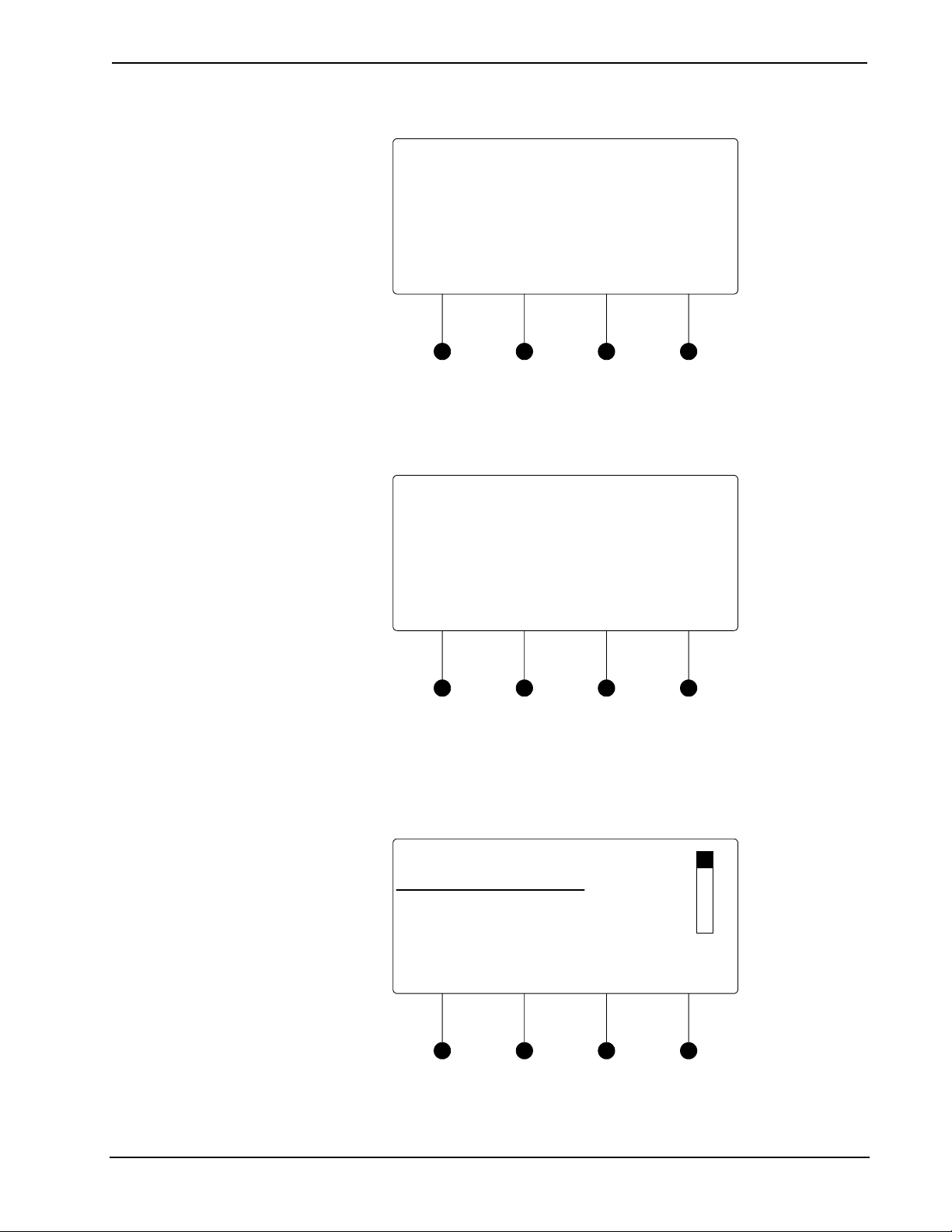
Crestron DM-MD8X8/16X16/32X32 DigitalMedia™ Switchers
Confirmation for HDCP Check
HDCP Check
The HDCP check will result
in all current routes being
cleared. Continue?
No Yes
Running an HDCP check will disconnect any audio and video routes th at
are currently set. To proceed with the HDCP check, press the soft button
labeled Yes. To cancel the HDCP check, press the soft button labeled No.
Instructions for HDCP Check
HDCP Check
Please verify that all sources
and endpoints are powered
on before proceeding.
OK
3. Verify that all source and display devices are powered on. Press the soft
button labeled OK to continue.
4. The display will show the input cards that will be tested. Press the soft
button labeled OK to begin the HDCP check.
Analysis of Cards to Be Tested
HDCP Check Status
1. Non-HDCP Card
2. Non-HDCP Card
3. Will Be Tested
Back OK
A progress bar will be displayed to show the progress of the HDCP check.
Operations Guide – DOC. 6755C DigitalMedia™ Switchers: DM-MD8X8/16X16/32X32 • 55
Page 62

DigitalMedia™ Switchers Crestron DM-MD8X8/16X16/32X32
HDCP Check in Progress
HDCP Check
Test in Progress...
OK
When the check is complete the results will be displayed.
HDCP Check Results
HDCP Check PASSED
All devices can be routed
to all outputs simultaneously
Press LIST to see results
DONE LIST
If the number of displays in use exceeds the number of devices supported
by the source, an error message will be displayed. To view the results for
each input source, press the soft button labeled LIST. Otherwise, press the
soft button labeled DONE to return to the Commission System section.
• View HDCP Check Results
HDCP Check Results
HDCP Check Results
Input 1 (DVD)
Max HDCP Keys: 9
Possible Destinations: 8
DONE << >>
a. Press the soft buttons labeled gg and hh to scroll through the results
for other inputs.
56 • DigitalMedia™ Switchers: DM-MD8X8/16X16/32X32 Operations Guide – DOC. 6755C
Page 63

Crestron DM-MD8X8/16X16/32X32 DigitalMedia™ Switchers
b. Press the soft button labeled DONE to return to the Commission
System section.
Data Rate Check
The switcher can test the cable run on each output to determine the maximum data
rate that can be delivered. To run a data rate check:
1. Open the Commission System section as described on page 54.
2. Turn the selection knob to highlight Data Rate Check and press the
ENTER button. A screen showing available cable types will be displayed.
Confirm DM Cable Type
Confirm DM Cable Type
* Digital Media
Category 6
Category 5e
Next
Cable types that were chosen when output ports were configured (refer to
“DM CAT Output Information” on page 176) and selected for testing are
shown with an asterisk (*).
3. If necessary, turn the selection knob to highlight the cable type to be tested
and press the ENTER button to confirm.
NOTE: Selecting a different cable type will cause the other cable types to
be deselected. The parameters of the newly selected cable type will be used
for testing the outputs specified in the next step.
4. Press the soft button labeled Next to continue.
Select Outputs to Test
Select Outputs to Test
* Kid’s Room
* Living Room
*Kitchen
All None Next
5. Turn the selection knob to highlight an output for testing and press the
ENTER button to mark it. Outputs to be tested are marked with an asterisk
(*).
To test all of the outputs, press the soft button labeled All.
Operations Guide – DOC. 6755C DigitalMedia™ Switchers: DM-MD8X8/16X16/32X32 • 57
Page 64

DigitalMedia™ Switchers Crestron DM-MD8X8/16X16/32X32
To remove all of the outputs from the test list, press the soft button labeled
None.
To remove an output from the test, highlight the output with the selection
knob and press the ENTER button.
NOTE: If an output uses a cable type that is different than the cable type
selected in the previous step, remove it from the list of outputs to be tested.
Repeat the data rate check using the installed cable type.
After the outputs to be tested are selected, press the soft button labeled
Next.
6. Verify that all sources and selected outputs are powered on and press the
soft button labeled OK to begin the data rate check. A progress bar will be
displayed to show the progress of the data rate check.
Data Rate Check in Progress
Data Rate Check
Test in Progress...
OK
When the test is complete the results will be displayed.
Data Rate Check Results-Success
Data Rate Check - Success
Kid’s Room – 2.22Gbps
Living Room – 3.60Gbps
Kitchen – 2.22Gbps
Resolution Done
If an error was encountered during the data rate check, an error message
will be displayed.
58 • DigitalMedia™ Switchers: DM-MD8X8/16X16/32X32 Operations Guide – DOC. 6755C
Page 65

Crestron DM-MD8X8/16X16/32X32 DigitalMedia™ Switchers
Data Rate Check Results-Error
Data Rate Check - Error
Kid’s Room – No Video
Living Room – No Video
Kitchen – 2.22Gbps
Resolution Done
7. Turn the selection knob to scroll through the test results. To view the results
expressed in resolution, press the soft button labeled Resolution. To view
the results in terms of data rate, press the soft button labeled Data Rate.
8. Press the soft button labeled Done to return to the Commission System
section.
EDID
EDID is a piece of data that HDMI receivers use to indicate their capabilities to the
HDMI sources.
The DM switcher routes DigitalMedia (DM) signals from any of the input cards to
one or more of the output channels. According to the HDMI standard, HDMI sources
are expected to only deliver audio and video formats that are supported by the
destination. To do this, the DM switcher reads the EDID information from devices
connected to the outputs and determines the video resolutions and audio format to
send to the input cards to program EDID on the input card receivers.
Using Crestron Toolbox, the DM switcher can be configured to use several different
algorithms to determine what EDID information is sent to each source:
• Copy Display
Copy Display
The EDID information from a DigitalMedia or HDMI output is copied to
the input verbatim. This means that all resolution, audio and vendor
information will be from that display.
Operations Guide – DOC. 6755C DigitalMedia™ Switchers: DM-MD8X8/16X16/32X32 • 59
Page 66

DigitalMedia™ Switchers Crestron DM-MD8X8/16X16/32X32
• Best Common
Best Common
Only resolutions that are available in all of the displays that are connected
will be transmitted to the source. This ensures that any video signal coming
in from the source will be able to be shown on all displays. If certain
resolutions are only available on a subset of the displays, they will be
omitted.
• Manual
Use Crestron Toolbox to select which resolutions are transmitted to the
source.
“Best Common” is initially set to use information from all displays, but can be
modified to use information from just a subset of displays by deselecting them in
Crestron Toolbox.
By managing which displays are used for the EDID calculations, you can maximize
the resolution of each source while ensuring that the source can be shown on each
display where it is needed.
The EDID calculations also affect audio formats. Each HDMI receiver sends its
supported audio formats to the source in the following format:
<Format> <Maximum # of channels> <sampling freq supported>
For example, a 5.1channel audio processor may have the following audio EDID
information:
• Linear PCM, 2ch, 32/44.1/48kHz
• AC3, 6ch, 32/44.1/48kHz
• DTS, 6ch, 32/44.1/48kHz
Under “Best Common”, the same rules apply to audio as video.
For more information, refer to the Crestron Toolbox help file.
60 • DigitalMedia™ Switchers: DM-MD8X8/16X16/32X32 Operations Guide – DOC. 6755C
Page 67

Crestron DM-MD8X8/16X16/32X32 DigitalMedia™ Switchers
Programming Software
Have a question or comment about Crestron software?
Answers to frequently asked questions (FAQs) can be viewed in the Online Help
section of the Crestron website. To post a question or vie w questions you have
submitted to Crestron’s True Blue Support, log in at
First-time users will need to establish a user account.
Earliest Version Software Requirements for the PC
NOTE: Crestron recommends that you use the latest software to take advantage of
the most recently released features. The latest software is available from the Crestron
website.
Crestron has developed an assortment of Windows®-based software tools to develop
a DigitalMedia system. You can create a program to control a DM switcher using the
Crestron programming tools Crestron SystemBuilder or SIMPL Windows. For the
minimum recommended software versions, visit the Version Tracker page of the
Crestron website (www.crestron.com/versiontracker).
www.crestron.com/support.
Configuration Manager
Programming with Crestron SystemBuilder
Crestron SystemBuilder™ is the easiest method of programming but does not offer
as much flexibility as SIMPL Windows. For additional details, download
SystemBuilder from the Crestron website and examine the extensive help file.
Any program created for a DM switcher with SystemBuilder will include the out-ofthe-box functionality in addition to any additional prog ramming created with
SystemBuilder.
Programming with SIMPL Windows
SIMPL Windows is Crestron’s premier software for programming Crestron control
systems. It is organized into two separate but equally important “Managers”.
Configuration Manager is the view where programmers “build” a Crestron control
system by selecting hardware from the Device Library.
1. To incorporate a DM switcher into the system, drag the desired DM
switcher from the DigitalMedia | DM Midpoints folder of the Device
Library and drop it in the System Views.
Operations Guide – DOC. 6755C DigitalMedia™ Switchers: DM-MD8X8/16X16/32X32 • 61
Page 68

DigitalMedia™ Switchers Crestron DM-MD8X8/16X16/32X32
Locating DM Switchers in the Device Library
2. The system tree of the control system displays the device in the appropriate
slot with a default IP ID as shown in the following illustration.
C2ENET-1 Net Device, Slot 8 (DM-MD8X8 shown)
3. Additional DM switchers are assigned di fferent IP ID numbers as they are
added.
4. If necessary, double click a device to open the “Device Settings” window
and change the IP ID as shown in the following figure.
“Device Settings” Window (DM-MD8X8 shown)
62 • DigitalMedia™ Switchers: DM-MD8X8/16X16/32X32 Operations Guide – DOC. 6755C
Page 69

Crestron DM-MD8X8/16X16/32X32 DigitalMedia™ Switchers
5. The ID code specified in the SIMPL Windows program must match the IP
ID of each unit. Refer to “Identity Code” on page 32.
IP Table Options
DigitalMedia devices like the DM-RMC-100 that receive their IP address
configuration via the switcher can also receive their IP table configuration from the
DM switcher or have their IP table manually configured. Depending on the
application, add DM devices as described below:
• Scenario 1: Control Center with Control System, DM switcher and
DM-RMC-100 Room Controller; Automatic IP Table Configuration
Control Center Containing Control System, DM Switcher and DM-RMC-100
Room Controller
Control
System
Ethernet DMNet
DM Switcher DM-RMC-100
To configure a SIMPL Windows program for this layout, drop
DM-RMC-100-F devices onto the output cards that are on the DM-Switcher
as shown in the following diagram. The IP table of each DM-RMC-100-F
will be automatically configured and uploaded.
Operations Guide – DOC. 6755C DigitalMedia™ Switchers: DM-MD8X8/16X16/32X32 • 63
Page 70

DigitalMedia™ Switchers Crestron DM-MD8X8/16X16/32X32
DM-RMC-100-Fs Placed on DMCO-10 Outputs
64 • DigitalMedia™ Switchers: DM-MD8X8/16X16/32X32 Operations Guide – DOC. 6755C
Page 71

Crestron DM-MD8X8/16X16/32X32 DigitalMedia™ Switchers
• Scenario 2: Control Center with Control System and DM switcher and
DM-RMC-100 Room Controller; Automatic IP Table Configuration
Control Center Containing Control System and DM Switcher Operating with
Classroom Containing Control System and DM-RMC-100 Room Controller
Program Manager
Classroom
Control Center
Control
System
Ethernet DMNet
Control
System
Ethernet
Ethernet
DM-RMC-100
DM Switcher
To configure a SIMPL Windows program for this layout, drop
DM-RMC-100-F devices onto the control system’s Ethernet slot. The IP
table of each DM-RMC-100-F will require manual configuration.
Program Manager is the view where programmers “program” a Crestron control
system by assigning signals to symbols.
The symbol can be viewed by double clicking on the icon or dragging it into Detail
View. Each signal in the symbol is described in the SIMPL Windows help file (F1).
Example Program
Example programs for the DM-MD8X8, DM-MD16X16 and DM-MD32X32 are
available from the Crestron website (
www.crestron.com/exampleprograms).
Operations Guide – DOC. 6755C DigitalMedia™ Switchers: DM-MD8X8/16X16/32X32 • 65
Page 72

DigitalMedia™ Switchers Crestron DM-MD8X8/16X16/32X32
Uploading and Upgrading
Crestron recommends using the latest programming software and that each device
contains the latest firmware to take advantage of the most recently released features.
However, before attempting to upload or upgrade it is necessary to establish
communication. Once communication has been esta bl i shed, files (for example,
programs or firmware) can be transferred to the control system (and/or device).
Finally, program checks can be performed (such as changing the device ID or
creating an IP table) to ensure proper functioning.
Establishing Communication
Use Crestron Toolbox for communicating with the DM switcher; refer to the
Crestron Toolbox help file for details. There are two methods of communication.
USB
TCP/IP
NOTE: Required for initial setup of Ethernet parameters.
USB Communication
PC Running
Crestron Toolbox
USB
DM Switcher
The COMPUTER port on the DM switcher connects to the USB port on the PC via
the included Type A to Type B USB cable.
1. Use the Address Book in Crestron Toolbox to create an entry using the
expected communication protocol (USB). When multiple USB devices are
connected, identify the DM switcher by entering “DM-MD8X8”,
“DM-MD16X16”, or “DM-MD32X32” in the Model textbox, the unit is
serial number in the Serial textbox or the unit is hostname in the Hostname
textbox. The hostname can be found in the “System Info” window in the
section marked Ethernet however, communications must be established in
order to see this information in the “System Info” window.
2. Display the DM switcher’s “System Info” window (click the
icon);
communications are confirmed when the device information is displayed.
NOTE: Required for operation with a Crestron control system.
Ethernet Communication
PC Running
Crestron Toolbox
Ethernet
DM Switcher
1. Establish USB communication between the DM switcher and PC.
2. Enter the IP address, IP mask and default router of the DM switcher via the
Crestron Toolbox (Functions | Ethernet Addressing); otherwise enable
DHCP.
66 • DigitalMedia™ Switchers: DM-MD8X8/16X16/32X32 Operations Guide – DOC. 6755C
Page 73

Crestron DM-MD8X8/16X16/32X32 DigitalMedia™ Switchers
NOTE: Use the Device Discovery Tool in Crestron Toolbox to detect all
Ethernet devices on the network and their IP configuration. The tool is
available in Toolbox version 1.15.143 or later.
3. Confirm Ethernet connections between the DM switcher and PC. If
connecting through a hub or router, use CAT5 straight through cab les with
8-pin RJ-45 connectors. Alternatively, use a CAT5 crossover cable to
connect the two LAN ports directly without using a hub or router.
4. Use the Address Book in Crestron Toolbox to create an entry for the
DM-MD8X8, DM-MD16X16, or DM-MD 3 2X 3 2 with the DM switcher ’s
TCP/IP communication parameters.
SIMPL Windows
Firmware
5. Display the “System Info” window (click the
switcher’s entry.
icon) and select the DM
Programs and Firmware
Program or firmware files may be distributed from programmers to installers or from
Crestron to dealers. Firmware upgrades are available from the Crestron website as
new features are developed after product releases. One has the option to upload
programs via the programming software or to upload and upgrade via the Crestron
Toolbox. For details on uploading and upgrading, re fer to the SIMPL Windows help
file or the Crestron Toolbox help file.
If a SIMPL Windows program is provided, it can be uploaded to the control system
using SIMPL Windows or Crestron Toolbox.
Check the Crestron website to find the latest firmware. (New users may be required
to register to obtain access to certain areas of the site, including the FTP site.)
Upgrade the DM switcher’s firmware via Crestron Toolbox.
1. Establish communication with the DM switcher and display the “System
Info” window.
2. Select Functions | Firmware… to upgrade the DM switcher’s firmware.
Program Checks
Actions that can be performed on a DM switcher vary depending on whether it is
connected via USB or Ethernet.
USB Connections
Ethernet Connections
Operations Guide – DOC. 6755C DigitalMedia™ Switchers: DM-MD8X8/16X16/32X32 • 67
For USB connections, using Crestron Toolbox, display the “System Info” wind ow
(click the
performed on the DM switcher.
For Ethernet connections, using Crestron Toolbox, display the “System Info”
window (click the
can be performed on the DM switcher.
Be sure to use Crestron Toolbox to create the DM switcher’s IP table.
1. Select Functions | IP Table Setup.
2. Add, modify or delete entries in the IP table. The DM switcher can have
3. A defined IP table can be saved to a file or sent to the device.
icon) and select the Functions menu to display actions that can be
icon) and select the Functions menu to display actions that
only one IP table entry.
Page 74

DigitalMedia™ Switchers Crestron DM-MD8X8/16X16/32X32
Edit the control system’s IP table to include an entry for the DM switcher. The entry
should list the DM switcher’s IP ID (specified on the DM switcher’s IP table) and
the internal gateway IP address 127.0.0.1.
DM Tool
In the Crestron Toolbox Address Book, select the DM switcher. Then use the DM
Tool to configure EDID, HDCP or to troubleshoot AV on the DM switcher. Refer to
the help file for additional information.
DM Tool
68 • DigitalMedia™ Switchers: DM-MD8X8/16X16/32X32 Operations Guide – DOC. 6755C
Page 75

Crestron DM-MD8X8/16X16/32X32 DigitalMedia™ Switchers
Operation
Operating Modes
A DM switcher can operate in the Route mode, the View mode, or the Info mode.
The DM switcher can also be controlled from Crestron Toolbox. For more
information, refer to the Crestron Toolbox help file.
Route Mode
View Mode
Info Mode
Switch Audio, Video, and
USB Simultaneously
The Route mode uses the front panel controls to route input signals to outputs. Press
the ROUTE button to activate the Route mode.
• When in the Route mode, pressing an input button will show the outputs
that are connected to the input.
• Audio, video, and USB portions of an i np ut can be routed independently.
For more information, refer to “Route Mode” below.
The View mode uses the front panel controls to view routing information for inputs
and outputs.
Routing information for audio, video, and USB portions of an input can be viewed
independently. For more information, refer to “View Mode” on page 70.
The Info mode uses the front panel controls to view data about signals that are
passed through the inputs and outputs of the DM switch er. For more information,
refer to “Info Mode” on page 71.
Route Mode
Signals coming in to the DM switcher can be switched to single or multiple outputs.
Additionally, the audio, video, and USB portions of an input signal can be switch ed
simultaneously or separately.
To enter the Route mode, press the ROUTE button. The ROUTE LED will light.
1. Press the AUDIO, VIDEO, and USB buttons to select the audio, video, and
USB portions for switching. The respective LEDS will light.
NOTE: If an output has different audio, video, or USB portions, a new
route will cause the audio and USB portions on the output to switch to the
newly selected video input.
2. Press the button corresponding to the input to be switched. The LED of the
selected input will light.
To turn off an output, deselect the input. The display will show “IN None”
and the input LEDs will be extinguished.
3. Press the button(s) corresponding to the output(s) to be switched. The
LED(s) of the selected output(s) will flash.
If a button press will result in changing the current routing, the LEDs of the
newly selected outputs will flash and the display will state “Press ENTER
to Route”.
4. Press ENTER to make the connection(s) shown on the front panel.
Operations Guide – DOC. 6755C DigitalMedia™ Switchers: DM-MD8X8/16X16/32X32 • 69
Page 76

DigitalMedia™ Switchers Crestron DM-MD8X8/16X16/32X32
Changes made on the front panel are made only after the ENTER button is
pressed. If you do not press ENTER, the connection is not made.
Only one input can be routed at a time. Pressing a different input button will
lose any routing plans that were not confirmed by pressing the ENTER
button.
NOTE: If ENTER has not been pressed, you can go back and “undo”
changes made to the current routing.
5. Repeat for any other routes to be changed.
Switch Audio, Video & USB
Separately
1. Press the AUDIO, VIDEO, or USB buttons to select the audio, video, or
USB portions to be switched. The respective LEDS will light.
NOTE: When audio is switched independently, the signal is 2-channel
audio.
2. Press the button corresponding to the input to be switched. The LED of the
selected input will light.
To turn off an output, deselect the input. The display will show “IN None”
and the input LEDs will be extinguished.
3. Press the button(s) corresponding to the output(s) to be switched. The
LED(s) of the selected output(s) will light.
If a button press will result in changing the current routing, the LEDs of the
newly selected outputs will flash and the display will state “Press ENTER
to Route”.
4. Press ENTER to make the connection(s) shown on the front panel.
Changes made on the front panel are made only after the ENTER button is
pressed. If you do not press ENTER, the connection is not made.
Only one input can be routed at a time. Pressing a different input button will
lose any routing plans that were not confirmed by pressing the ENTER
button.
NOTE: If ENTER has not been pressed, you can go back and “undo”
changes made to the current routing.
5. Repeat for any other routes to be changed.
View Mode
Use the View Mode to view routing information for inputs and outputs. To select the
View mode, press the VIEW button.
View Source Routing
View Output Routing
70 • DigitalMedia™ Switchers: DM-MD8X8/16X16/32X32 Operations Guide – DOC. 6755C
1. Press an input signal button to display all of the outputs that are connected
to it.
2. Press AUDIO, VIDEO, or USB to see where the audio, video, or USB
portions of an input signal are routed.
1. Press an output signal button to display the input signal that is connected.
All outputs that are receiving the same input signal are also displayed.
2. Press AUDIO, VIDEO, or USB to see the input that is providing the audio,
video, or USB portions of the output sig nal.
Page 77

Crestron DM-MD8X8/16X16/32X32 DigitalMedia™ Switchers
Info Mode
Use the Info mode to view information about the signal on an input or output.
Depending on the input selected, available information can include the name of the
input, the detected resolution, the detected video type, the detected frame rate, the
detected aspect ratio, the HDCP state, and the deep color setting. To select the Info
mode, press the INFO button. If an input port is receiving a signal from its
connected source, the accompanying LED will illuminate.
View Input Information
View Output Information
1. Press an input button to display information about the input signal. The
accompanying LED will flash.
NOTE: If the DMC-VID4 is selected, each composite video input can be
selected for viewing by pressing the soft button of the desired input.
2. Turn the selection knob to display available information.
3. Press another input button to view its information.
1. Press an output button to display information about the output signal. The
accompanying LED will flash.
NOTE: If a DM output with HDMI is selected, information for the DM
port and the HDMI port can be selected for viewing by pressing the soft
button of the desired output.
2. Turn the selection knob to display available information.
3. Press another output button to view its information.
Operations Guide – DOC. 6755C DigitalMedia™ Switchers: DM-MD8X8/16X16/32X32 • 71
Page 78

DigitalMedia™ Switchers Crestron DM-MD8X8/16X16/32X32
Problem Solving
Troubleshooting
The following table provides corrective action for possible trouble situations. If
further assistance is required, please contact a Crestron customer service
representative.
DM Switcher Troubleshooting
TROUBLE POSSIBLE CAUSE(S) CORRECTIVE ACTION
Incorrect Audio or
Video displayed.
Distorted audio or
video.
No video.
Bandwidth check
passes and
LED on
DM-RMC-100 is lit.
No video displayed,
but audio is heard.
HDCP Check
Failure Message
during
commissioning.
Bandwidth Test
Failure Message
during
commissioning.
DM-DR Repeater
or DM-RMC-100
Room Controller do
not report to DM
switcher.
No audio output
from RCA
connectors on
DMC-HD
Loss of
functionality due to
electrostatic
discharge.
VIDEO
Audio is routed
separately from video.
Source does not match
capabilities of
destination.
“D” cable is incorrectly
terminated.
Possible HDCP error.
Violation of HDCP rules
(number of display
devices exceeds the
source’s number of
allowed displays).
Violation of HDCP rules
(device depth exceeds
allowable depth
specification).
Poor cable connection to
a DM-RMC-100 (on the
“D” line).
Poor cable connection to
the DM-DR or
DM-RMC-100 (on the “D”
line).
Source is not providing a
2-channel audio signal.
Improper grounding.
Reroute audio together with
video.
Use Crestron Toolbox to
manage EDID capabilities of
devices in the system.
Terminate cable as described
in “DigitalMedia Cable” on
page 28.
Check control system error
log, or DM switch for HDCP
errors.
Disconnect displays that may
not be used with source during
run time and repeat HDCP
check.
Replace source device with a
device that allows more
displays to be connected.
Reconfigure signal path to
remove midpoint devices that
increase overall device depth.
Verify that cable is not crimped
or damaged.
Verify that cable is not crimped
or damaged.
Replace DMC-HD card with
DMC-HD-DSP to provide
2-channel stereo downmix
from audio source.
Check that all ground
connections have been made
properly.
72 • DigitalMedia™ Switchers: DM-MD8X8/16X16/32X32 Operations Guide – DOC. 6755C
Page 79

Crestron DM-MD8X8/16X16/32X32 DigitalMedia™ Switchers
Check Network Wiring
Use the Right Wire
Calculate Power
In order to ensure optimum performance over the full range of your installation
topology, Crestron Certified Wire and only Crestron Certified Wire may be used.
Failure to do so may incur additional charges if support is required to identify
performance deficiencies because of using improper wire.
CAUTION: Use only Crestron power supplies for Crestron equipment. Failure to
do so could cause equipment damage or void the Crestron warranty.
CAUTION: Provide sufficient power to the system. Insufficient power can lead to
unpredictable results or damage to the equipment. The EIG connector on the DM
switcher is used to bring in external power. Additional power is rarely required as
switchers provide enough power for their maximum configuration of room
controllers and repeaters. Please use the DMNet Power Calculator to help calculate
how much power is needed for the system (
CresFiber fiber optic cables provide for longe r distances bet ween the DigitalMedia
switcher and a DigitalMedia Room Controller. For more information, refer to the
latest version of the Crestron DigitalMedia Design Guide (Doc. 4789).
Refer to the following tables for maximum cable lengths using various cables.
Maximum DM Cable Length
Cable Type: DM-CBL DigitalMedia Cable
Maximum length
without, between,
before or after
Resolution:
720p, 1080i, 1080p24 200 ft (60 m)
1024x768 @ 75 Hz 200 ft (60 m) 450 ft (137 m)
1080p60 150 ft (45 m) 450 ft (137 m)
1280x1024 @ 75 Hz 150 ft (45 m) 450 ft (137 m)
1920x1200 @ 60 Hz 150 ft (45 m) 450 ft (137 m)
1600x1200 @ 60 Hz 125 ft (38 m) 375 ft (114 m)
1080p60 Deep Color 100 ft (30 m) 300 ft (91 m)
repeaters
www.crestron.com/calculators).
Maximum total
length using up
to 2 repeaters
450 ft (137 m)
NOTE: All Crestron certified DMNet wiring must consist of two twisted pairs. One
twisted pair is the +24V conductor and the GND conductor and the other twisted pair
is the A conductor and the B conductor.
Operations Guide – DOC. 6755C DigitalMedia™ Switchers: DM-MD8X8/16X16/32X32 • 73
Page 80

DigitalMedia™ Switchers Crestron DM-MD8X8/16X16/32X32
Maximum CresFiber Cable Length
RESOLUTION CRESFIBER
720p, 1080i, 1080p24
1024 x 768 @ 75 Hz
1280 x 1024 @ 75 Hz
1600 x 1200 @ 60 Hz
1920 x 1200 @ 60 Hz
1080p60
1080p60 Deep Color
Other fiber optic cable can be used as well.
NOTE: 1080p60 is the most common resolution used in residential installations.
1000’
(~300 m)
Reference Documents
The latest version of all documents mentioned within the guide can be obtained from
the Crestron website (www.crestron.com/manuals). This link will provide a list of
product manuals arranged in alphabetical order by model number.
List of Related Reference Documents
DOCUMENT TITLE
Crestron DigitalMedia Design Guide
Crestron e-Control Reference Guide
Further Inquiries
If you cannot locate specific information or have questions after reviewing this
guide, please take advantage of Crestron's award winning customer service team by
calling Crestron at 1-888-CRESTRON [1-888-273-7876].
You can also log onto the online help section of the Crestron website
(
www.crestron.com/onlinehelp) to ask questions about Crestron products. First-time
users will need to establish a user account to fully benefit from all available features.
Future Updates
As Crestron improves functions, adds new features and extends the capabilities of
DM switchers, additional information may be made available as manual updates.
These updates are solely electronic and serve as intermediary supplements prior to
the release of a complete technical documentation revision.
Check the Crestron website periodically for manual update availability and its
relevance. Updates are identified as an “Addendum” in the Download column.
74 • DigitalMedia™ Switchers: DM-MD8X8/16X16/32X32 Operations Guide – DOC. 6755C
Page 81

Crestron DM-MD8X8/16X16/32X32 DigitalMedia™ Switchers
Appendix A: Hardware Hookup for DM Cards
This section contains information for connecting sources and other devices to input
and output cards installed on a DM switcher. For installation instructions, refer to the
latest version of the card’s Installation Guide.
Input Cards
This section contains information on the following input cards:
• DMC-CAT DM CAT Input Card for DM Switchers below.
• DMC-CAT-DSP DM CAT Input Card with Down-mixing for DM
Switchers on page 76.
• DMC-DVI DVI/RGB Input Card for DM Switchers on page 77.
• DMC-F DM Fiber Input Card for DM Switchers on pa ge 7 9.
• DMC-F-DSP DM Fiber Input Card with Down-mixing for DM Switchers
on page 80.
DMC-CAT DM CAT Input
Card for DM Switchers
• DMC-HD HDMI Input Card for DM Switchers on page 81.
• DMC-HD-DSP HDMI Input Card with DSP for DM Switchers on page 82.
• DMC-SDI SDI Input Card for DM Switchers on page 83.
• DMC-VID4 Security Camera Input Card for DM Switchers on page 84.
• DMC-VID-BNC BNC Analog Video Input Card for DM Switchers on page
84.
• DMC-VID-RCA-A RCA Analog Video Input Card with Analog Audio for
DM Switchers on page 86.
• DMC-VID-RCA-D RCA Analog Video Input Card with Digital Audio for
DM Switchers on page 86.
Connections for output cards can be found on page 87.
Refer to the following diagrams when connecting sources to DM input cards.
The DMC-CAT is an input card for a DigitalMedia switcher, providing one
CAT-type DM input. The DM CAT input enables the connection of a DM
transmitter or the output of another DM switcher, with a potential cable length up to
450 feet (137 m) using DigitalMedia cable.
NOTE: For optimum performance, Crestron recommends Crestron DigitalMedia
cable.
Additional connections on the card include both HDMI and stereo analog audio
loopback outputs. The HDMI output passes the input signal through to feed a local
device, or to feed a second DM switcher for output expansion purposes. The analog
audio output, which features pro gram mable volume control, breaks out the stereo
audio signal from the HDMI input and passes it through to feed a CNX-PAD8A,
AAE, or other multi-room audio di st ri b ut i o n syst em.
NOTE: For applications requiring the simultaneous distribution of surround sound
and 2-channel audio signals, use model DMC-CAT-DSP.
Operations Guide – DOC. 6755C DigitalMedia™ Switchers: DM-MD8X8/16X16/32X32 • 75
Page 82

DigitalMedia™ Switchers Crestron DM-MD8X8/16X16/32X32
The DMC-CAT may also be used with the DMCI DigitalMedia Card Interface to
provide a DM CAT receiver solution that is perfect for installation in an equipment
rack or AV cart, or as a portable display interface. As a DM receiver, and as a DM
switcher input card, the DMC-CAT enables EDID signal detection and format
management, CEC device control, and audio breakaway.
Hardware Hookup for DMC-CAT DM CAT Input Card for DM Switchers
DMC-CAT-DSP DM CAT
Input Card with Down-mixing
for DM Switchers
From DigitalMedia
Transmitter or DigitalMedia
HDMI OUT:
To Local HD Display or HDMI
Input on Daisy-Chained DM
Switcher
DM:
Switcher
NET:
From DigitalMedia
Transmitter or DigitalMedia
Switcher
AUDIO OUT:
To 2-Channel Audio
Input
The DMC-CAT-DSP is an input card for a DigitalMedia switcher, providing one
CAT-type DM input. The DM CAT input enables the connection of a DM
transmitter or the output of another DM switcher, with a potential cable length up to
450 feet (137 m) using DigitalMedia cable.
NOTE: For optimum performance, Crestron recommends Crestron DigitalMedia
cable.
The DMC-CAT-DSP provides all of the features of the DMC-CAT with the addition
of internal DSP processing to enable the simultaneous distribution of uncompressed
7.1 channel HD surround sound and 2-channel audio. The DMC-CAT-DSP is
recommended for use with Blu-ray Disc players and other HD sources that output
multi-channel surround sound audio via HDMI, allowing the multi-channel signal to
reach the surround sound system without requiring any decoding, while also
providing a 2-channel down-mix to feed a stereo zone or audio distribution system.
Additional connections on the card include both HDMI and stereo analog audio loop
back outputs. The HDMI output simp ly passes the input signal through to feed a
local device, or to feed a second DM switcher for output expansion purposes. The
analog audio output, which features programmable volume control, breaks out the
stereo audio signal from the HDMI input and passes it through to feed a
CNX-PAD8A, AAE, or other multi-room audio distribution system.
The DMC-CAT-DSP may also be used with the DMCI DigitalMedia Card Interface
to provide a DM CAT receiver solution that is perfect for installation in an
equipment rack or AV cart, or as a portable display interface. As a DM receiver, and
as a DM switcher input card, the DMC-CAT-DSP enables EDID signal detection
and format management, CEC device control, and audio breakaway.
76 • DigitalMedia™ Switchers: DM-MD8X8/16X16/32X32 Operations Guide – DOC. 6755C
Page 83

Crestron DM-MD8X8/16X16/32X32 DigitalMedia™ Switchers
Hardware Hookup for DMC-CAT-DSP DM CAT Input Card with Down-mixing for DM
Switchers
DMC-DVI DVI/RGB Input
Card for DM Switchers
From DigitalMedia
Transmitter or DigitalMedia
HDMI OUT:
To Local HD Display or HDMI
Input on Daisy-Chained DM
Switcher
DM:
Switcher
NET:
From DigitalMedia
Transmitter or DigitalMedia
Switcher
AUDIO OUT:
To 2-Channel Audio
Input
The DMC-DVI is an input card for a DigitalMedia switcher, providing one DVI
digital video input or analog RGB/Component input, with balanced stereo analog
audio. The DMC-DVI handles computer resolutions up to WUXGA 1920 x 1200, as
well as HDTV up to 1080p60. Professional balanced/unbalanced audio inputs are
included to accept a stereo line level audio signal.
NOTE: DVI-I connection requires an appropriate adapter to accommodate an RGB
or YPbPr signal. (1) RGB-to-DVI-I adapter is included. YPbPr adapter not included.
Additional connections on the card include an HDMI loop back output, and a USB
HID port. The HDMI output passes the audio and vi deo input si g nal s thr ou g h
digitally to feed a local device, or to feed a second DM switcher for output
expansion purposes. The USB HID host port allows a remote mouse/keyboard
connected at the display location, to control a centralized source device (i.e.
computer, media server, etc.) at the equipment rack.
Operations Guide – DOC. 6755C DigitalMedia™ Switchers: DM-MD8X8/16X16/32X32 • 77
Page 84

DigitalMedia™ Switchers Crestron DM-MD8X8/16X16/32X32
Hardware Hookup for DMC- DVI Input Card for DM Switchers
AUDIO IN:
From Analog Audio
Output
From DVI or RGB Source
HDMI OUT:
To Local HD Display or HDMI
Input on Daisy-Chained DM
Switcher
DVI IN:
USB HID:
To PC Source
Balanced/unbalanced audio inputs are provided, utilizing five-pin terminal block
connectors. For connection details, refer to the following table and diagrams.
Audio Connections
SIGNAL NAME BALANCED AUDIO INPUT UNBALANCED AUDIO INPUT
+ L + L +
- L - L – signal return, jumper to GND
G Shield/Ground Ground
+ R + R +
- R - R – signal return, jumper to GND
Typical Balanced/Unbalanced Inputs
Balanced
Input
Shield
Left
Right
L R
+ - G + -
+
+
Unbalanced
Input
Left
Right
L R
+ - G + -
+
Shield
+
Shield
Jumpers
78 • DigitalMedia™ Switchers: DM-MD8X8/16X16/32X32 Operations Guide – DOC. 6755C
Page 85

Crestron DM-MD8X8/16X16/32X32 DigitalMedia™ Switchers
The BNC output of a wideband RGB switcher such as the Crestron
CEN-RGBHV12X4 can be connected to a DMC-DVI using either a BNC-to-DVI
adapter (not included) or a BNC-VGA adapter (not included) with the included
VGA-DVI adapter to provide further expansion. When connecting sources to the
switcher, please make the following connections.
Hardware Hookup, BNC to DVI
DMC-F DM Fiber Input Card
for DM Switchers
Port Connections
SIGNAL TYPE INPUT SIGNAL CONNECTS TO
RGBHV
YPbPr
Composite Composite B
R R
G G
B B
H H
V V
Y G
Pb B
Pr R
C R S-video
Y G
The DMC-F is an input card for a DigitalMedia switcher, providing one optical fiber
type DM input. The DM fiber input enables the connection of a DM transmitter, or
the output of another DM switcher, with a potential cable length up to 1000 feet
(300 m) using multimode fiber optic cable.
NOTE: For optimum performance, Crestron recommends Crestron DigitalMedia
cable.
Additional connections on the card include both HDMI and stereo analog audio loop
back outputs. The HDMI output simp ly passes the input signal through to feed a
local device, or to feed a second DM switcher for output expansion purposes. The
analog audio output, which features programmable volume control, breaks out the
stereo audio signal from the HDMI input and passes it through to feed a
CNX-PAD8A, AAE, or other multi-room audio distribution system.
NOTE: For applications requiring the simultaneous distribution of surround sound
and 2-channel audio signals, use model DMC-F-DSP.
Operations Guide – DOC. 6755C DigitalMedia™ Switchers: DM-MD8X8/16X16/32X32 • 79
Page 86

DigitalMedia™ Switchers Crestron DM-MD8X8/16X16/32X32
The DMC-F may also be used with the DMCI DigitalMedia Card Interface to
provide a DM fiber receiver solution that is perfect for installation in an equipment
rack or AV cart, or as a portable display interface. As a DM receiver, and as a DM
switcher input card, the DMC-F enables EDID signal detection and format
management, CEC device control, and audio breakaway.
Hardware Hookup for DMC-F DM Fiber Input Card for DM Switchers
DMC-F-DSP DM Fiber Input
Card with Down-mixing for
DM Switchers
DM:
From DigitalMedia
Transmitter or DigitalMedia
Switcher
HDMI OUT:
To Local HD Display or HDMI
Input on Daisy-Chained DM
Switcher
AUDIO OUT:
To 2-Channel Audio
Input
The DMC-F-DSP is an input card for a DigitalMedia switcher, providing one optical
fiber type DM input. The DM fiber input enables the connection of a DM
transmitter, or the output of another DM switcher, with a potential cable length up to
1000 feet (300 m) using multimode fiber optic cable.
NOTE: For optimum performance, Crestron recommends Crestron DigitalMedia
cable.
The DMC-F-DSP provides all of the features of the DMC-F with the addition of
internal DSP processing to enable the simultaneous distribution of uncompressed 7.1
channel HD surround sound and 2-channel audio. The DMC-F-DSP is recommended
for use with Blu-ray Disc players and other HD sources that output multi-channel
surround sound audio via HDMI, allowing the multi-channel signal to reach the
surround sound system without requiring any decoding, while also providing a
2-channel down-mix to feed a stereo zone or audio distribution system.
Additional connections on the card include both HDMI and stereo analog audio loop
back outputs. The HDMI output simp ly passes the input signal through to feed a
local device, or to feed a second DM switcher for output expansion purposes. The
analog audio output, which features programmable volume control, breaks out the
stereo audio signal from the HDMI input and passes it through to feed a
CNX-PAD8A, AAE, or other multi-room audio distribution system.
The DMC-F-DSP may also be used with the DMCI DigitalMedia Card Interface to
provide a DM fiber receiver solution that is perfect for installation in an equipment
rack or AV cart, or as a portable display interface. As a DM receiver, and as a DM
switcher input card, the DMC-F-DSP enables EDID signal detection and format
management, CEC device control, and audio breakaway.
80 • DigitalMedia™ Switchers: DM-MD8X8/16X16/32X32 Operations Guide – DOC. 6755C
Page 87

Crestron DM-MD8X8/16X16/32X32 DigitalMedia™ Switchers
Hardware Hookup for DMC-F-DSP DM Fiber Input Card with Down-Mixing for DM
Switchers
DMC-HD HDMI Input Card for
DM Switchers
DM:
From DigitalMedia
Transmitter or DigitalMedia
Switcher
HDMI OUT:
To Local HD Display or HDMI
Input on Daisy-Chained DM
Switcher
AUDIO OUT:
To 2-Channel Audio
Input
The DMC-HD is an input card for a DigitalMedia switcher, providing one HDMI
input. The DMC-HD supports HDMI with deep color, handling sources with
resolutions and frame rates up to 1080p60, HD lossless audio, and color depths up to
12-bit.
Additional connections on the card include an HDMI loop back output, a stereo
analog audio loop back output, and a USB HID port . The HDMI output passes the
input signal through to feed a local device, or to feed a second DM switcher for
output expansion purposes. The analog audio output breaks out the stereo audio
signal from the HDMI input and passes it through to feed a CNX-PAD8A, AAE, or
other multi-room audio distribution system.
NOTE: For applications requiring the simultaneous distribution of uncompressed
multi-channel surround sound and 2-channel audio, use model DMC-HD-DSP.
The USB HID port allows a remote mouse/keyboard connected at the display
location, to control a centralized source device (i.e. computer, media server, etc.) at
the equipment rack.
Operations Guide – DOC. 6755C DigitalMedia™ Switchers: DM-MD8X8/16X16/32X32 • 81
Page 88

DigitalMedia™ Switchers Crestron DM-MD8X8/16X16/32X32
Hardware Hookup for DMC- HD HDMI Input Card for DM Switchers
DMC-HD-DSP HDMI Input
Card with DSP for DM
Switchers
AUDIO OUT:
To 2-Channel Audio
Input
To Local HD Display or HDMI
HDMI OUT:
Input on Daisy-Chained DM
Switcher
HDMI IN:
From HDMI Source
USB HID:
To PC Source
NOTE: Audio is present on the AUDIO OUT port when 2-channel audio is present
on the HDMI input signal.
The DMC-HD-DSP is an input card for a DigitalMedia switcher, providing one
HDMI input. The DMC-HD-DSP supports HDMI with deep color, handling sources
with resolutions and frame rates up to 1080p60, HD lossless audio, and color depths
up to 12-bit.
The DMC-HD-DSP provides all of the features of the DMC-HD with the addition of
internal DSP processing to enable the simultaneous distribution of uncompressed 7.1
channel HD surround sound and 2-channel audio. The DMC-HD-DSP is
recommended for use with Blu-ray Disc players and other HD sources that output
multi-channel surround sound audio via HDMI, allowing the multi-channel signal to
reach the surround sound system without requiring any decoding, while also
providing a 2-channel down-mix to feed a stereo zone or audio distribution system.
Additional connections on the card include an HDMI loop back output, a stereo
analog audio loop back output, and a USB HID port . The HDMI output passes the
input signal through to feed a local device, or to feed a second DM switcher for
output expansion purposes. The analog audio output breaks out the stereo audio
signal from the HDMI input and passes it through to feed a CNX-PAD8A, AAE, or
other multi-room audio distribution system.
The USB HID port allows a remote mouse/keyboard connected at the display
location, to control a centralized source device (i.e. computer, media server, etc.) at
the equipment rack.
82 • DigitalMedia™ Switchers: DM-MD8X8/16X16/32X32 Operations Guide – DOC. 6755C
Page 89

Crestron DM-MD8X8/16X16/32X32 DigitalMedia™ Switchers
Hardware Hookup for DMC- HD DMC-HD-DSP HDMI Input Card with DSP for DM
Switchers
DMC-SDI SDI Input Card for
DM Switchers
AUDIO OUT:
To 2-Channel Audio
Input
To Local HD Display or HDM I
HDMI OUT:
Input on Daisy-Chained DM
Switcher
HDMI IN:
From HDMI Source
USB HID:
To PC Source
NOTE: The AUDIO OUT port contains a 2-channel downmix of the audio portion
of the HDMI input signal.
The DMC-SDI is an input card for a DigitalMedia switcher, providing one SDI input
to support a variety of professional and commercial AV sources. The DMC-SDI
supports SD-SDI, HD-SDI and 3G-SDI formats, handling high-definition video
signals up to 1080p60, and up to eight channels of 24-bit digital audio - all through a
single coaxial cable. An SDI loop-thru output is included for connection to a local
monitor or other SDI device.
Additional connections on the card include an HDMI output and a stereo analog
audio output. The HDMI output allows the converted SDI signal to be passed to a
local device, or to a second DM switcher for output expansion purposes. The analog
audio output, which features pro grammable volume control, breaks out a stereo
audio signal from the SDI input and passes it through to feed a CNX-PAD8A, AAE,
or other multi-room audio distribution system.
The DMC-SDI may also be used with the DMCI DigitalMedia Card Interface to
create a problem-solving tool with many useful functions. For instance, it can be
used to convert SDI video and audio to HDMI, or to extract an analog audio signal
from an SDI signal.
Operations Guide – DOC. 6755C DigitalMedia™ Switchers: DM-MD8X8/16X16/32X32 • 83
Page 90

DigitalMedia™ Switchers Crestron DM-MD8X8/16X16/32X32
Hardware Hookup for DMC-SDI SDI Input Card for DM Switchers
DMC-VID4 Security Camera
Input Card for DM Switchers
SDI IN:
From SDI SOURCE
HDMI OUT:
To Local HD Display or HDMI
Input on Daisy-Chained DM
Switcher
SDI OUT:
To SDI Device
AUDIO OUT:
To 2-Channel Audio
Input
The DMC-VID4 is an input card for a DigitalMedia switcher, providing four
composite video inputs with built-in sequential switching and quad processing.
The DMC-VID4 allows up to four security cameras to be viewed individually or
simultaneously in quad, dual, or full screen modes. When viewing full screen, the
input may be selected manually or sequentially. The sequential switching function
cycles automatically through each available input, displaying each source one at a
time per a user-definable duration. In any mode, dynamic colored text overlay
capability allows each window or source to be clearly identified.
DMC-VID-BNC BNC Analog
Video Input Card for DM
Switchers
A local HDMI output connection is also provided on the card, allowing the
processed video signal to be fed to a local device, or to a second DM switcher for
output expansion purposes.
Hardware Hookup for DMC-VID4 Security Camera Input Card for DM Switchers
To Local HD Display or HDMI
HDMI OUT:
Input on Daisy-Chained DM
Switcher
COMPOSITE IN:
From Composite Video
Sources
The DMC-VID-BNC is an input card for a DigitalMedia switcher, providing one
analog video input and one balanced stereo analog audio input. The DMC-VID-BNC
accepts component HDTV signals up to 1080p60, as well as standard definition
NTSC/PAL composite and S-video. An HDMI loop back output connection is also
provided, which passes the audio and video input signals through digitally to feed a
local device, or to feed a second DM switcher for output expansion purposes.
84 • DigitalMedia™ Switchers: DM-MD8X8/16X16/32X32 Operations Guide – DOC. 6755C
Page 91

Crestron DM-MD8X8/16X16/32X32 DigitalMedia™ Switchers
Hardware Hookup for DMC-BNC BNC Analog Video Input Card for DM Switchers
From YP
S-Video Source
HDMI OUT:
To Local HD Display or HDMI
Input on Daisy-Chained DM
Switcher
VIDEO IN:
, Composite or
bPr
AUDIO IN:
From Analog Audio
Output
Balanced/unbalanced audio inputs are provided, utilizing five-pin terminal block
connectors. For connection details, refer to the following table and diagrams.
Audio Connections
SIGNAL
NAME
+ L + L +
- L - L – signal return jumper to GND
G Shield/Ground Ground
+ R + R +
- R - R – signal return jumper to GND
BALANCED
AUDIO INPUT
UNBALANCED AUDIO INPUT
Typical Balanced/Unbalanced Inputs
Balanced
Input
L R
+ - G + -
Shield
+
Left
+
Right
Operations Guide – DOC. 6755C DigitalMedia™ Switchers: DM-MD8X8/16X16/32X32 • 85
Unbalanced
Input
Left
Right
L R
+ - G + -
+
Shield
+
Shield
Jumpers
Page 92

DigitalMedia™ Switchers Crestron DM-MD8X8/16X16/32X32
DMC-VID-RCA-A RCA
Analog Video Input Card with
Analog Audio for DM
Switchers
The DMC-VID-RCA-A is an input card for a DigitalMedia switcher, providing one
analog video input and one stereo analog audio input. The DMC-VID-RCA-A
accepts component HDTV signals up to 1080p, as well as standard definition
NTSC/PAL composite and S-video. An HDMI loop back output connection is also
provided, which passes the audio and video input signals through digitally to feed a
local device, or to feed a second DM switcher for output expansion purposes.
Hardware Hookup for DMC-VID-RCA-A RCA Analog Video Input Card with Analog
Audio for DM Switchers
From YP
S-Video Source
HDMI OUT:
To Local HD Display or HDMI
Input on Daisy-Chained DM
Switcher
VIDEO IN:
, Composite or
bPr
AUDIO IN:
From Analog Audio
Output
DMC-VID-RCA-D RCA
Analog Video Input Card with
Digital Audio for DM
Switchers
The DMC-VID-RCA-D is an input card for a DigitalMedia switcher, providing one
analog video input and one S/PDIF coaxial digital audio input. The
DMC-VID-RCA-D accepts component HDTV signals up to 1080p, as well as
standard definition NTSC/PAL composite and S-video. Its S/PDIF input supports
2-channel stereo and 5.1 surrou nd-encoded digital audio sources up to 24-bit,
96 kHz.
An HDMI loop back output connection is also provided, which passes the audio and
video input signals through digitally to feed a local device, or to feed a second DM
switcher for output expansion purposes.
86 • DigitalMedia™ Switchers: DM-MD8X8/16X16/32X32 Operations Guide – DOC. 6755C
Page 93

Crestron DM-MD8X8/16X16/32X32 DigitalMedia™ Switchers
Hardware Hookup for DMC-VID-RCA-D RCA Analog Video Input Card with Digital
Audio for DM Switchers
D & M Ports Using DM Cable
From YP
S-Video Source
HDMI OUT:
To Local HD Display or HDMI
Input on Daisy-Chained DM
Switcher
VIDEO IN:
, Composite or
bPr
AUDIO IN:
From Digital Audio
Output
Output Connections
A variety of output configurations are available for the DM switchers. Refer to the
following diagrams when making connections to DM output cards.
For cards equipped with DM cable connection (RJ-45) refer to the following
diagram.
Hardware Hookup for DM Cable Outputs
Operations Guide – DOC. 6755C DigitalMedia™ Switchers: DM-MD8X8/16X16/32X32 • 87
Page 94

DigitalMedia™ Switchers Crestron DM-MD8X8/16X16/32X32
D & M Ports Using DM Cable
(with Optional HDMI Output)
D & M Ports Using DM Fiber
For cards equipped with a DM cable connection (RJ-45) and an HDMI output, refer
to the following diagram.
Hardware Hookup for DM Cable Connection with HDMI Output
NOTE: The DM and HDMI ports can be connected simultaneously or individually.
For cards equipped with DM fiber connections refer to the following diagram.
Hardware Hookup for DM Fiber Outputs
DM:
To DM Receiver
DMNET:
To DM Receiver
(Optional)
NOTE: When wiring the 24ABG port, connect the 24 and G lines only. Do not
connect the A and B lines.
88 • DigitalMedia™ Switchers: DM-MD8X8/16X16/32X32 Operations Guide – DOC. 6755C
Page 95

Crestron DM-MD8X8/16X16/32X32 DigitalMedia™ Switchers
d
HDMI Outputs
For cards equipped with HDMI outputs refer to the following diagram.
Hardware Hookup for HDMI Outputs
NOTE: The analog audio output will only function if it receives a stereo audio
signal from a stereo source or a stereo downmix from a “-DSP” input card.
NOTE: If the audio from a DMC-RCA-D is routed to an HDMI output, audio will
not be present on the audio output.
Balanced/unbalanced audio outputs are provided, utilizing five-pin terminal block
connectors. For connection details, refer to the following table and diagrams.
Audio Connections
SIGNAL NAME BALANCED AUDIO OUTPUT UNBALANCED AUDIO OUTPUT
+ L + L +
- L - L – signal return, jumper to GND
G Shield/Ground Ground
+ R + R +
- R - R – signal return, jumper to GND
Typical Balanced/Unbalanced Inputs
Balanced
Output
Shield
Left
Right
L R
+ - G + -
+
+
Unbalanced
Output
Left
Right
+ - G + -
+
Shield
+
Shiel
L R
Jumpers
Operations Guide – DOC. 6755C DigitalMedia™ Switchers: DM-MD8X8/16X16/32X32 • 89
Page 96

DigitalMedia™ Switchers Crestron DM-MD8X8/16X16/32X32
Appendix B: Input Card Configuration
This appendix contains detailed instructions for using the DM switcher’s front panel
controls to configure DigitalMedia input cards that are installed in a DM switcher.
To view/change the configuration settings for an input card:
1. Open the Inputs section of Installer Tools as described on page 42.
2. Turn the selection knob to highlight the card to be configured and press the
ENTER button.
⇒ For information on configuring the DMC-CAT DM CAT Input Card
for DM Switchers, refer to “DMC-CAT” on page 91.
⇒ For information on configuring the DMC-CAT-DSP DM CAT Input
Card with DSP for DM Switchers, refer to “DMC-CAT-DSP” on page
99.
⇒ For information on configuring the DMC-DVI DVI/RGB Input Card
for DM Switchers, refer to “DMC-DVI” on page 107.
⇒ For information on configuring the DMC-F Fiber Input Card for DM
Switchers, refer to “DMC-F” on page 115.
⇒ For information on configuring the DMC-F-DSP Fiber Input Card with
DSP for DM Switchers, refer to “DMC-F-DSP” on page 121.
⇒ For information on configuring the DMC-HD HDMI Input Card for
DM Switchers, refer to “DMC-HD” on page 127.
⇒ For information on configuring the DMC-HD-DSP HDMI Input Card
with DSP for DM Switchers, refer to “DMC-HD-DSP” on page 135.
⇒ For information on configuring the DMC-SDI SDI Input Card for DM
Switchers, refer to “DMC-SDI” on page 143.
⇒ For information on configuring the DMC-VID4 Security Camera Input
Card for DM Switchers, refer to “DMC-VID4” on page 147.
⇒ For information on configuring the DMC-VID -B NC A nal o g Video
Input Card with Analog Audio for DM Switchers, refer to
“DMC-VID-BNC” on page 154.
⇒ For information on configuring the DMC-VID-RCA-A RCA Analog
Video Input Card with Analog Audio for DM Switchers, refer to
“DMC-VID-RCA-A” on page 161.
⇒ For information on configuring the DMC-VID-RCA-D RCA Analog
Video Input Card with Digital Audio for DM Switchers, refer to
“DMC-VID-RCA-D” on page 168.
90 • DigitalMedia™ Switchers: DM-MD8X8/16X16/32X32 Operations Guide – DOC. 6755C
Page 97

Crestron DM-MD8X8/16X16/32X32 DigitalMedia™ Switchers
DMC-CAT
The front panel controls for the DMC-CAT allow the user to rename the input, adjust
the picture, and view information on the incoming source and the outgoing HDMI
signal.
DMC-CAT Controls
3. DMC-CAT Basic DM I
Name: 3
Video Settings
Audio Settings
Name/Rename the Input
Using the DMC-CAT controls, the user can:
• Change the input name.
• View details on the video portion of the incoming signal
• View details on the audio portion of the incoming signal.
• View details on the signal delivered to the HDMI OUT (loopback) port.
• View details about the device connected to the HDMI OUT (loopback)
port.
• Adjust the audio output level
• Select the cable type
• View EDID settings
• Perform an HDCP check to determine how many endpoints can be
connected to the source
• Restore the default settings.
To name and/or rename the input:
1. Turn the selection knob to highlight Name and press the ENTER button. A
cursor will appear next to the current name and controls for changing the
name will also be displayed. To cancel and return to the list of options for
the input card, press the MENU button.
Operations Guide – DOC. 6755C DigitalMedia™ Switchers: DM-MD8X8/16X16/32X32 • 91
Page 98

DigitalMedia™ Switchers Crestron DM-MD8X8/16X16/32X32
Edit Input Name
Edit Input Name
PC
Del < > Done
2. Select letters (upper and lower-case), numbers, or other characters by
turning the selection knob until the desired letter, number, or other character
is displayed on the LCD. Move the cursor to another position by pressing
the soft buttons labeled g and h. To delete a character, press the soft
button marked Del.
NOTE: The maximum length for any input name is 32 characters.
Video Settings
3. After the new name has been entered, press Done to save the name and
return to the list of options for the input card.
The DMC-CAT can display information about the video portion of the incoming
signal, adjust the picture, and automatically calibrate the source to the display. To
view and/or adjust the video settings:
1. Turn the selection knob to highlight Video Settings and press the ENTER
button.
Video Settings
Video Settings
Input Type: HDMI
Video Type: Interlaced
Resolution: 1920x1080
2. Turn the selection knob to view information on input type, video type,
resolution, frame rate, and aspect ratio.
3. Press the MENU button to return to the list of options for the input card.
Audio Settings
92 • DigitalMedia™ Switchers: DM-MD8X8/16X16/32X32 Operations Guide – DOC. 6755C
The DMC-CAT can display information about the audio portion of the incoming
signal. Available information includes format, frequency, and channels. To view
audio settings:
1. Turn the selection knob to highlight Audio Settings and press the ENTER
button.
Page 99

Crestron DM-MD8X8/16X16/32X32 DigitalMedia™ Switchers
Audio Settings
Audio
Format: PCM
Frequency: 48.0kHz
Channels: 2
2. Press the MENU button to return to the list of options for the input card.
Loopback Settings
The DMC-CAT can display information about the device connected to the HDMI
OUT port as well as information about the signal passed to the HDMI OUT port on
the DMC-CAT. Available information includes deep color setting, audio details and
EDID information. To view the loopback settings:
1. Turn the selection knob to highlight Loopback Settings and press the
ENTER button.
Loopback Settings
Loopback Settings
HDCP State: Inactive
Allow Deep Color: On
Deep Color Mode: Off
2. Turn the selection knob to view available information, enable/disable deep
color, view audio details, or view EDID information.
a. The loopback output can be set to enable or disable the deep color
feature of the carried video signal. To enable or disable deep color:
i. Turn the selection knob to highlight Allow Deep Color and press the
ENTER button.
Operations Guide – DOC. 6755C DigitalMedia™ Switchers: DM-MD8X8/16X16/32X32 • 93
Page 100

DigitalMedia™ Switchers Crestron DM-MD8X8/16X16/32X32
Allow Deep Color Mode
Allow Deep Color Mode
* Off
On
ii. The current selection is indicated with an asterisk (*). Turn the
selection knob to highlight Off or On and press the ENTER button.
b. To view audio details:
i. Turn the selection knob to highlight Audio and press the ENTER
button.
Audio Details
Audio
Format: PCM
Frequency: 48.0kHz
Channels: 2
ii. Press the MENU button to return to the Loopback Settings.
c. To view EDID information about the display device connected to the
HDMI OUT port:
i. Turn the selection knob to highlight EDID Information and press
the ENTER button.
94 • DigitalMedia™ Switchers: DM-MD8X8/16X16/32X32 Operations Guide – DOC. 6755C
 Loading...