

Page 1
Crest Electronics, Inc.
Version 02.01.0
Page 2

Important Safeguards
. . . . . . . . . . . . . . . . . . . . . . . . . . . . . . .
VII
I
Chapter
Overview of the Main Screen
. . . . . . . . . . . . . . . . . . . . . . . . . . . . . . . . . . .
2
Current Date and Time
. . . . . . . . . . . . . . . . . . . . . . . . . . . . . . . . . . . . . .
3
System Status
. . . . . . . . . . . . . . . . . . . . . . . . . . . . . . . . . . . . . . . . . . .
4
System Status
. . . . . . . . . . . . . . . . . . . . . . . . . . . . . . . . . . . . . . . . . . .
4
Alarm Status
. . . . . . . . . . . . . . . . . . . . . . . . . . . . . . . . . . . . . . . . . . .
4
Network Status
. . . . . . . . . . . . . . . . . . . . . . . . . . . . . . . . . . . . . . . . . .
5
Search Screen
. . . . . . . . . . . . . . . . . . . . . . . . . . . . . . . . . . . . . . . . . . .
5
Quick Search
. . . . . . . . . . . . . . . . . . . . . . . . . . . . . . . . . . . . . . . . . . . .
5
Setup Function
. . . . . . . . . . . . . . . . . . . . . . . . . . . . . . . . . . . . . . . . . .
6
Emergency Record
. . . . . . . . . . . . . . . . . . . . . . . . . . . . . . . . . . . . . . . .
6
E-Map Function
. . . . . . . . . . . . . . . . . . . . . . . . . . . . . . . . . . . . . . . . . .
6
PTZ Controller
. . . . . . . . . . . . . . . . . . . . . . . . . . . . . . . . . . . . . . . . . .
6
Controlling e PTZ Camera
. . . . . . . . . . . . . . . . . . . . . . . . . . . . . . . . . .
7
Setting Presets
. . . . . . . . . . . . . . . . . . . . . . . . . . . . . . . . . . . . . . . . . . .
7
Calling a Preset
. . . . . . . . . . . . . . . . . . . . . . . . . . . . . . . . . . . . . . . . . .
8
Audio and Alarm Indicator
. . . . . . . . . . . . . . . . . . . . . . . . . . . . . . . . . . . .
8
Screen Division and Control Function
. . . . . . . . . . . . . . . . . . . . . . . . . . . .
9
Single Camera Display Button
. . . . . . . . . . . . . . . . . . . . . . . . . . . . . . . . . .
9
Four Camera Display Button
. . . . . . . . . . . . . . . . . . . . . . . . . . . . . . . . . . .
9
Six Camera Display Button
. . . . . . . . . . . . . . . . . . . . . . . . . . . . . . . . . . . .
9
Nine Camera Display Button
. . . . . . . . . . . . . . . . . . . . . . . . . . . . . . . . . .
0
Ten Camera Display Button
. . . . . . . . . . . . . . . . . . . . . . . . . . . . . . . . . . .
0
irteen Camera Display Button
. . . . . . . . . . . . . . . . . . . . . . . . . . . . . . . .
0
Sixteen Camera Display Button
. . . . . . . . . . . . . . . . . . . . . . . . . . . . . . . . .
0
Display Next Screen Button
. . . . . . . . . . . . . . . . . . . . . . . . . . . . . . . . . . .
0
Screen Sequencing (Auto Rotation)
. . . . . . . . . . . . . . . . . . . . . . . . . . . . . . .
0
Full Screen Mode
. . . . . . . . . . . . . . . . . . . . . . . . . . . . . . . . . . . . . . . . .
Snapshot
. . . . . . . . . . . . . . . . . . . . . . . . . . . . . . . . . . . . . . . . . . . . . .
Snapshot File Menu
. . . . . . . . . . . . . . . . . . . . . . . . . . . . . . . . . . . . . . . .
2
Print Preview
. . . . . . . . . . . . . . . . . . . . . . . . . . . . . . . . . . . . . . . . . . .
2
Snapshot Tool Popup Menu
. . . . . . . . . . . . . . . . . . . . . . . . . . . . . . . . . . .
3
Camera Selection Function
. . . . . . . . . . . . . . . . . . . . . . . . . . . . . . . . . . . .
4
System Shutdown
. . . . . . . . . . . . . . . . . . . . . . . . . . . . . . . . . . . . . . . . . . .
Quick Search
. . . . . . . . . . . . . . . . . . . . . . . . . . . . . . . . . . . . . . . . . . . . . .
5
Main Screen Pop up Menu
. . . . . . . . . . . . . . . . . . . . . . . . . . . . . . . . . . . .
5
Auto Sequencing
. . . . . . . . . . . . . . . . . . . . . . . . . . . . . . . . . . . . . . . . .
6
Emergency Record
. . . . . . . . . . . . . . . . . . . . . . . . . . . . . . . . . . . . . . . .
6
Full Screen / Normal Screen
. . . . . . . . . . . . . . . . . . . . . . . . . . . . . . . . . . .
6
“Next” Screen
. . . . . . . . . . . . . . . . . . . . . . . . . . . . . . . . . . . . . . . . . . .
7
DIV Mode
. . . . . . . . . . . . . . . . . . . . . . . . . . . . . . . . . . . . . . . . . . . . .
7
Page 3

View Settings
. . . . . . . . . . . . . . . . . . . . . . . . . . . . . . . . . . . . . . . . . . .
7
Default Order
. . . . . . . . . . . . . . . . . . . . . . . . . . . . . . . . . . . . . . . . . . .
7
Chapter
2
Overview of
System Setup
. . . . . . . . . . . . . . . . . . . . . . . . . . . . . . . . . . . . . .
9
Camera Settings
. . . . . . . . . . . . . . . . . . . . . . . . . . . . . . . . . . . . . . . . . . .
9
Camera Selection
. . . . . . . . . . . . . . . . . . . . . . . . . . . . . . . . . . . . . . . . .
2
0
Select Camera for Use
. . . . . . . . . . . . . . . . . . . . . . . . . . . . . . . . . . . . . . .
2
0
Camera Name
. . . . . . . . . . . . . . . . . . . . . . . . . . . . . . . . . . . . . . . . . . .
2
Covert
. . . . . . . . . . . . . . . . . . . . . . . . . . . . . . . . . . . . . . . . . . . . . . .
2
Camera Pop Up
. . . . . . . . . . . . . . . . . . . . . . . . . . . . . . . . . . . . . . . . . .
2
Image Quality
. . . . . . . . . . . . . . . . . . . . . . . . . . . . . . . . . . . . . . . . . . .
2
2
Recording Type
. . . . . . . . . . . . . . . . . . . . . . . . . . . . . . . . . . . . . . . . . .
2
2
Color
. . . . . . . . . . . . . . . . . . . . . . . . . . . . . . . . . . . . . . . . . . . . . . . .
2
2
Motion Area Selection
. . . . . . . . . . . . . . . . . . . . . . . . . . . . . . . . . . . . . .
23
Relay Operation On Motion Event
. . . . . . . . . . . . . . . . . . . . . . . . . . . . . . .
2
3
FPS Settings
. . . . . . . . . . . . . . . . . . . . . . . . . . . . . . . . . . . . . . . . . . . . . .
Adjusting FPS
. . . . . . . . . . . . . . . . . . . . . . . . . . . . . . . . . . . . . . . . . . .
Intensive Recording
. . . . . . . . . . . . . . . . . . . . . . . . . . . . . . . . . . . . . . . .
5
PTZ Setup
. . . . . . . . . . . . . . . . . . . . . . . . . . . . . . . . . . . . . . . . . . . . . . . .
2
6
Camera Selection
. . . . . . . . . . . . . . . . . . . . . . . . . . . . . . . . . . . . . . . . .
2
6
PTZ Use
. . . . . . . . . . . . . . . . . . . . . . . . . . . . . . . . . . . . . . . . . . . . . .
2
6
PTZ Driver Protocol
. . . . . . . . . . . . . . . . . . . . . . . . . . . . . . . . . . . . . . .
2
6
PTZ Communication Setting
. . . . . . . . . . . . . . . . . . . . . . . . . . . . . . . . . .
2
7
PTZ Address
. . . . . . . . . . . . . . . . . . . . . . . . . . . . . . . . . . . . . . . . . . . .
2
7
PTZ Test
. . . . . . . . . . . . . . . . . . . . . . . . . . . . . . . . . . . . . . . . . . . . . .
2
7
Aux Name Settings
. . . . . . . . . . . . . . . . . . . . . . . . . . . . . . . . . . . . . . . .
2
7
Preset Tour Setup
. . . . . . . . . . . . . . . . . . . . . . . . . . . . . . . . . . . . . . . . .
2
8
Joystick Setting
. . . . . . . . . . . . . . . . . . . . . . . . . . . . . . . . . . . . . . . . . .
2
8
Add PTZ Driver
. . . . . . . . . . . . . . . . . . . . . . . . . . . . . . . . . . . . . . . . . .
2
8
PTZ Function
. . . . . . . . . . . . . . . . . . . . . . . . . . . . . . . . . . . . . . . . . . .
3
0
PTZ connection
. . . . . . . . . . . . . . . . . . . . . . . . . . . . . . . . . . . . . . . . . .
3
0
Network Settings
. . . . . . . . . . . . . . . . . . . . . . . . . . . . . . . . . . . . . . . . . . .
3
Network Type
. . . . . . . . . . . . . . . . . . . . . . . . . . . . . . . . . . . . . . . . . . .
3
2
Use Web
. . . . . . . . . . . . . . . . . . . . . . . . . . . . . . . . . . . . . . . . . . . . . .
3
2
Anonymous Connection
. . . . . . . . . . . . . . . . . . . . . . . . . . . . . . . . . . . . .
3
2
E-Mail Notification
. . . . . . . . . . . . . . . . . . . . . . . . . . . . . . . . . . . . . . . .
3
3
Alarm Setup
. . . . . . . . . . . . . . . . . . . . . . . . . . . . . . . . . . . . . . . . . . . . . .
3
Pre/Post Alarm
. . . . . . . . . . . . . . . . . . . . . . . . . . . . . . . . . . . . . . . . . .
3
Sensor Setup
. . . . . . . . . . . . . . . . . . . . . . . . . . . . . . . . . . . . . . . . . . . .
3
5
Relay Settings
. . . . . . . . . . . . . . . . . . . . . . . . . . . . . . . . . . . . . . . . . . .
3
6
User Setup
. . . . . . . . . . . . . . . . . . . . . . . . . . . . . . . . . . . . . . . . . . . . . . .
3
7
Add User
. . . . . . . . . . . . . . . . . . . . . . . . . . . . . . . . . . . . . . . . . . . . . .
3
8
Edit User
. . . . . . . . . . . . . . . . . . . . . . . . . . . . . . . . . . . . . . . . . . . . . .
3
8
Delete User
. . . . . . . . . . . . . . . . . . . . . . . . . . . . . . . . . . . . . . . . . . . . .
3
8
Detail Authority
. . . . . . . . . . . . . . . . . . . . . . . . . . . . . . . . . . . . . . . . . .
3
9
Schedule Setup
. . . . . . . . . . . . . . . . . . . . . . . . . . . . . . . . . . . . . . . . . . . .
4
0
Sensor Recording
. . . . . . . . . . . . . . . . . . . . . . . . . . . . . . . . . . . . . . . . .
4
Page 4

IV
Continuous Mode Recording
. . . . . . . . . . . . . . . . . . . . . . . . . . . . . . . . . .
Motion Recording
. . . . . . . . . . . . . . . . . . . . . . . . . . . . . . . . . . . . . . . . .
Motion and Sensor Recording
. . . . . . . . . . . . . . . . . . . . . . . . . . . . . . . . . .
Schedule Recording Example:
. . . . . . . . . . . . . . . . . . . . . . . . . . . . . . . . . .
3
Relay Schedule
. . . . . . . . . . . . . . . . . . . . . . . . . . . . . . . . . . . . . . . . . . .
5
Event Notification Schedule Setup Window
. . . . . . . . . . . . . . . . . . . . . . . . . .
5
Holiday Schedule
. . . . . . . . . . . . . . . . . . . . . . . . . . . . . . . . . . . . . . . . .
6
System Settings Window
. . . . . . . . . . . . . . . . . . . . . . . . . . . . . . . . . . . . . .
4
7
System Name
. . . . . . . . . . . . . . . . . . . . . . . . . . . . . . . . . . . . . . . . . . .
4
7
Date Display
. . . . . . . . . . . . . . . . . . . . . . . . . . . . . . . . . . . . . . . . . . . .
47
Automatic Rebooting
. . . . . . . . . . . . . . . . . . . . . . . . . . . . . . . . . . . . . . .
4
7
VDB Overwrite
. . . . . . . . . . . . . . . . . . . . . . . . . . . . . . . . . . . . . . . . . .
4
7
Main Screen Sequence Dwell Time
. . . . . . . . . . . . . . . . . . . . . . . . . . . . . . .
4
8
Spot Out Sequen
ce
. . . . . . . . . . . . . . . . . . . . . . . . . . . . . . . . . . . . . . . .
4
8
Pop-up Release Time
. . . . . . . . . . . . . . . . . . . . . . . . . . . . . . . . . . . . . . .
48
Alarm Event Sound Effect
. . . . . . . . . . . . . . . . . . . . . . . . . . . . . . . . . . . .
4
8
Information Screen
. . . . . . . . . . . . . . . . . . . . . . . . . . . . . . . . . . . . . . . . .
4
9
Product Information
. . . . . . . . . . . . . . . . . . . . . . . . . . . . . . . . . . . . . . .
4
9
Network Information
. . . . . . . . . . . . . . . . . . . . . . . . . . . . . . . . . . . . . . .
49
VDB Information
. . . . . . . . . . . . . . . . . . . . . . . . . . . . . . . . . . . . . . . . .
4
9
System Information
. . . . . . . . . . . . . . . . . . . . . . . . . . . . . . . . . . . . . . . .
9
Memo
. . . . . . . . . . . . . . . . . . . . . . . . . . . . . . . . . . . . . . . . . . . . . . . .
9
Chapter
3
System Environment Setup
. . . . . . . . . . . . . . . . . . . . . . . . . . . . . .
5
0
Entering the Environment Desktop
. . . . . . . . . . . . . . . . . . . . . . . . . . . . . . .
5
Overview of Environment Setup Functions
. . . . . . . . . . . . . . . . . . . . . . . . . .
5
TCP/IP Settings
. . . . . . . . . . . . . . . . . . . . . . . . . . . . . . . . . . . . . . . . . . . .
5
3
IP Address Setup
. . . . . . . . . . . . . . . . . . . . . . . . . . . . . . . . . . . . . . . . . . .
5
4
Setting Up DDNS
. . . . . . . . . . . . . . . . . . . . . . . . . . . . . . . . . . . . . . . . .
5
5
Time Sync
. . . . . . . . . . . . . . . . . . . . . . . . . . . . . . . . . . . . . . . . . . . . . . . .
5
7
Matrix Setting
. . . . . . . . . . . . . . . . . . . . . . . . . . . . . . . . . . . . . . . . . . . . .
5
8
Audio Setting
. . . . . . . . . . . . . . . . . . . . . . . . . . . . . . . . . . . . . . . . . . .
5
9
Make VDB
. . . . . . . . . . . . . . . . . . . . . . . . . . . . . . . . . . . . . . . . . . . . . . . .
5
9
Select Language
. . . . . . . . . . . . . . . . . . . . . . . . . . . . . . . . . . . . . . . . . . . . .
6
0
Select Video Type
. . . . . . . . . . . . . . . . . . . . . . . . . . . . . . . . . . . . . . . . . . .
6
0
Watermark Setting
. . . . . . . . . . . . . . . . . . . . . . . . . . . . . . . . . . . . . . . . . . .
6
0
Setting Import / Export
. . . . . . . . . . . . . . . . . . . . . . . . . . . . . . . . . . . . . . . .
6
Run....
. . . . . . . . . . . . . . . . . . . . . . . . . . . . . . . . . . . . . . . . . . . . . . . . . . .
6
Chapter
4
Overview of
Search Screen Functions
. . . . . . . . . . . . . . . . . . . . . . . . . . . . .
6
3
Using the Search Screen
. . . . . . . . . . . . . . . . . . . . . . . . . . . . . . . . . . . . .
6
4
Playback Screen
. . . . . . . . . . . . . . . . . . . . . . . . . . . . . . . . . . . . . . . . . . . .
6
Screen Swapping
. . . . . . . . . . . . . . . . . . . . . . . . . . . . . . . . . . . . . . . . . .
6
Search Screen Calendar
. . . . . . . . . . . . . . . . . . . . . . . . . . . . . . . . . . . . . .
6
5
Page 5

V
Video Search Timetable
. . . . . . . . . . . . . . . . . . . . . . . . . . . . . . . . . . . . .
6
5
Video Playback Control
. . . . . . . . . . . . . . . . . . . . . . . . . . . . . . . . . . . . .
6
6
Screen Division Buttons
. . . . . . . . . . . . . . . . . . . . . . . . . . . . . . . . . . . . .
6
7
Listening To Audio
. . . . . . . . . . . . . . . . . . . . . . . . . . . . . . . . . . . . . . . .
6
7
Zoom In/Out Button
. . . . . . . . . . . . . . . . . . . . . . . . . . . . . . . . . . . . . . .
6
7
Search Screen Popup Menu
. . . . . . . . . . . . . . . . . . . . . . . . . . . . . . . . . . . .
6
8
Deinterlace
. . . . . . . . . . . . . . . . . . . . . . . . . . . . . . . . . . . . . . . . . . . . .
6
8
Live
View
. . . . . . . . . . . . . . . . . . . . . . . . . . . . . . . . . . . . . . . . . . . . . .
6
8
Panorama
. . . . . . . . . . . . . . . . . . . . . . . . . . . . . . . . . . . . . . . . . . . . .
6
9
Display Information Enable
. . . . . . . . . . . . . . . . . . . . . . . . . . . . . . . . . . .
6
9
Full
screen
. . . . . . . . . . . . . . . . . . . . . . . . . . . . . . . . . . . . . . . . . . . . .
7
0
Next
. . . . . . . . . . . . . . . . . . . . . . . . . . . . . . . . . . . . . . . . . . . . . . . . .
7
0
Div Mode
. . . . . . . . . . . . . . . . . . . . . . . . . . . . . . . . . . . . . . . . . . . . . .
7
0
Default Order
. . . . . . . . . . . . . . . . . . . . . . . . . . . . . . . . . . . . . . . . . . .
7
0
Advance Search
. . . . . . . . . . . . . . . . . . . . . . . . . . . . . . . . . . . . . . . . . . . .
7
B
asic Feature of Advance Search
. . . . . . . . . . . . . . . . . . . . . . . . . . . . . . . . .
7
Using the Bookmark Feature with Ad
vance Search
. . . . . . . . . . . . . . . . . . . . . .
7
2
umbnail
Preview
. . . . . . . . . . . . . . . . . . . . . . . . . . . . . . . . . . . . . . . . .
7
3
Search Screen Menus
. . . . . . . . . . . . . . . . . . . . . . . . . . . . . . . . . . . . . . . .
7
4
Event Search
. . . . . . . . . . . . . . . . . . . . . . . . . . . . . . . . . . . . . . . . . . . .
7
4
Select log
. . . . . . . . . . . . . . . . . . . . . . . . . . . . . . . . . . . . . . . . . . . . . .
7
5
Select Log Time
. . . . . . . . . . . . . . . . . . . . . . . . . . . . . . . . . . . . . . . . . .
7
5
Device type
. . . . . . . . . . . . . . . . . . . . . . . . . . . . . . . . . . . . . . . . . . . . .
7
6
User ID
. . . . . . . . . . . . . . . . . . . . . . . . . . . . . . . . . . . . . . . . . . . . . . .
7
6
Bookmark
. . . . . . . . . . . . . . . . . . . . . . . . . . . . . . . . . . . . . . . . . . . . .
7
7
Backup
. . . . . . . . . . . . . . . . . . . . . . . . . . . . . . . . . . . . . . . . . . . . . . .
7
8
Making a VD2 Backup
. . . . . . . . . . . . . . . . . . . . . . . . . . . . . . . . . . . . . .
7
9
Making an AVI File Backup
. . . . . . . . . . . . . . . . . . . . . . . . . . . . . . . . . . .
8
Color Control
. . . . . . . . . . . . . . . . . . . . . . . . . . . . . . . . . . . . . . . . . . .
8
External Search
. . . . . . . . . . . . . . . . . . . . . . . . . . . . . . . . . . . . . . . . . .
8
2
Snapshot
. . . . . . . . . . . . . . . . . . . . . . . . . . . . . . . . . . . . . . . . . . . . . .
8
4
Chapter
5
Overview of the E-Map screen
. . . . . . . . . . . . . . . . . . . . . . . . . . . . . . . . . .
8
8
Setting Up E-Map
. . . . . . . . . . . . . . . . . . . . . . . . . . . . . . . . . . . . . . . . .
8
9
Using E-Map
. . . . . . . . . . . . . . . . . . . . . . . . . . . . . . . . . . . . . . . . . . . .
9
Map
Dual Monitor Function Support
. . . . . . . . . . . . . . . . . . . . . . . . . . . .
9
Page 6
VI
This installation should be performed by qualified service personnel and should con form to all Federal, State
and local laws.
WARNING:
This equipment has been tested and found to comply with the limits for a Class B digital
device, pursuant to Part 15 of the FCC rules. These limits are designed to provide reasonable protec-
tion against harmful interference in a resi den tial installation. This equipment generates and uses radio
fre quency energy, and if not installed and used in accordance with in structions, may cause harmful
interference to radio communications. However, there is no guarantee that the interference will not occur in
a particular installation. If this equipment does cause harmful interference to radio or television reception,
which can be determined by turning the equipment off and on, the user is en couraged to try to correct the
interference by one of the following methods:
- Relocate the receiving antenna.
- Increase the amount of space between the equipment and the receiver.
- Connect the equipment to an outlet which is on a separate circuit than that of the
receiver.
- Consult the dealer or an experienced radio/TV technician for help.
CAUTION:
Changes or modifications not expressly approved by the party responsible for compliance
with the FCC Rules could void the user’s authority to operate this equipment.
RISK OF ELEC TRIC SHOCK
CAUTION
CAUTION: TO REDUCE THE RISK OF ELECTRIC
SHOCK. DO NOT REMOVE COVER. NO
USER-SER VICEABLE PARTS INSIDE. REFER
SERVICING TO QUALIFIED SERVICE
PER SONNEL.
The lightning flash with arrowhead symbol, within an
equilateral triangle is intended to alert the user to the
presence of uninsulated dangerous voltage within the
product’s enclosure that may be of sufficient mag ni tude
to constitute a risk of electric shock to persons.
The exclamation point within an equilateral triangle is
intended to alert the user to the presence of important
operating and maintenance (servicing) instructions in
the literature accompanying the appliance.
WARNING:
TO REDUCE THE RISK OF ELECTRICAL SHOCK, DO NOT EXPOSE THIS
APPLIANCE TO RAIN OR MOISTU
RE
DO NOT OPEN
Page 7

VII
Warning
2. Check the polarity of the lithium battery while changing.
3. When changing battery use the same type as original or similar type recommended by your vendor.
4. Dispose of old battery in accordance with the manufacturer of the battery.
General Warning
Warning
1. Use the power cord, which is supplied or recommended by the manufacturer. Failure to do so could cause
a fire.
2. Use the power transformer, which is supplied or recommended by the manufacturer. Failure to do so
could cause a fire.
3. Do not dismantle or assemble the product. Doing so could cause malfunction or fire.
4. Service should only be done by manufacturer or authorized vendor. Electrical shock or fire could result if
repair is not done properly.
5. Do not touch product with wet hands as electric shock may occour.
6. Product must be installed by a qualified professional. Failure to do so could result in malfunction,
electrical shock or fire.
7. Consult the place of purchase if the need for installation arises. Poor installation could cause
malfunction, electric shock or fire.
8. Ground applies to video products equipped with a 3-wire grounding type plug having a third (grounding)
pin. This plug only fits into a grounding type power outlet. If grounding is not done, equipment malfunc
tion or electric shock may occur.
9. Ground connection must not touch gas pipe, water pipe or telephone lines.
function or electric shock.
product. Failure to do so could result in malfunction or electric shock.
Page 8

VIII
Caution
1. Use the power cord and power transformer supplied by the manufacturer or one recommended by the
manu fac turer.
2. The internal fan rotates at high speed and may cause injury.
3. Do not drop, give unit strong vibration or shock to the product; doing so will cause malfunction.
4. Slots and openings in the front and back of the cabinet are provided for ventilation, to ensure reliable
operation of the unit, and to protect it from overheating. These openings must not be blocked or covered.
The openings should never be blocked by placing the unit on a bed, sofa, rug or similar surface. The unit
should never be placed near or over a ra diator or heat source. This unit should not be placed in a built-
in installation such as a bookcase or rack unless proper ventilation is provided and/or the manufacturer’s
instructions are adhered to.
5. Do not install the product near or on top of heating source. The internal temperature of the product would
be greater than the allowable and could cause malfunction or fire.
6. Do not install the product on inclined or unstable locations such as an unstable cart, slant tripod, bracket,
or table. The unit may fall, causing serious injury, and serious damage to the unit.
Warning
1. This unit should be operated only from the type of power indicated on the power plate. If you are not
sure of the type of power supply at your location, consult your dealer or local power company. For units
intended to operate from battery power, or other sources, refer to the operating instructions.
2. Power supply cords should be routed so that they are not likely to be walked on or pinched by items
placed upon or against them, paying particular attention to the cord at plugs, convenience receptacles,
and the point where they exit from the appliance.
3. Do not cut power cord to connect in the middle of the power cord or use extension cord. Doing so could
generate heat or cause fire.
4. Do not touch power cord in wet area or with wet hands.
5. Hold the body of the plug when removing the power cord. Do not pull cord as doing so may generate
heat or cause fire.
6. Remove the power cord from the outlet when not in use for long periods of time. This will prevent
damage to unit due to lightning and power line surges.
Page 9

Page 10
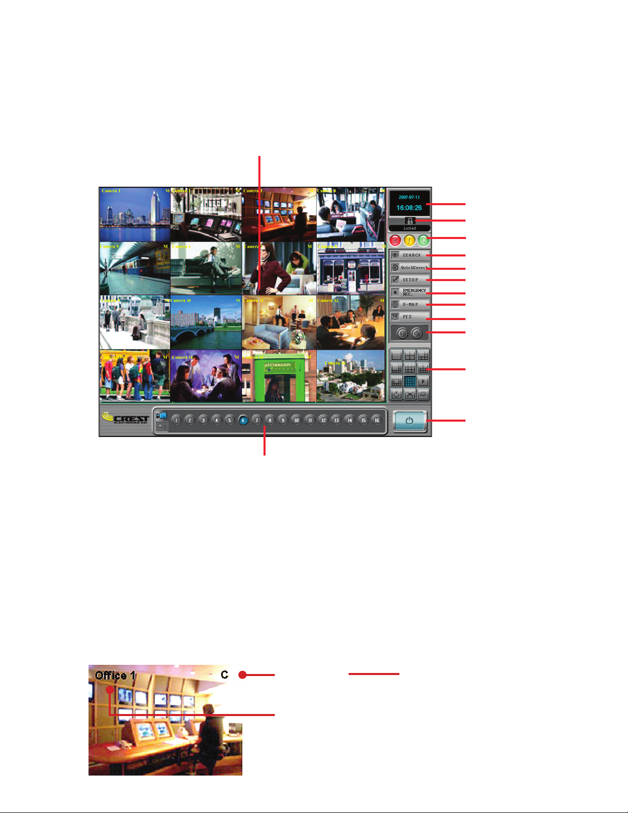
is section describes the main screen and its’ menu buttons. e image below details the name of the but-
tons.
Screen Di vision and Con trols
Current Date and Time
Search
Setup
Camera / Relay Selection
Emer gency record
PTZ con trol
E-Map
Quick Search
Audio on/off
Mute Alarm
System Exit
Image Display Area
Image Display Area
e image display area displays live images of the current cameras. is display can be changed by clicking
on the screen division buttons (see screen division section for the different views available). To change the
screen from multi camera view to single camera view, double click the le mouse button in the image you
want to bring up in single view, or click in the image making it the selected camera (will be highlighted in
red), then click the single camera di vision button. To change back, double click within the image. Each image
displays the camera name and the recording mode in use at the top of every image. e various modes are: C
System Setup).
Log in / log out
System Status
Recording Type
C : Continuous Recording
M : Motion Recording
S : Sensor Recording
E : Emergency Recording
Camera Name
Page 11
3
Current Date and Time
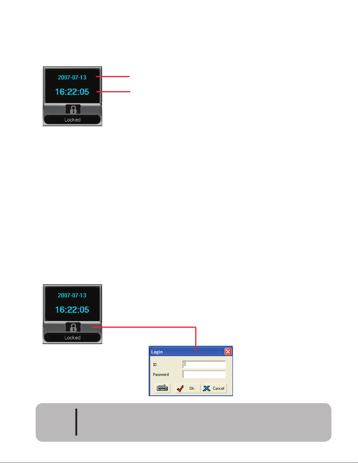
is displays the current date and time. e date is displayed in 24 hour format. e date is displayed in year/
month/day format by default. (See Chapter 2 System Setup to change the date format).
Date and Time Display
Current Date
Current Time
User Login
is button is used to login or logout a user. It also displays which user is currently logged into the sys-
tem. If no one is logged into the system, click the Lock icon to display the user login screen. If someone is
logged on, the lock will display the user’s name. Clicking the lock again will log the user off.
To login the first time, use the factory default username and password. e factory default user ID and
password are
system
/
manager. e maximum user id and password are limited to 7 characters.
Auto Logoff Function
If there is no activity for 10 minutes (fixed) the system will automatically logoff the current user. e user
will have to login to regain system functions. e user name will indicate “Locked” to show that the user
has been logged off the system.
Click the lock icon to display
the login popup.
Factory default user id and password are:
system / manager
Aer anAdmin user has been registered, user login by factory default will be disabled
and login can only be done by registered users. Factory default login can be reinstated
by deleting all registered users.
CAUTION
Page 12
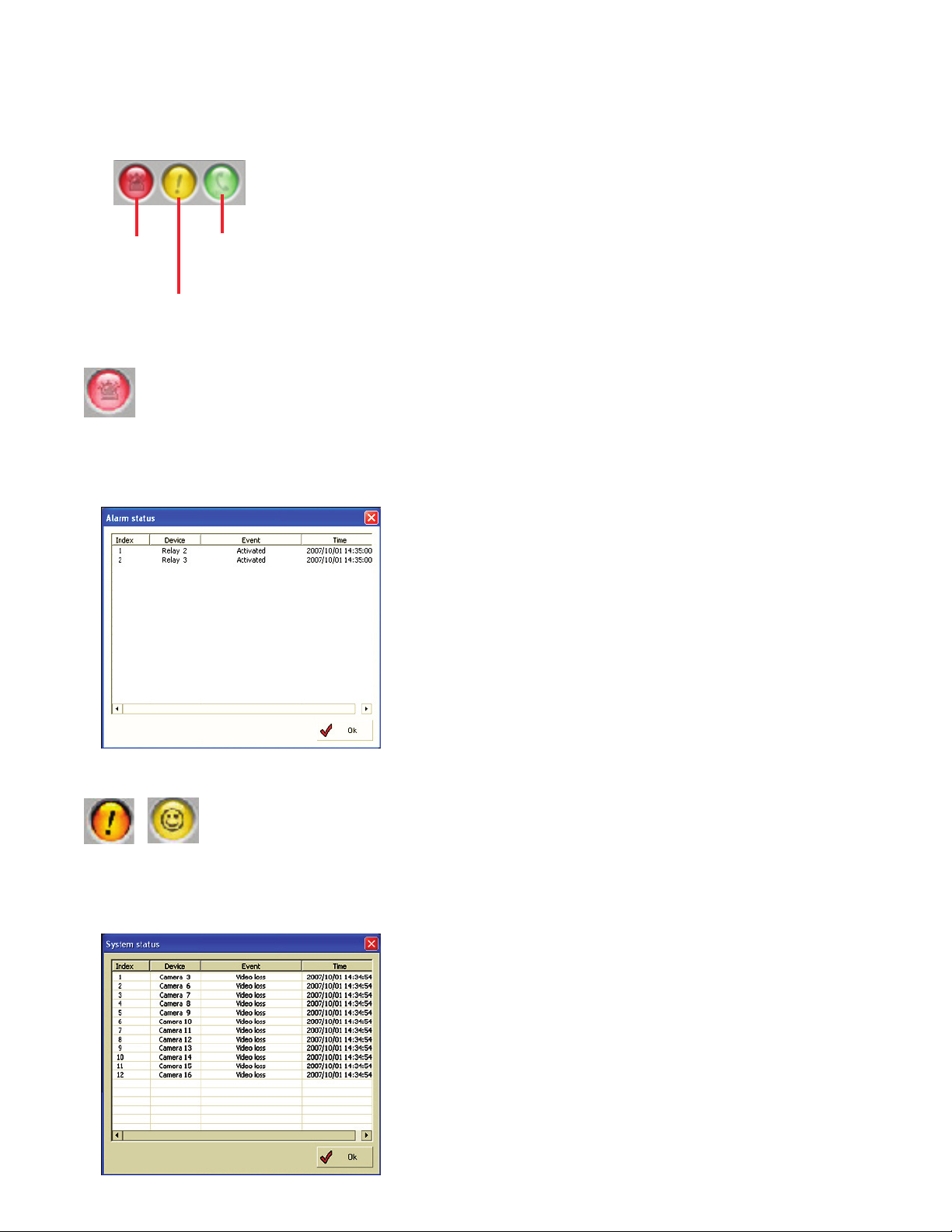
System Status
ere are three system status buttons. ese display information about active alarms/relays, system status
and network status.
Alarm/Relay
Status
Network
Status
System
Status
Alarm Status
Select the icon and alarm status window will open. Sensor alarm and relay on status will be shown. When the
alarm and/or relay is over, message will disappear. Icon will turn bright red indicating an alarm.
System Status
Select icon and system status window will open displaying the system error. e icon will display a smiley
face when in normal state and an exclamation mark when in an abnormal state.
Page 13
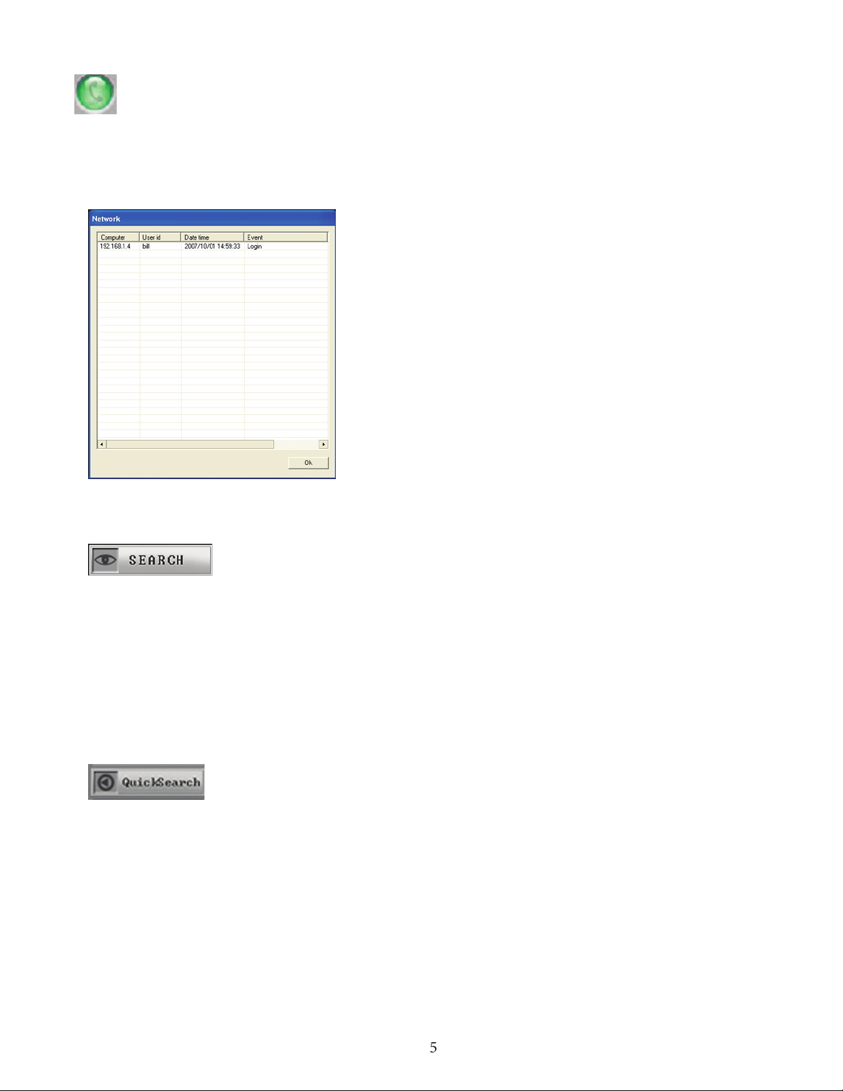
5
Network Status
Select the icon and the network status window will open. Window will show connected network client
information. e information will disappear when the network client has disconnected from the DVR.
Search Screen
e search screen is used to search previously recorded video. e search function is only allowed when
the user has been granted search function authority by the DVR administrator. e function will be re-
stricted when the user has not been granted search rights. Please refer to Chapter 3 Search Function for
search details. For details on setting up user rights, please refer to Chapter 2 System Setup.
Quick Search
Quick Search allows the user to review video from the selected camera without leaving the live screen.
Please refer to Chapter 3 Search Functions for details on Quick Search.
Page 14
6
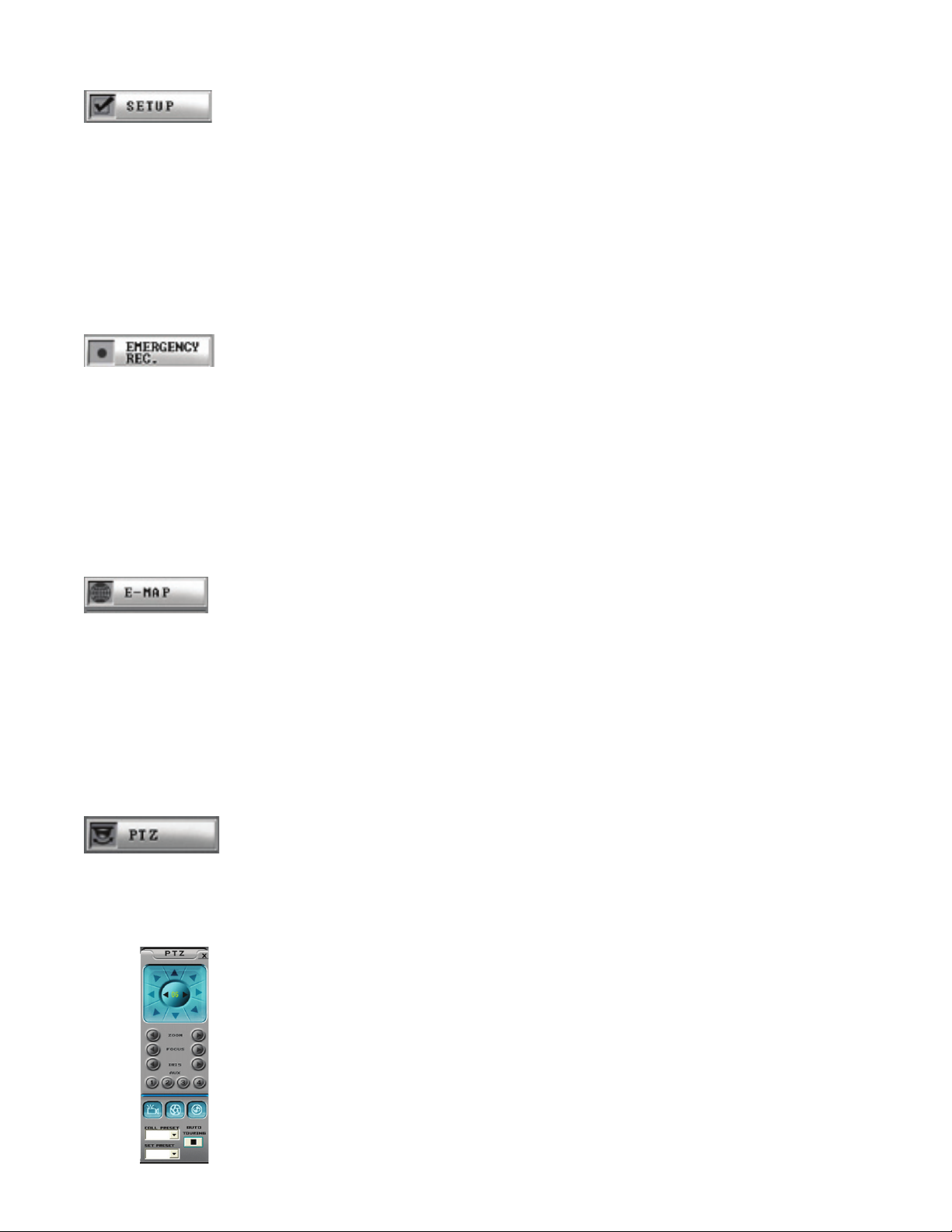
Setup Function
Click the setup icon and the setup windows appear. Here the user can do such things as set the recording
function for the cameras, set the recording frame rate, name the cameras, set the motion grid for a camera,
set up PTZ cameras, set the networking functions for the DVR, set the alarm functions just to name a few.
Please see chapter 2 System Setup for more details.
Emergency Record
e Emergency Record button provides an efficient way to record all channels in an emergency situation.
By clicking this button the system will record all channels until emergency record is turned off. To turn off
Emergency Record, click the Emergency Record button a second time. To use emergency record on a single
channel please read the section titled Main Screen Pop-up Menu later in this chapter.
E-Map Function
Provides an electronic map showing the location of cameras and sensors. e system provides several default
maps or a custom map can be designed and imported into the e-map function. For details on setting up and
using the E-Map Function please refer to Chapter 5 E-Map Function.
PTZ Controller
Click the PTZ button to open the PTZ controller. With the PTZ controller the user can control the PTZ cam-
era. Please refer to Chapter 2 System Setup - PTZ Setup for details on setting up the PTZ camera..
Page 15
7
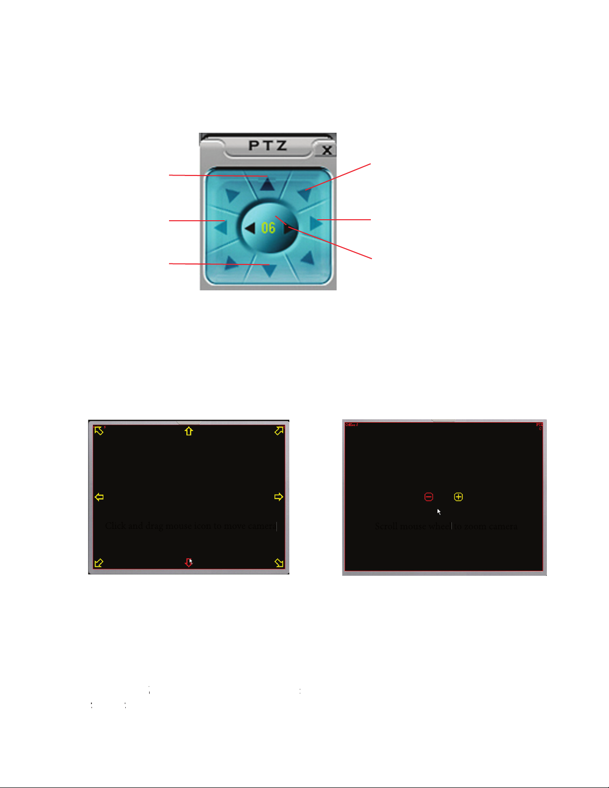
In order to control the PTZ camera the PTZ controller must be on screen. To activate the PTZ controller
click the PTZ button on the main DVR screen. Click anywhere in the PTZ camera’s image, this will select the
PTZ camera as the active image. e PTZ controller will display the number of the selected camera. See im-
age below.
Move PTZ up
Move PTZ
le
Move PTZ
down
Move PTZ
right
Move PTZ diagonally
Selected camera
e system also allows the user to control the PTZ camera with the mouse. To use the mouse controls double
click the live image of the PTZ camera so the only camera showing is the PTZ camera. Click the PTZ button
to bring up the PTZ controller. Click the le mouse button and hold it down, the control arrows appear (see
image below). Click and drag the controller in the direction you wish to move the PTZ camera. Release the
mouse button to stop the camera. To zoom in and out use the mouse scroll wheel. Scroll the wheel forward to
zoom in, backward to zoom out. On screen guides will appear as a guide (see image below).
Click and drag mouse icon to move camera
Scroll mouse wheel
to zoom camera
Setting Presets
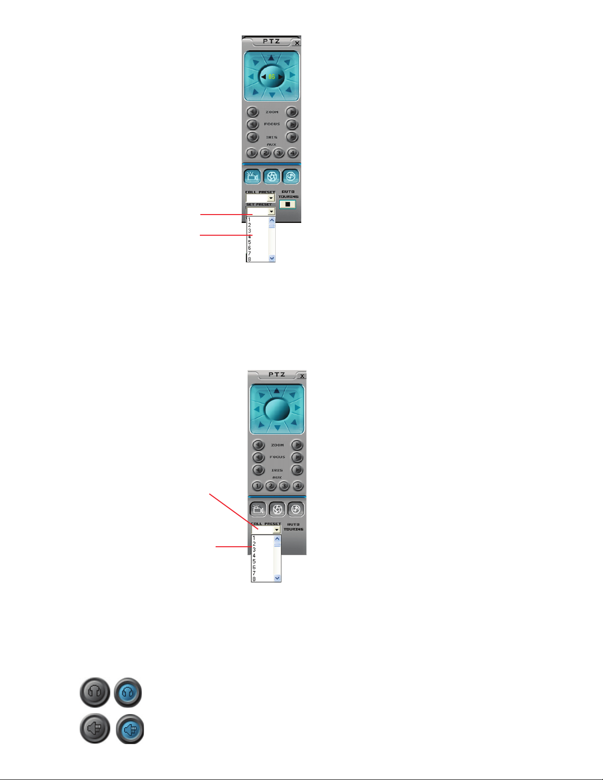
e 7000 series allows up to 64 presets. (See PTZ camera documentation for number allowed by camera). To
set a preset move the camera to the desired location, click the down arrow button on the “Set Preset box. Se-
lect the preset number you wish to associate this camera location with. e image below displays the set pre-
set box.
any PTZ camera manufacturer
s program their cameras using 0 as the beginning
preset
number
. Other
s, suc
h as Pelco
preset numbering with 1
. e CDVS
-7000 preset number 1 relates to
PTZ camera that uses Pelco P or D
protocol.
hich will renumber based on the Pelco protocol,
Page 16
8
Audio and Alarm Indicator
Use these buttons to listen to live audio and audible alarm. Please see Chapter 3 Audio Setting for setting up
audio and Chapter 2 Alarm Event Sound Effect for setting up audible alarm.
Click Button to hear selected channel live audio. Blue indicates that audio is on.
Click again to turn off.
Click Button to hear audible alarm. Blue indicates that audible alarm is on.
Click again to turn off.
Calling a Preset
To move the PTZ camera to a preset, click the down arrow button in the call preset window. Click the
number of the preset you set the camera to and the camera moves to the location set. Image below displays
the call preset function.
Select a number for the
preset location
Call Preset window
Click the set preset button
Select number for preset
Page 17
9
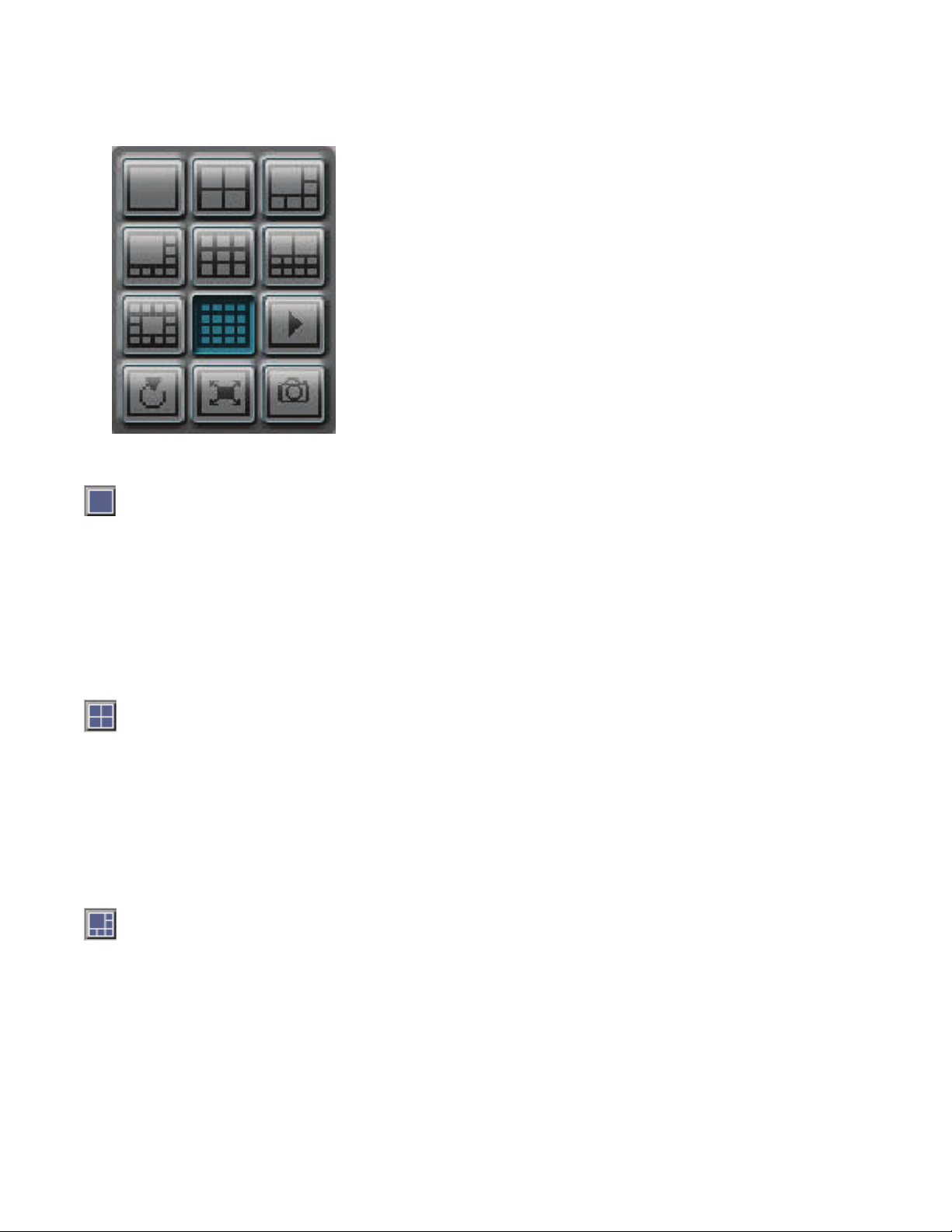
e different screen modes are as follows 1, 4, 6, 8, 9, 10, 13, 16.
All screen divisions will allow for sequencing through all 16
cameras. See chapter 2 Setup Function for details on setting the
sequencing dwell time.
Single Camera Display Button
is will allow the user to view only one camera at a time. To view a single camera, le click highlighting the
desired camera in a red outline. Next, le click the single camera display button. e selected camera will re-
place the current view with a single camera view. To have the system rotate from one camera to another, click
the Next button. To have the system automatically change from one camera to another, click the Auto Rotate
button
(see below).
Four Camera Display Button
is will allow the user to view four cameras at a time. e system displays the cameras in the following
configurations: cameras 1,2,3,4, cameras 5,6,7,8, cameras 9,10,11,12, cameras 13,14,15,16. To have the system
rotate from one 4 camera view to another, click the Next button. To have the system au to matically change
from one 4 camera view to another, click the Auto Rotate button (see below).
Six Camera Display Button
is will allow the user to display six cameras at a time. e different configurations are: cameras 1 - 6, 7 - 12,
and 11 - 16. To view, click on one of the cameras you want to view and click the 6 cam era display button. To
have the system rotate from one 6 camera view to another, click the Next button. To have the system auto-
matically change from one 6 camera view to another, click the Auto Rotate button (see below).
Page 18

Nine Camera Display Button
is will allow the user to display nine cameras at a time. e different configurations are: cameras 1 - 9, and
8 - 16. To view, click on one of the cameras you want to view and click the 9 camera dis play button. To have
the system rotate from one 9 camera view to another, click the Next button. To have the system automatically
change from one 9 camera view to another, click the Auto Rotate button (see below).
Ten Camera Display Button
is will allow the user to display ten cameras at a time. e different configurations are: cameras 1 - 10, and
7 - 16. To view, click on one of the cameras you want to view and click the 10 camera dis play button. To have
the system rotate from one 10 camera view to another, click the Next button. To have the system automati-
cally change from one 10 camera view to another, click the Auto Rotate button (see below).
irteen Camera Display Button
is will allow the user to display thirteen cameras at a time. e different configurations are: cameras 1 - 13,
and 4 - 16. To view, click on one of the cameras you want to view, and click the 13 camera dis play button. To
have the system rotate from one 13 camera view to another, click the Next button. To have the system auto-
matically change from one 13 camera view to another, click the Auto Rotate button(see below).
Sixteen Camera Display Button
is will allow the user to display 16 cameras at a time. On the 32 channel system, click the Next button to
sequence to cameras 17-32.
Display Next Screen Button
If you are in any other screen display mode other than 16 camera display, use this button to go to the next
display configuration. By repeatedly clicking this button you will rotate through all the available display
screens for the currently selected screen division.
Screen Sequencing (Auto Rotation)
is button is used to have the
surveillance screen rotate in order according to the sequencing interval value
set on the environment setting.
Page 19
Full Screen Mode
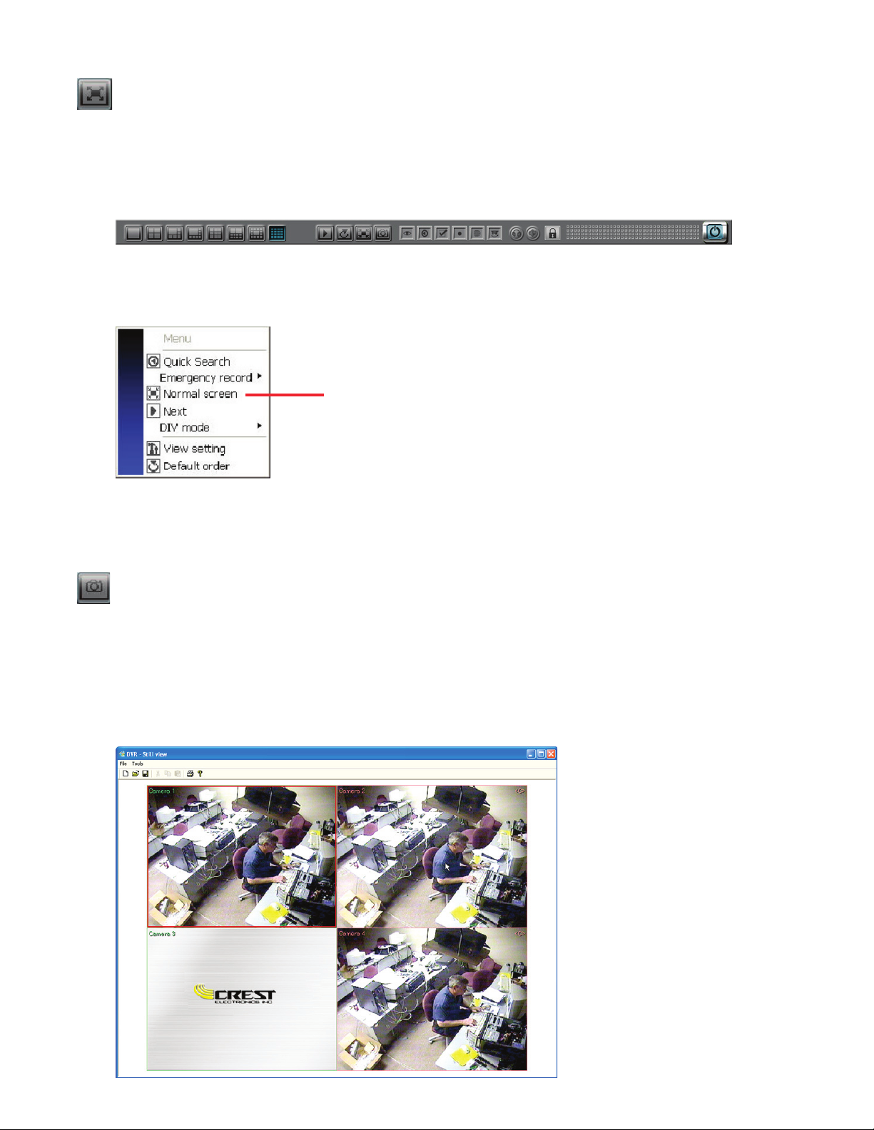
Click this button to change the display to full screen. Use this mode to minimize the screen’s GUI menu to
the bottom of the screen. Click the right mouse button to display Main Screen pop-up menu and click Nor-
mal Screen to change back to the original screen. (See Image below).
Click Normal to change screen back to default
screen with GUI.
Snapshot
is function allows the user to capture a snapshot of the live screen. Click this button to take a snapshot of
the current live screen. Aer clicking, the snapshot window will come up as shown below. Snapshot allows
you to flip or mirror the image, and
manipulate the contrast and brightness
Printing requires that you have a printer connected and set up on the DVR.
GUI Minimized when in full screen mode
Page 20
Snapshot File Menu
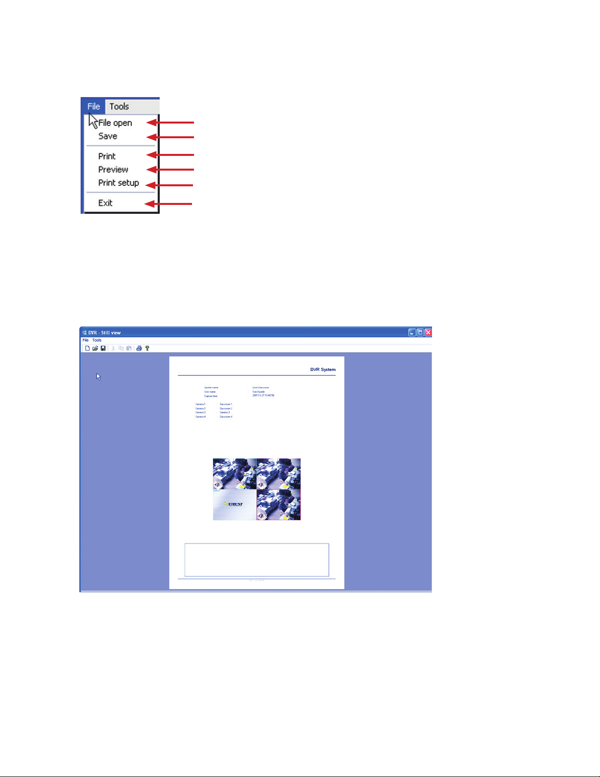
is menu controls the opening, saving and printing functions for the snapshot image.
Open
image file saved as snapshot. (JPG, BMP)
Save snapshot as image file (JPG, BMP)
Print Snapshot screen.
Preview snapshot printed image before printing.
Open Print setup window.
Exit Snapshot window.
Print Preview
Previews what the printed snapshot will look like. Displays the system name, user name, capture time and
camera name.
Page 21
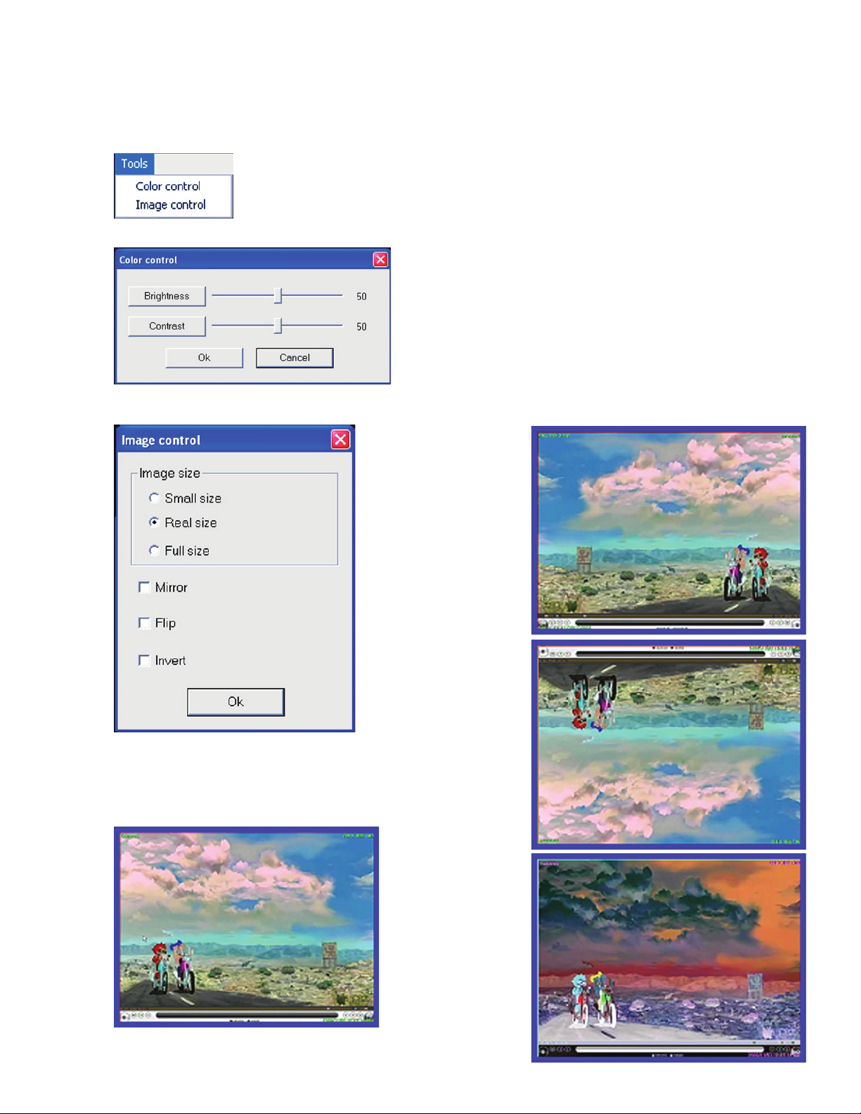
Snapshot Tool Popup Menu
Allows the user to adjust the snapshot image. Adjustments are brightness, contrast, image size, mirror, flip
and invert.
Color control window
Image
control window
Original Snapshot Image
Brightness - Adjust the image’s brightness
Contrast - Adjust the image’s contrast
Image size (3 levels -
Small, Original and Full)
Original image mirrored
Original image
flipped
Original image
nverted
Page 22
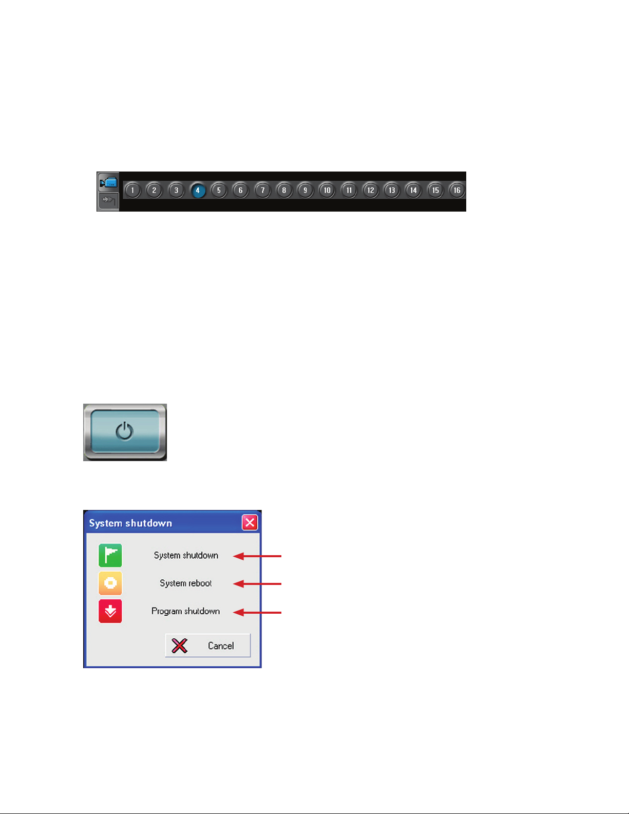
is function allows the user to select a specific camera. e selected camera is highlighted in blue. When
the screen is in a screen division that does not display all cameras, selecting a camera will bring up the screen
division that contains that camera.
Use buttons to select camera for surveillance.
Press relay icon to view relay status and control relays
Use the system shutdown button when you want to shutdown the DVR, reboot the DVR or exit the DVR
program and go into the Crest System Desktop. Click the system shutdown button to bring up the system
shutdown pop up menu. Choose the option you want to perform that action. If the user log in appears then
you must log in with a user that has sufficient rights to power down the system.
System shutdown
Power off the system
Reboot the system
Shut down DVR recording and go into the Crest Desktop
Page 23
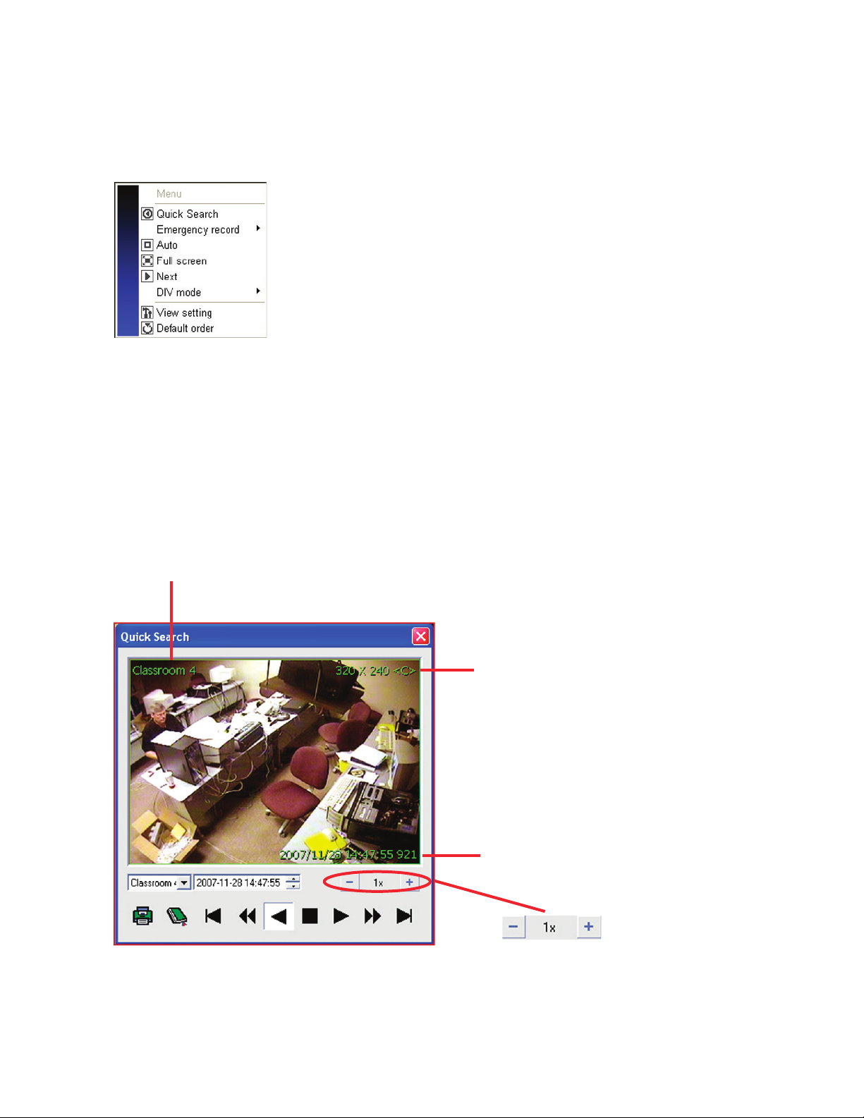
Main Screen Pop up Menu
e main screen pop up menu can be used instead of using the menu controls on the right side of the main
screen. is is particularly useful when the main screen is in full screen mode and the GUI is hidden. e
following are descriptions of the various functions available from the pop up menu.
Quick Search
e Quick Search function allows the user to review recorded video from one camera. Select the camera you
want to review using the camera buttons at the bottom of the screen or just click the live image of the camera
you want to review. e camera will be highlighted indicating that it is the selected camera. Right click in the
image area to bring up the pop up menu and click the “Quick Search” icon. e quick search window will be
displayed.
Resolution size / recording mode used to record image.
Date and time of recorded image.
Camera name.
Click + to speed play.
Click - to slow play.
Page 24
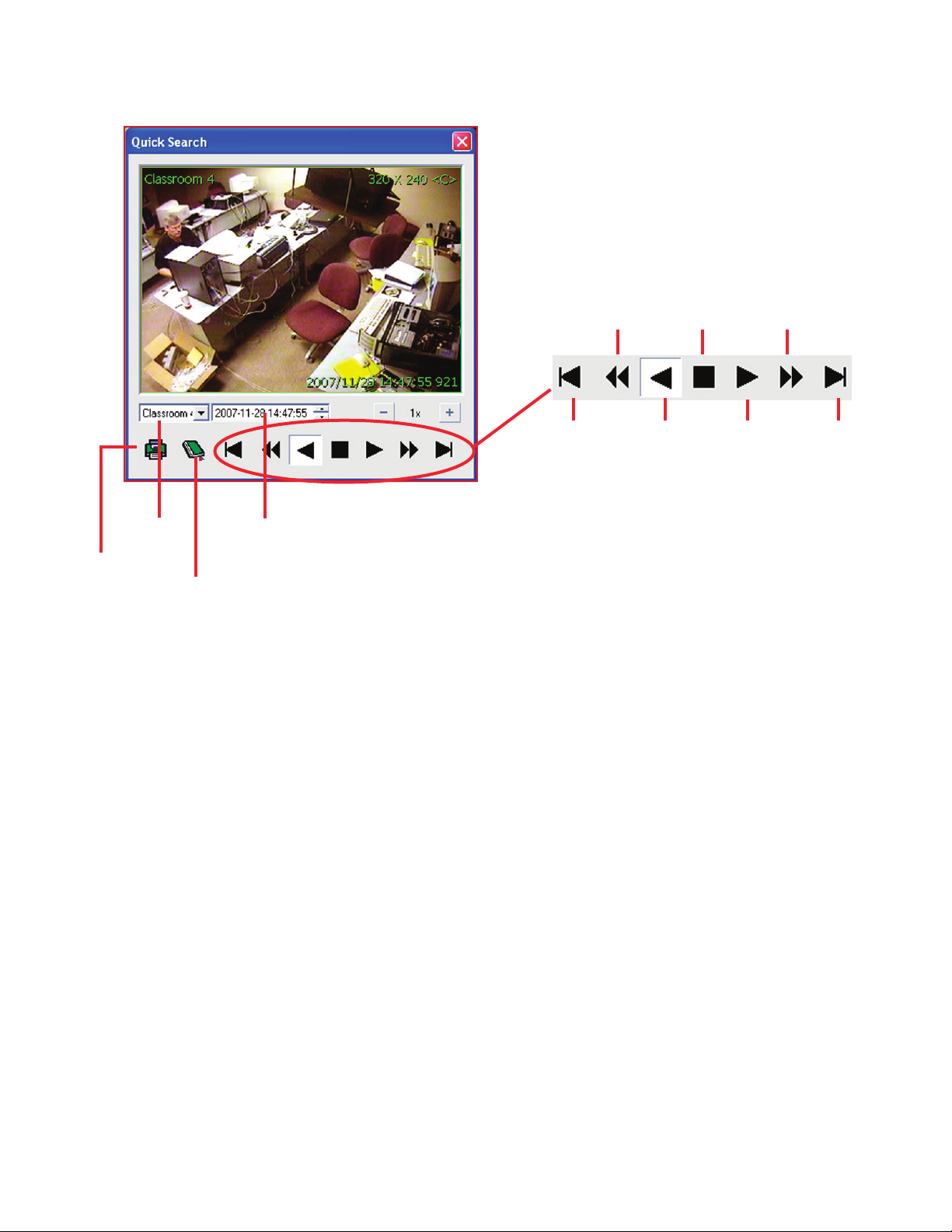
ack 1 frame
Fast reverse
R
everse play
Pause
Forward play
Fast forward
Forward
1 frame
Select camera
Select date and time
Bookmark
func
tion
Print function
Quick Search cont.
Emergency Record
e emergency record function of the main screen pop up menu allows for the image recording during an
emergency. ere are two modes of emergency recording. Emergency recording of all channels and emergen-
cy recording of just the selected channel. Emergency recording will override all other recording modes. Aer
emergency recording has been enabled the image will display <E> for the recording type. It will continue to
record in emergency mode until it is turned off by the user.
Auto
e auto function turns on /off auto sequencing. If the live screen is in any division mode the DVR will
sequence automatically through all the screens of the selected division. For example if the screen is in one
camera division then when turning on auto sequencing the DVR will automatically rotate through cameras
Full Screen / Normal Screen
is function allows the user to change the main screen to “Full Screen” mode moving the GUI to the bot-
tom of the screen. When the screen is in “Full Screen” mode menu item will change to read “Normal Screen”
allowing the user to change the screen mode back to normal mode.
Page 25
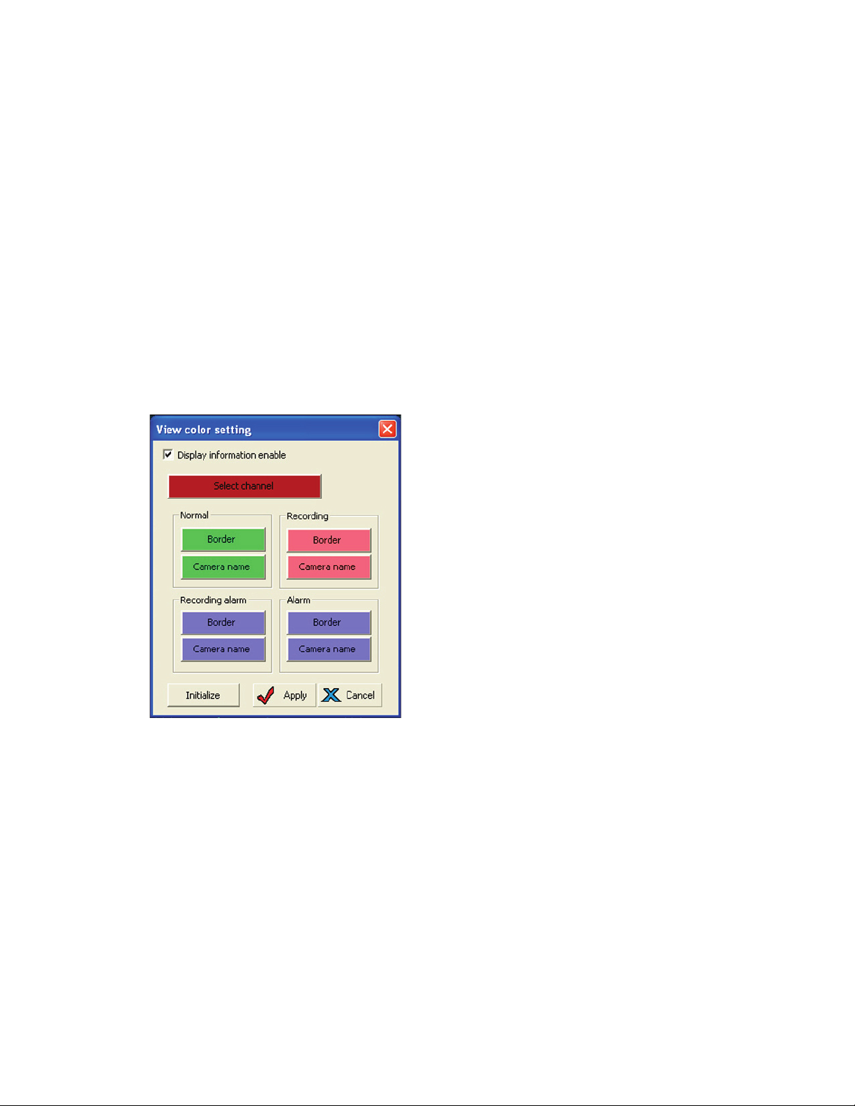
View Settings
Allows the user to change the default colors used by the system for image border and camera name.
• Normal : Color settings indicating normal status.
• Recording : Color settings indicating recording status.
• Recording alarm : Color settings indicating alarm status while recording.
• Alarm : Color setting during sensor alarm activation.
“Next” Screen
Click this to move to the next screen when in division screen mode.
DIV Mode
Allows the user to choose the preferred screen division. Varies based on the number of channels the DVR
has.
Default Order
e DVR allows the user to move the cameras from their original screen position by clicking on an image
and dragging it to a new screen location. e image will then stay in that new position until the DVR pro-
gram is shut down or rebooted. e Default Order function allows the user to change the image screen order
back to the system default without rebooting the system.
Page 26

Page 27
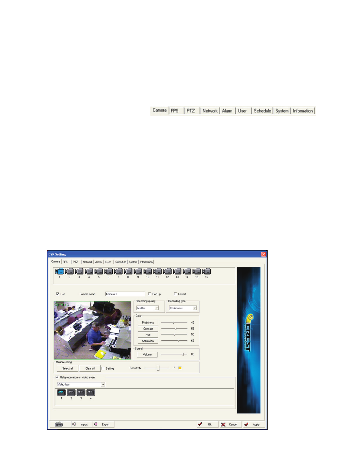
Chapter 2 details various options for setting up the Crest 7000 series DVR. e setup function consists of 9
different setup menus. e different menu tabs are shown below. is chapter will explore each of the differ-
ent menus and explain the various options available with each.
e available setup menus are:
e camera settings menu allows the user to set the various settings for each camera. is menu also sets the
motion grid and sensitivity per camera for motion recording. e image below is the camera settings win-
dow.
9 different setup menu tabs
Page 28
20
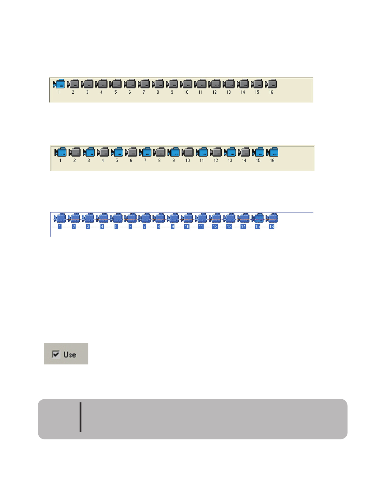
Camera Selection
e camera selection bar is used to select the camera or cameras that settings are to be changed. To select a
single camera just click the selected camera icon. e icon will change from gray to blue indicating that it has
been selected for changes.
To select multiple cameras for changing, hold down the control (Ctrl) key when clicking the camera icons.
To select all cameras click and hold down the le mouse button while dragging on top of the camera icons.
Select Camera for Use
is sets whether the camera port is turned on or off in the system. If this box is le unchecked the system
will turn off the camera port. e system will ignore any input from this channel even if there is a camera
connected.
If this box is checked the system will try and detect a camera signal even if there is no camera connected. e
system will give a video loss alarm if this box is checked and there is no camera connected to the port. To
prevent unwanted alarms camera ports with no cameras connected should be unchecked.
Warning
Disabling a camera port will reset the FPS for that camera to the lowest frame rate.
Please check frame rate when using camera port again
Page 29
Camera Name
Enter a name to identify the selected camera. e camera name can be up to 32 characters long.
Camera Pop Up
Check this check box to have the system pop up the selected camera when motion or a sensor alarm is de-
tected. e length of time the pop up is displayed can be set in the system. Please see section on System Tab
“use pop up release time”.
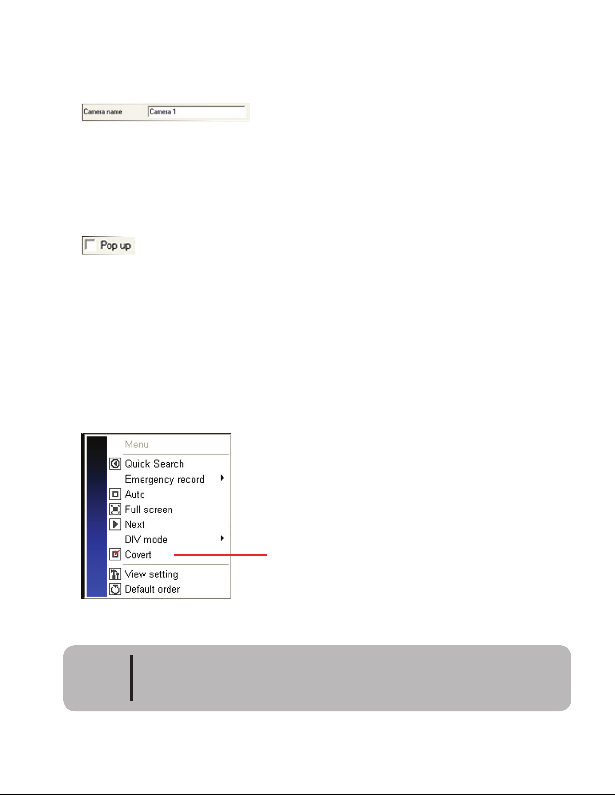
Covert
When covert is checked the camera image will be hidden on the live, playback and remote view screens. e
system will continue to record the camera but the selected camera will not be displayed. To view a covert
camera the user must be an administrator and log on to the DVR. e live screen will not display the image
until the administrator uses the live screen pop up menu and selects covert. If the user does not have ad-
ministrator rights the covert option will not display on the pop up menu of the live screen (Please see image
below). When the administrator logs out of the system the covert camera will revert to hidden or the admin-
istrator can click covert in the pop up menu. e hidden camera cannot be displayed at anytime while in
playback at the DVR. In order to see playback the covert check box must be unchecked.
Please be aware that if you give a user rights to backup recorded video they will be not
able to backup the covert camera. Only administrators can backup hidden cameras.
Caution
Selected camera is in covert mode
Click to view camera.
Page 30
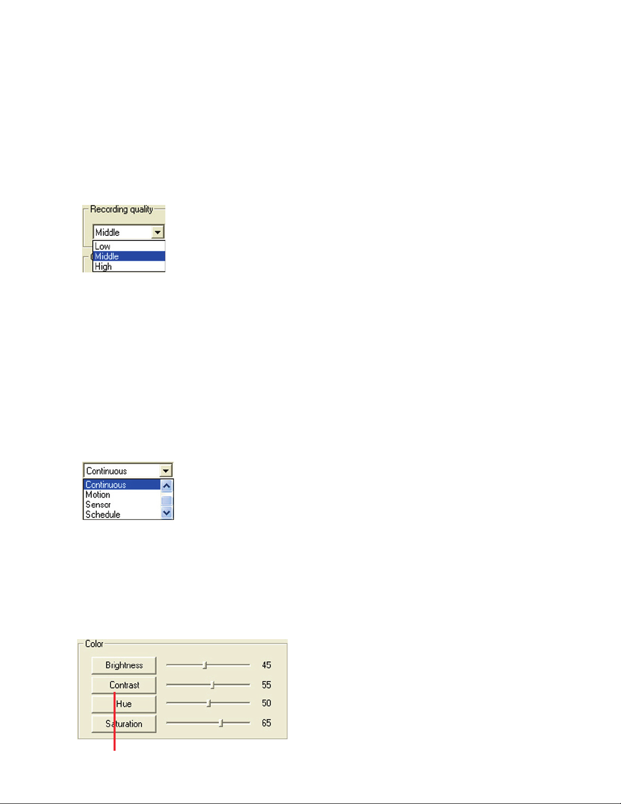
Image Quality
Image quality setting is used to control the amount of compression the system uses to store video. ere are
three settings:
1) High: Highest image quality with very little compression, the file size is very large.
2) Middle: Middle picture quality with normal compression and normal file size.
3) Low: Very low picture quality but very high compression with small file size.
e factory default is Middle and it is recommended that this setting be used.
Recording Type
is function sets the mode of how the camera will record video. ere are 5 different modes.
1) No Recording: e system does not record video for the selected camera.
2) Continuous: e system records the selected camera 24hrs continuously.
3) Motion: e system records the selected camera only when it detects motion.
4) Sensor: e system records the selected camera only when there is a sensor alarm.
5) Schedule: e system records each camera following the recording schedule set for it in the
Schedule tab.
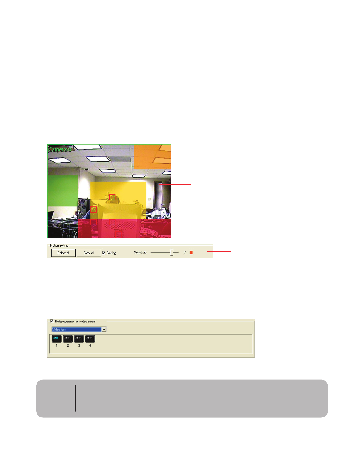
Color
is function allows the selected camera to be adjusted for brightness, contrast, hue and saturation. Changes
made to the camera image are recorded. Pressing the name of each adjustment will return the value to the
system default.
Click these buttons to return to default values.
Page 31
23
Motion Area Selection
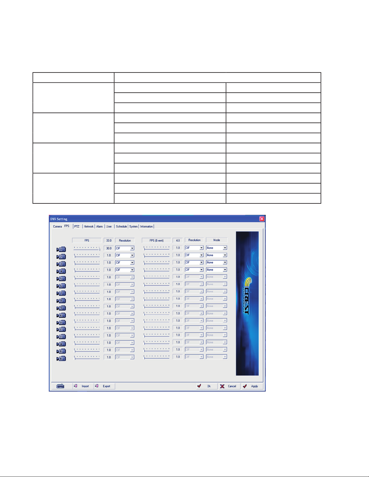
Click the setting check box to all motion areas for the selected camera. To set the area that the system moni-
tors for motion detection, click and drag to select area. e Select All button can also be used to select the
entire area of an image for motion detection. Clear All will clear the entire image area, if no area is selected
the DVR will not record.
To set the sensitivity, drag the slider le (less sensitive) or right (more sensitive). e area selected will have
different colors based on the sensitivity setting used. Red is more sensitive and green is less sensitive. Mov-
ing the slider bar all the way to the le is no sensitivity. e sensitivity setting must be set before clicking and
dragging on the image. Multiple areas with different sensitivity can be set in the image area. Red squares will
appear indicating motion in a selected area. is is useful when trying different sensitivities to eliminate false
motion.
Image area showing different motion areas with
different sensitivity settings. Square boxes indicate
motion in that area.
Use motion setting bar to view selected
motion areas. Select entire image, clear
entire image, and set sensitivity.
Relay Operation On Motion Event
Use this function to activate a relay contact when the system detects motion or a signal loss. Multiple relays
can be set for each camera.
Relay will not operate when Relay Activate mode is set to schedule. Schedule mode
overrides all other modes. Please refer to Alarm Tab later in this chapter.
Caution
Page 32
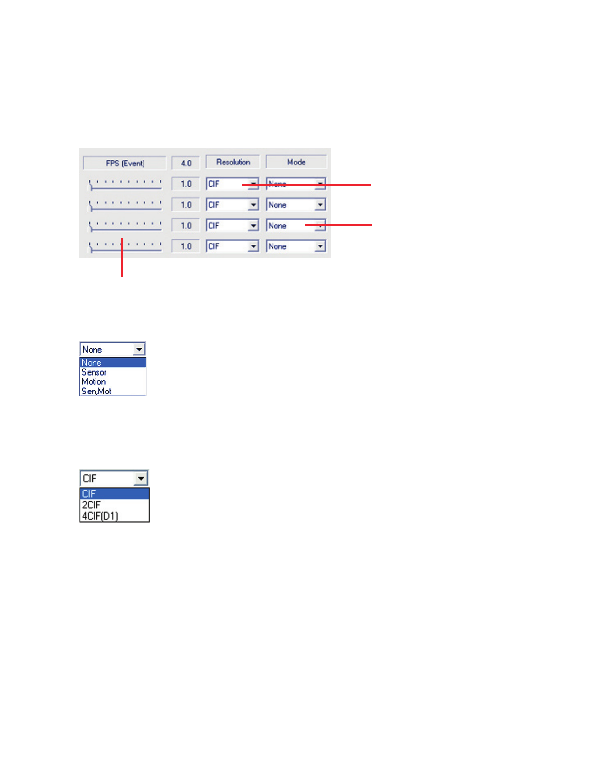
is tab is used to set the frames per second used when recording video. e following chart shows the maxi-
mum frame rate available based on the resolution setting.
Model
Max Frames for each resolution
CDVS-7516
CIF (Low) 360 X 240
480 fps
2CIF (Middle) 720 X 240
240 fps
4 CIF (High) 720 X 480
CDVS-7316
CIF (Low) 320 X 240
2CIF (Middle) 640 X 240
60 fps (3.0 max per camera)
VGA (High) 640 X 480
30 fps (1.0 max per camera)
CDVS-7308
CIF (Low) 320 X 240
2CIF (Middle) 640 X 240
60 fps 7.5 max per camera)
VGA (High) 640 X 480
30 fps (3.0 max per camera)
CDVS-7304
CIF (Low) 360 X 240
2CIF (Middle) 720 X 240
60 fps (15 max per camera)
VGA (High) 720 X 480
30 fps (7.5 max per camera)
Adjusting FPS
Move the frames per second slider bar to the le or right to change the frames per second. e total FPS used
will display at the top of the FPS column. Please note that with the 7300 series you will only be able to use a
total of 48 FPS when in 2 cif mode and a total of 16 fps in 4 cif when using all 16 cameras. is is because of
the algorithm, it is not able to distribute the remaining frames.
Page 33
25
Intensive Recording
Intensive recording is to be used when recording is done with low picture quality, such as recording in CIF.
Aer the motion or sensor event is detected the intensive recording will take place with the preset settings.
Please be aware that intensive recording cannot be used to gain more frame rate than the system is capable of
producing. For example if you are recording all cameras on a CDVS-7316 in VGA mode (4 CIF) you will still
only be able to get 1 fps.
Select Resolution
Select Mode
Select Frame Rate
Modes used for intensive recording
Resolutions used for intensive recording
Page 34
26
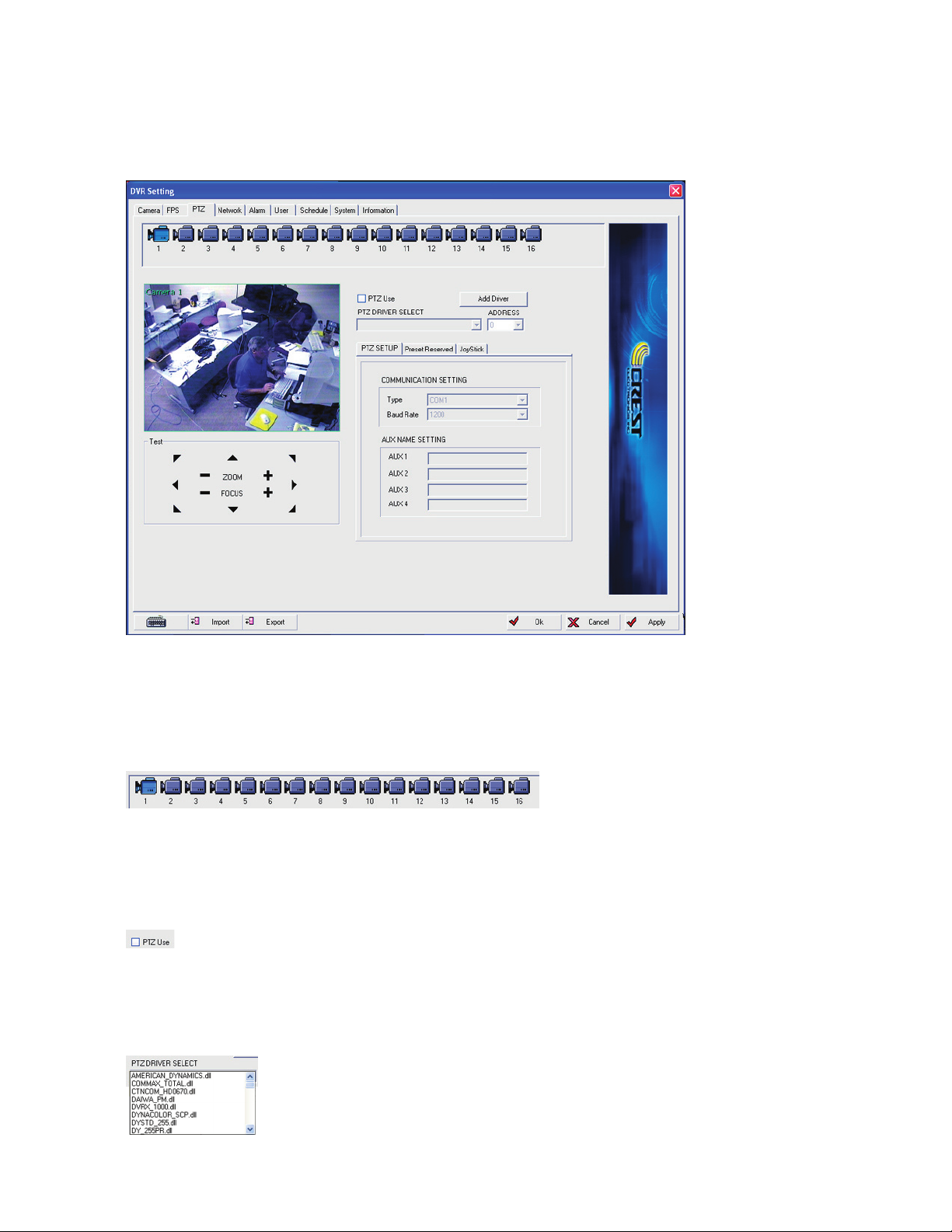
e PTZ Tab is used to setup any PTZ cameras that may be on your system. is is also used to set preset
tours as well as set the joystick to control the dvr.
Camera Selection
Used to select the PTZ camera that will be set up.
PTZ Use
Choose if camera is a PTZ camera.
PTZ Driver Protocol
Select the proper PTZ protocol for the selected camera.
Page 35
27
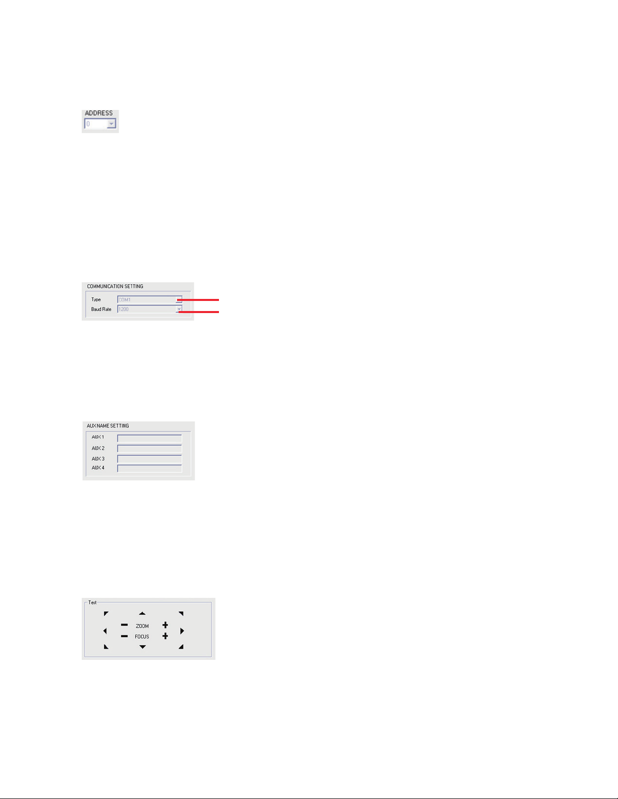
PTZ Address
Enter the PTZ camera’s address in this box. e address is set at the camera and then entered here. Failure to
set proper address could result in PTZ camera malfunction.
PTZ Communication Setting
Use to set PTZ communication type. RS-485 and RS-232 are both supported. Set baud rate. Please note the
communication type and baud rate are determined by the PTZ camera settings. Please check these settings
on the camera before setting in DVR. Failure to use the proper settings will result in a malfunction of the
PTZ camera.
Set proper communication type 485 or RS-232 (Comm 1 or Comm 2)
Set proper baud rate
Aux Name Settings
Input the name for the contact control device on AUX terminal. Aux terminal supports a maximum of 4
devices. e number differs according to the device.
PTZ Test
Used to test if the DVR can conrol the PTZ. If the DVR cannot control the PTZ camera recheck the settings
to be sure they match that of the PTZ Camera. Also check to see if the RS-485 or the RS-232 connections are
correct. Please see the connections later in this chapter.
Page 36
28
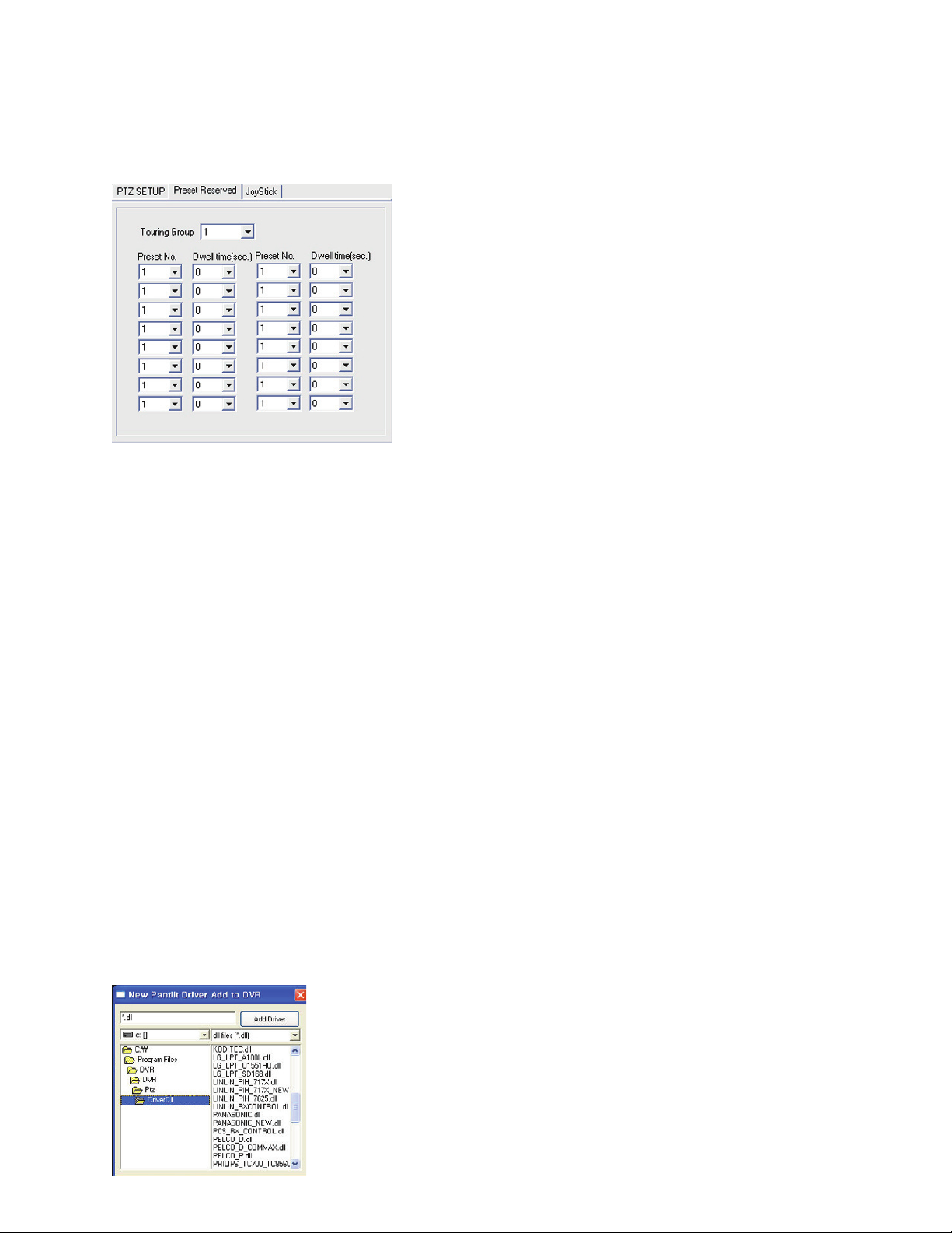
Preset Tour Setup
e DVR has the ability to sequence through a series of presets set in the PTZ camera. Use the preset reserve
tab to set the presets to be used. For information on setting the camera preset please see chapter 1 Setting
Presets.
To set up a preset tour follow the following steps:
1) Select the touring group.
e system has four touring groups with each group supporting 16 presets. For a total of 64 presets.
2). Select the camera preset number.
e system has 16 preset and each preset supports up to 64 camera presets.
3). Select the dwell time.
Set the dwell time to 0 if you want the DVR to skip the preset otherwise set the dwell time between
3 - 60 seconds. e minimum dwell time is 3 seconds maximum is 60 seconds.
Joystick Setting
Not supported at this time.
Add PTZ Driver
e system allows for the addition of new PTZ drivers. Use this button to add a new driver. Only drivers pro-
vided by the manufacturer should be added to the system. Please be careful not to delete any of the protocols
as this may lead to a malfunction with existing PTZ cameras.
Navigate to the directory that contains
the driver you want to add; highlight the
driver and click Add Driver button
Page 37
29
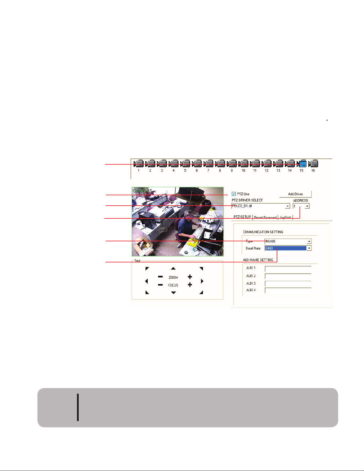
PTZ Setup Example
e figure below shows the PTZ setup Screen for Camera number 15 using a Pelco PTZ camera with the fol-
lowing settings:
• Pelco D protocol
• address 1
• RS-485 communication
• 2400 baud rate
Please Note: If any one of these settings are not correct your PTZ camera will not work.
Please consult the
manual that came with your ca
mera for instructions on setting up the camera.
If aer reading the manual
you are still unsure of the settings, please check with the manufacturer befor
e calling technical suppor
.
Camera # 15 selected
Turn on PTZ function
for camera 15
Select
Pelco D protocol
C
omm type 485
Baud rate 2400
Address set to 1
Aer entering your camera’s settings click the Apply button to save the settings. Click the OK button to exit
the PTZ controller and the Setup screen. Press cancel to exit without saving the changes made to the screen.
Please make sure to set the proper communication type when setting up the PTZ
dome. Unless specified at time of ordering all CDVS units will not come with a
RS-232 port.
Caution
Page 38
30
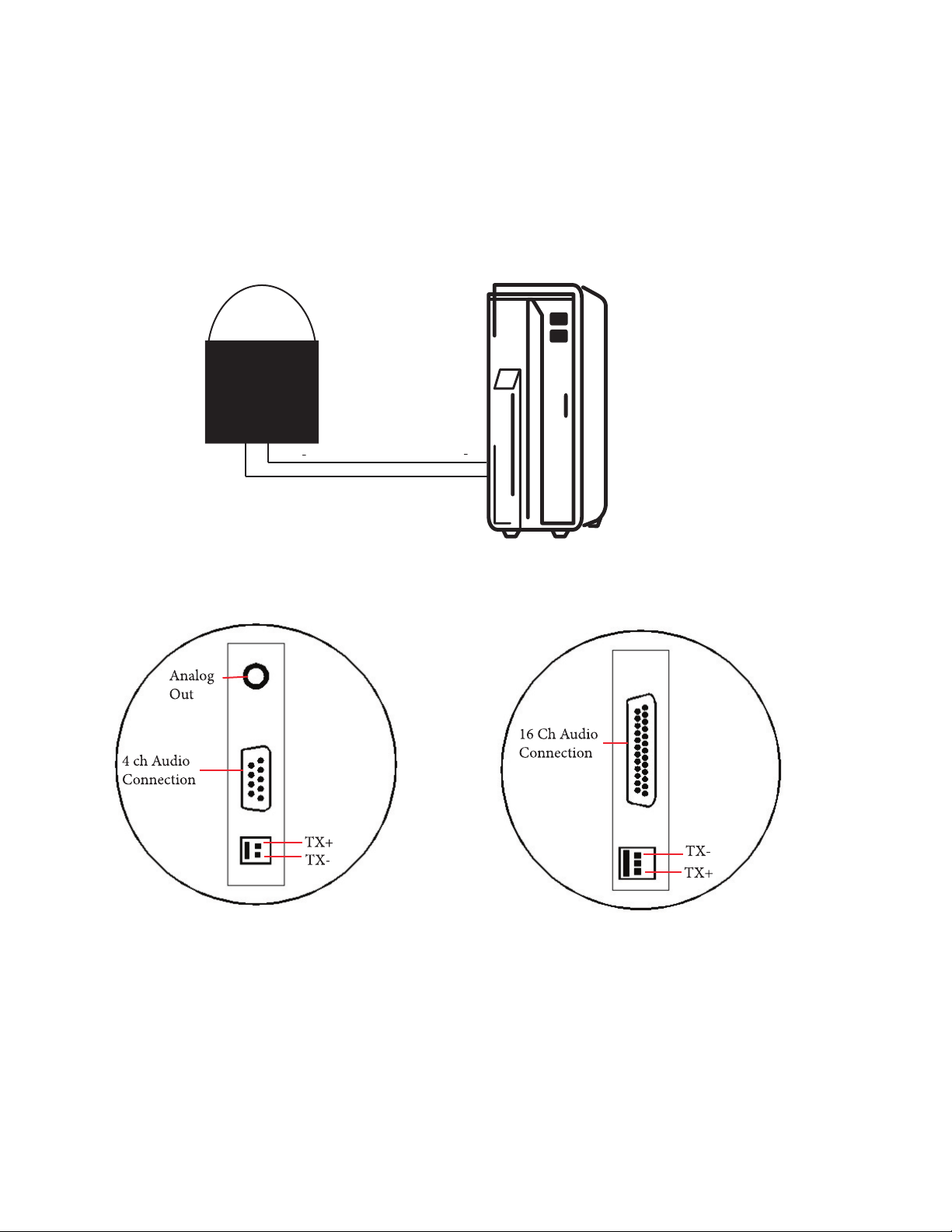
PTZ connection
Most PTZ cameras use a 485 or 422 connection to connect to a DVR. Some, however, require a RS-232 con-
nection. To connect a PTZ using 485 or 422 use the supplied cable. Connect the TX+ cable of the DVR with
the RX+ cable of the PTZ camera and the TX- cable of the DVR to the RX- cable of the PTZ camera. See
example below.
RX+
RX
PTZ Camera
7000 Series DVR
Connecting PTZ Using RS-232 Device
e CDVS-7000 series must be special ordered to include a serial port. e standard CDVS-7000 series DVR
does not include a serial port.
If the PTZ requires a RS-232 connection use the RS-232 cable supplied by the PTZ camera manufacturer to
the RS-232 (9 pin serial connection) port on the DVR.
TX
4 ch Audio
Connection
A
nalog
Out
Connection
7300 Exploded View of PTZ connection
7500 Exploded View of PTZ connection
Page 39
31
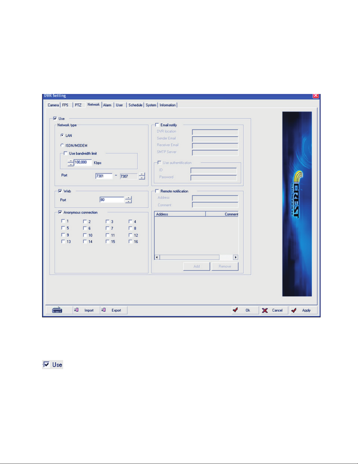
Network Settings
Click the network tab to enter the network setup page. is page allows the user to set up the DVR for re-
mote connection. is page only controls the DVR program, it will not set up the network communications
for the operating system. is must be done on the Crest System Desktop. Please refer to Chapter 3TCP/IP
for setting up the network connections.
Place a check mark in this box to enable remote connections.
Page 40
32
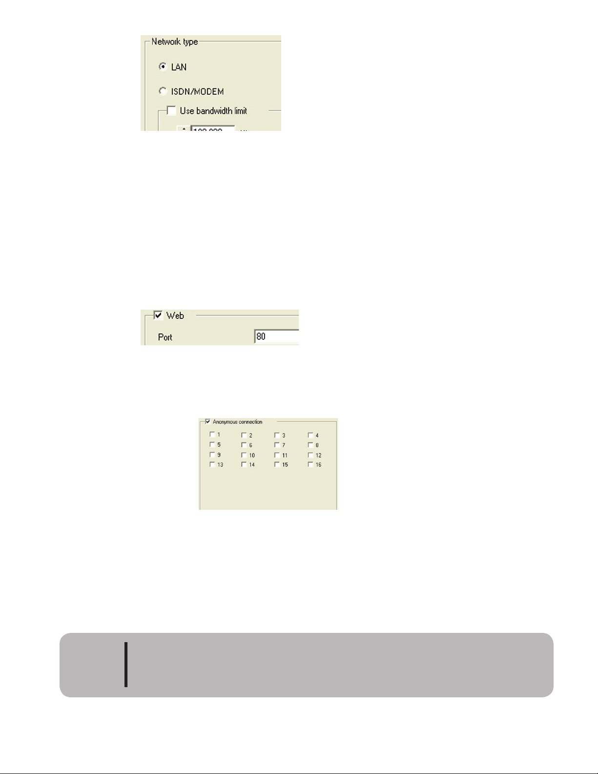
Network Type
e user to identify the type of network connection the system is using. e available
options are LAN or ISDN/Modem.
e DVR can limit the bandwidth it sends to the network. Check limit bandwidth and set the desired band-
width in kbs.
e user must also notify the system what ports the DVR system will be using to communicate with. e
default ports are 7301-7307. To change the program ports, just type in the first port number and the system
will automatically select the rest of the ports based on the first port number.
Check the Web check box if the user will be doing remote monitoring via the web browser. e default port
number used for web browsing is port 80. is can be changed by the user if desired.
Place a check mark in the anonymous connection check box to allow users to connect to the DVR via a guest
mode without using a password, Select the cameras the guests are allowed to view. Please note that if no cam-
eras are selected no video can be seen in guest mode. When the user is connected in guest mode they will
have limited rights.
Please use caution when enabling anonymous connection as this opens up your
system to outside connections.
Caution
Network Type
Use Web
Anonymous Connection
Page 41
33
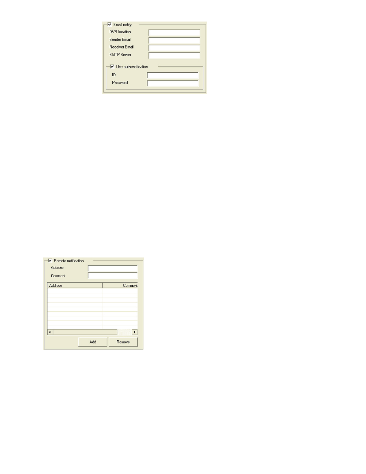
By checking E-mail Notify the user can have the DVR send notification when an event occurs.
Event notifications can be sent to more than one person. Just place a semicolon ; aer each person’s email ad-
Many SMTP Servers require authentification to prevent hacking by unauthorized users. If your mail server
requires authentification enter ID and password here. Please check with you Email administrator if you are
not sure if authentification is used.
Remote Notification is used to notify a remote client of an emergency event. Enter the remote client’s static
IP address and any comments to identify the remote client. A maximum of 20 clients can be set up for notifi-
cation.
E-Mail Notification
Page 42
34
Alarm Setup
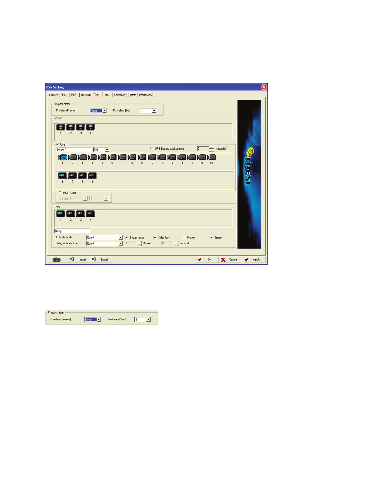
e alarm setup page allows the user to configure pre and post event recording, assign cameras to alarms
and set the event which activates the alarm or relay. e CDVS-7300 series has 4 alarms and 4 relays while
the 7500 series has 16 alarms and 16 relays.
Pre/post alarm frame buffering allows the user to set the number of frames buffered before and aer an
alarm or motion event occurs.
buffering, Middle setting allows for 240 frames (for all cameras) buffering and High setting allows for 360
frames (for all cameras) buffering.
event ends.e post alarm setting is from 0 to 59 seconds.
Pre/Post Alarm
Page 43
35
Sensor Setup
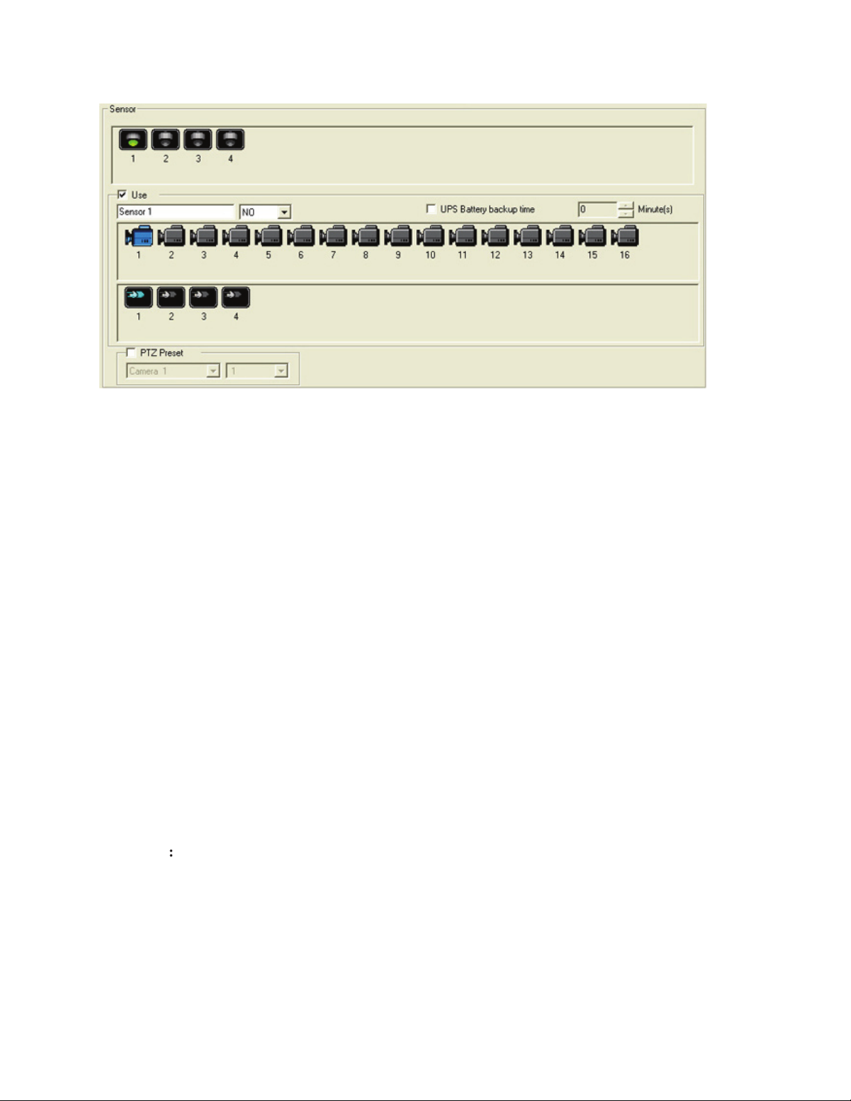
Select the sensor you want to set up. e sensor icon will turn green when it is selected. If
multiple sensors are selected the values will apply to all selected sensors. CDVS-7300 series DVRs only have 4
sensors. CDVS-7500 series DVRs have 16 sensors.
2.
Activate Sensor:
Turn on the selected sensor by placing a check mark in the Use check box.
3. Name Sensor:
Enter a name to identify the sensor.
4. Sensor Type
Enter the sensor type as NO-normally open or NC-normally closed.
5. Assign Camera:
Select the camera or cameras to associate with the selected sensor. Any number of cam-
eras can be associated with a sensor. A camera can also be associated with multiple sensors. For example if
you want cameras 2 and 3 to record when sensor 1 is activated. Select Sensor 1 it will become highlihted, next
click both camera 1 and camera 2. eir icons will turn blue indicating that they have been selected.
6. Assign a Relay:
Select the relay or relays you want to activate when the sensor has an event. If no relay
activation is desired then unselect all relays.
7. PTZ Preset
e DVR has the ability to call a preset from a PTZ camera when there is an alarm event. To
activate this function, click the check box for the PTZ preset, select the PTZ camera and select the camera’s
preset to call.
8. UPS Battery Backup Time:
is feature allows the system to receive a signal from a UPS when there is a
power outage. Place a check mark in the check box and select the number of minutes to wait before shutting
down the system. Aer the designated time, if the relay is still active, the system is shutdown automatically.
Page 44
36
Relay Settings
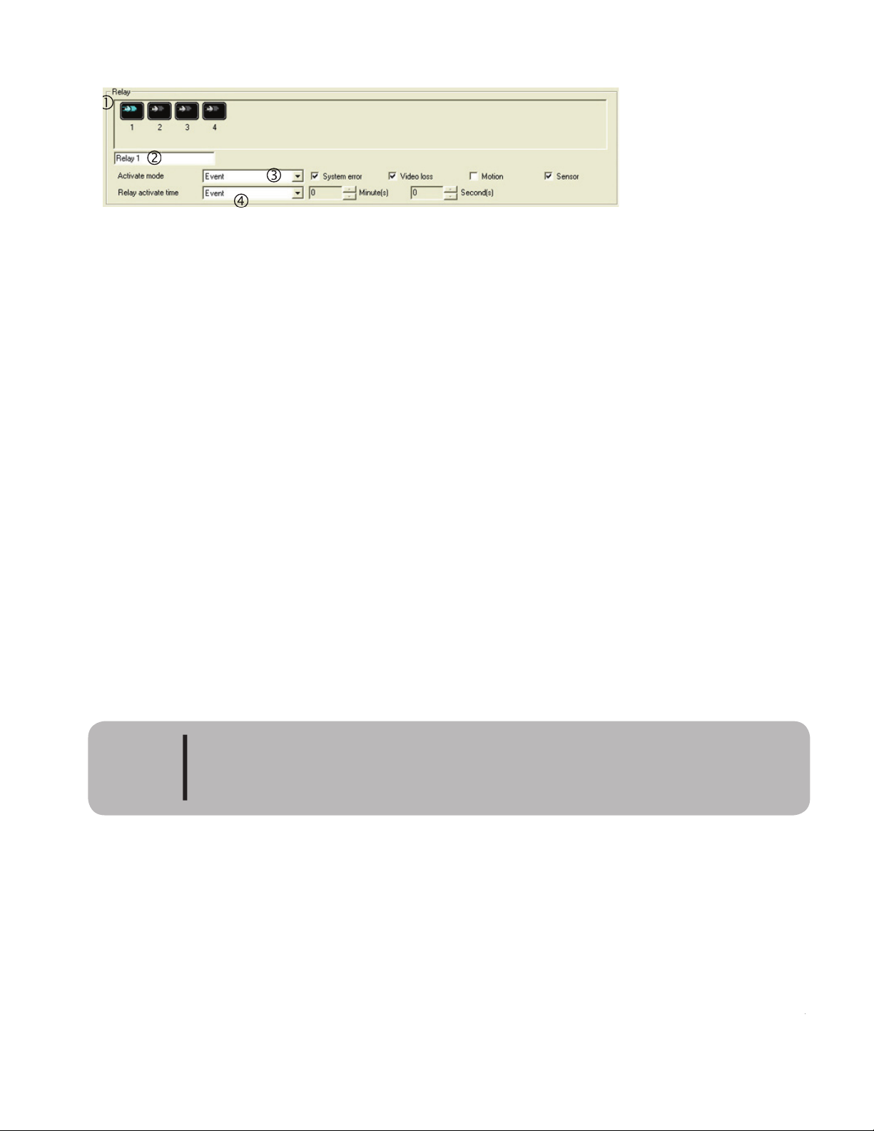
2. Relay Name: Enter a name to identify the corresponding relay.
3. Relay Activation Mode: Select the method for activating the relay. ere are three types - manual, event or
schedule.
• Manual: Relay will activate only when the user clicks the relay icon at the bottom of the main
screen. Please see chapter 1 for information on main screen features.
• Event: Relay will activate when there is an event. It will stop when the event is
terminated.
Event Types
1) Detected system error.
2) Camera signal disconnection.
3) Motion detection.
4) Sensor detection.
• Schedule: e relay will automatically activate/deactivate by the settings in the Relay Schedule.
Please see the section on Schedule Setup for information on setting up the relay schedule.
4. Relay Activate Time:
is allows the user to determine the amount of time the relay will stay active.
• Manual: e relay will be active until the administrator stops the relay manually.
• Event: e relay will activate when the event
starts and will deactivate when the event
terminates.
• Timer: e relay will activate on an e
vent and continue to be active for the time set by the user
When the user selects timer from the relay activate time drop down box the min/sec boxes will
activate allowing the user to enter a time in min/sec for the relay to run.
Please note that the admin level user can forcefully disconnect a relay when the
relay activation mode is set to schedule. Also if schedule is used the system will
not activate the relay when motion or camera loss is detected.
NOTE
Page 45
37
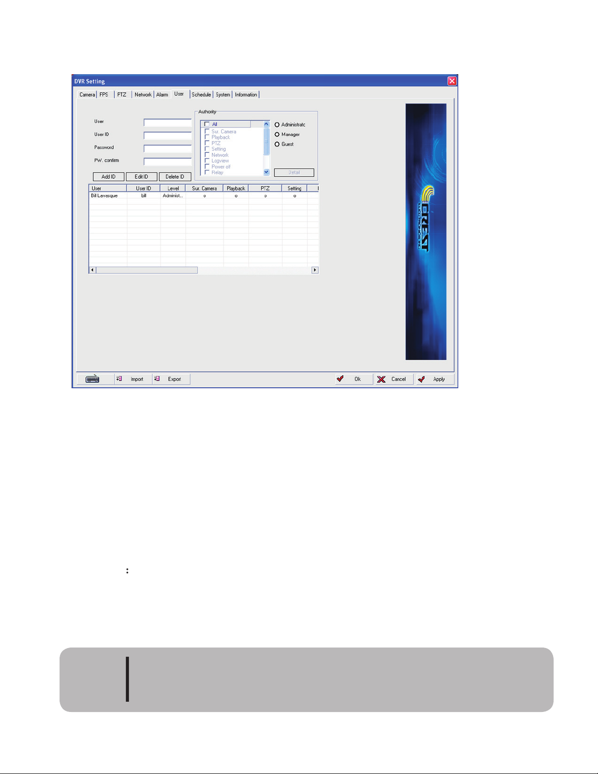
e system allows for an unlimited number of users . ere are three levels of predefined users - Admin,
Manager and Guest. e user id and password can only be 7 characters in length.
ADMIN:
Admin is the highest level of user. e first user to be set as admin must have the
Surveillance Camera and the settings boxes checked. e system will gray out these settings not
letting them be selected. is is done so the user will not lock himself out of the system. A user
with the admin can modify, add or delete any other level of user.
MANAGER:
Manager is the second highest level of user. A user with the manager level can edit
system functions but cannot change other users.
GUEST
Guest level user is the lowest level of user. A user with the guest level of authority is
limited to monitoring live video, searching and networking functions.
Please note that if an admin. user is not added the factory default user and pass-
word (system / manager) will still work. To disable the default user, a user with the
admin. level must be added to the system.
CAUTION
Page 46

38
Add User
To add users follow the steps below:
• User: Add the user’s name in this field. is is used to identify the user.
• User ID: Enter an ID for the user. is is the name the user will use when logging into the system.
e user id can only be 7 characters long.
• Password: Enter a password for the user. Can only be 7 characters in length.
• PW Confirm: Re-enter the user’s password.
• Authority: Select the user level and make the necessary changes to the rights.
• Add user: Click the Add User button to add the user
Edit User
To edit users, follow the steps below:
• Select the user to edit from the user grid; the entire user line will be highlighted.
• Make the necessary changes to the user from the authority list.
• Click the edit user button. e changes will be reflected to the right of the user’s name in the
users grid. A 0 (zero) indicates that the user has the corresponding right; X means that this right
has not been assigned to this user.
Delete User
To delete a user, follow the steps below.
• Select the users to delete from the user grid.
• Click the Delete User button.
• e user will be removed from the user grid.
Only a user with Admin level of authority can add or delete a user.
CAUTION
Page 47
39
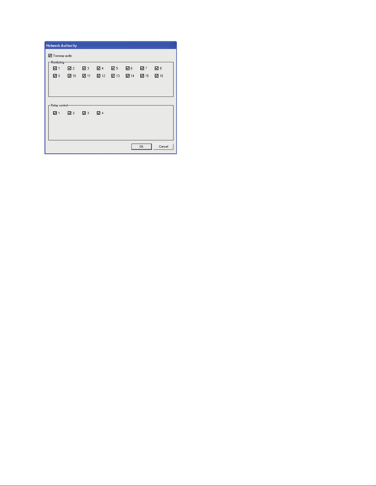
Detail Authority
Detail authority controls the following remote features:
• Two way audio: turns on or off the user’s ability to use the two way voice call.
• Monitor: Allows the system to limit the user’s ability to view cameras remotely. Check mark by
camera number means enabled.
• Relay control: Place a check mark by the relay number to give the user the ability to control relay
remotely.
Page 48
40
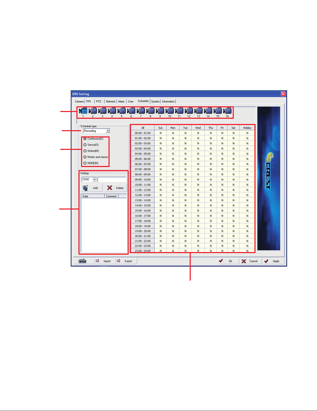
e
schedule setup window is used to set up when, and under what conditions, each camera will record
video. Recording can be scheduled by hour, day, and by type. is screen also allows the user to set up the
relay and remote notification schedule. e image below shows the sched ule window.
select camera
select event
Set Holidays
schedule grid
schedule type
e schedule setup screen allows the user to set up three different types of schedules. ey are 1)
recording, 2) Relay and 3) Notification. Below is a detail explanation of each type of schedule.
Recording Schedule
e system allows for several different types of recording modes. e following is a list of the dif-
ferent modes available.
Continuous Recording: Symbol - C Color - Blue
Sensor Recording: Symbol - S Color - Red
Motion Recording: Symbol - M Color - Yellow
Motion & Sensor Recording: Symbol - M+S Color - Orange
No Recording: Symbol - N Color -
White
Page 49

Continuous Mode Recording
In continuous mode recording, the selected camera’s video is saved based on the recording schedule set up
in the recording schedule grid. It is possible to set by hour or day. To set a continuous re cording schedule
use the following instructions.
1.) Select camera or cameras.
2.) Click the CR (C) radio button.
3.) Click and drag the mouse icon in the recording schedule grid to select the days and hours for
op eration. To select all, click the all button in the upper left corner of the recording grid.
Day and time selected will display in blue with the C symbol indicating the time and day selected.
Setting the schedule grid will not by itself activate recording by schedule. e
recording type box on the camera setup screen must also be changed for each
camera to schedule. Please refer to Camera setup earlier in this chapter.
CAUTION
Sensor Recording
Sensor alarm only records video for cameras set up for and linked to sensors. Recording begins when sensor
is ac ti vated and con tin ues for duration of alarm. is recording mode is used when the user only wants to
record video when there is a sensor activation. It is possible to set sensor by hour or day. To ac ti vate sensor
recording use the following instructions.
1). Select camera or cameras.
2). Click the SR (S) radio button.
3). Click and drag the mouse icon in the recording schedule grid to select the days and hours for
operation. To select the entire time and date grid, click the all button in the upper le corner of
the recording grid.
Day and time selected will display in Red with the R symbol indicating they have been se lected.
Setting the schedule grid will not by itself activate recording by schedule. e
recording type box on the camera setup screen must also be changed for each
camera to schedule. Please refer to Camera setup earlier in this chapter.
CAUTION
Page 50

Motion Recording
Motion recording records video only when motion is detected. Cameras where there is no motion will not
be recorded. is is the most used method of recording, as the system does not record until there is motion
in the selected areas (see motion area setup). It is possible to set by hour or day. To activate motion recording
use the following instructions.
1). Select camera or cameras.
2). Click the MR (M) radio button.
3). Click and drag the mouse icon in the recording schedule grid to select the days and hours for
op eration. To select all, click the all button in the upper le corner of the recording grid.
Day and time selected will display in yellow with the M symbol indicating they have been selected.
Setting the schedule grid will not by itself activate recording by schedule. e
recording type box on the camera setup screen must also be changed for each
camera to schedule. Please refer to Camera setup earlier in this chapter.
CAUTION
Motion and Sensor Recording
Motion and sensor recording combine both motion and sensor re cording. If a camera has a sensor or motion
event the system will record video. It is possible to set by hour or day. To activate motion and sensor record-
ing use the following instructions.
1). Select camera or cameras.
2). Click the M+S radio button.
3). Click and drag the mouse icon in the recording schedule grid to select the days and hours for
op eration. To select all, click the all button in the upper le corner of the recording grid.
Day and time selected will display in orange with the M+S symbol indicating they have been selected.
Setting the schedule grid will not by itself activate recording by schedule. e
recording type box on the camera setup screen must also be changed for each
camera to schedule. Please refer to Camera setup earlier in this chapter.
CAUTION
Page 51
43
Schedule Recording Example:
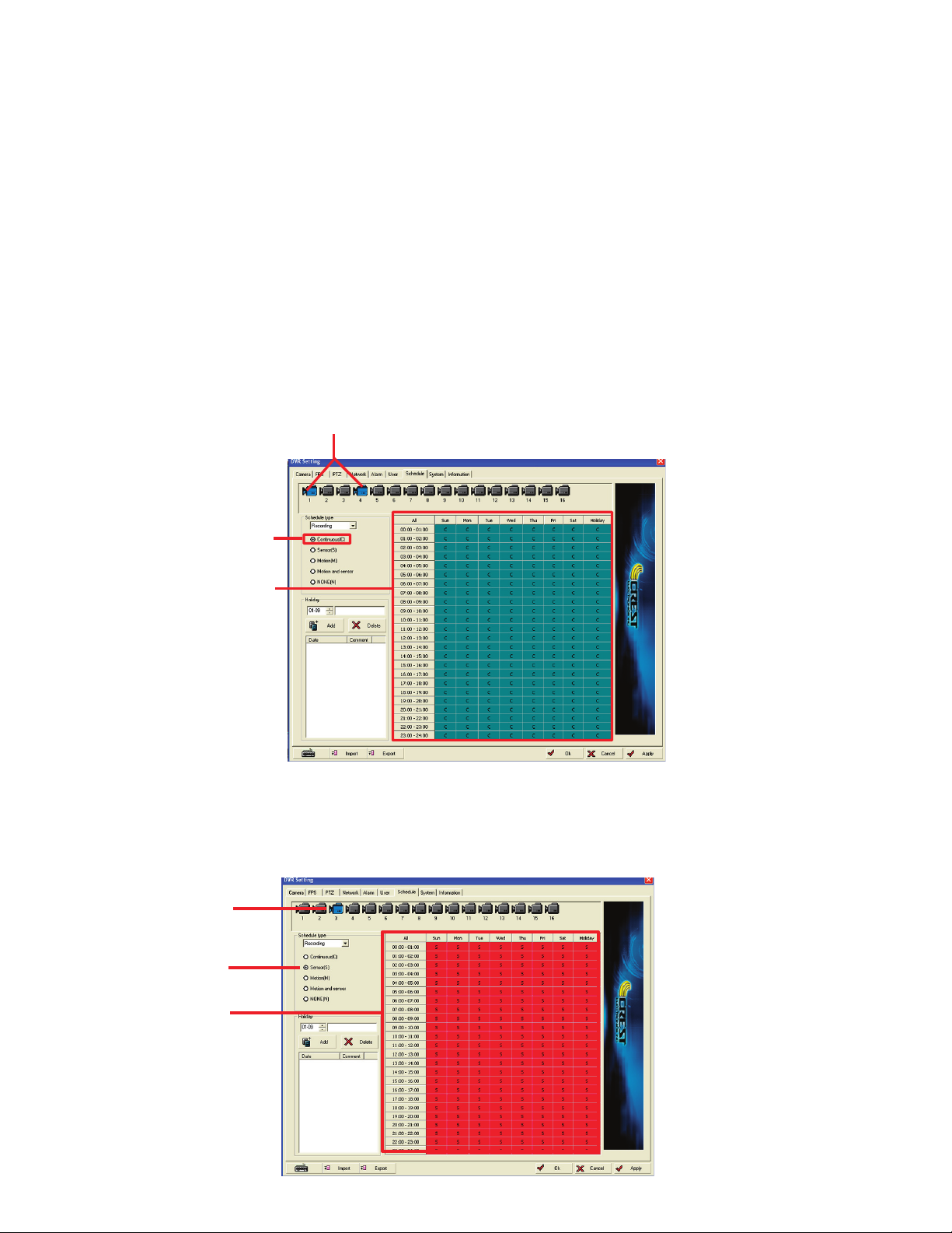
e following example will detail setting up cameras 1 & 4 for Continuous re cording, camera 3 for sensor
recording, cameras 2,5,6,7,8 for motion recording, and camera 8 for no recording between 9:00-9:59am and
motion recording the rest of the time. Please note that the recording type on the camera setup screen should
be set to schedule. You will also have to set the motion grid for cameras 2,5,6,7,8 on this page.
We are going to set camera one and four to record in continuous mode. 1). We need to select camera one and
four. We do this by clicking on camera one to highlight it. en holding down the control button (CTRL) on
the keyboard we will click camera 4. is will select both camera one and four (they are highlighted in blue).
2). We need to set the recording mode to continuous mode. Do this by selecting the radio button continu-
ous (C). 3). We now will set the days and time for recording these cameras in con tinuous mode. Because we
want these cameras to record everyday, 24 hrs a day, we will click all in the upper le corner of the day and
time schedule grid. e entire grid will turn blue and every hour will have a C indicating continuous mode
as the image below shows.
Now we need to set camera three for sensor recording. 1). Select camera 3. 2). Click sensor radio button to
select sensor recording, click and drag to select the entire schedule selection grid. Grid will turn red with
each hour displaying S indicating sensor recording mode. See image below.
camera 3 selected
sensor recording
selected
time and date set to
sensor record
Continuous mode selected
Time and date grid set
to continuous
mode
cameras 1 & 4 selected
Page 52
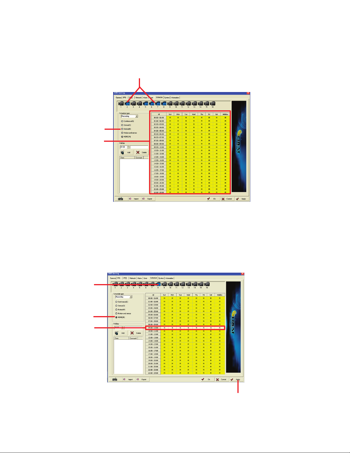
We next need to set cameras 2,5,6, and 7 for motion recording. We will also select camera 8 because it will
record in motion except for one hour starting at 9:00 am. 1). Select cameras 2,5,6,7,8. 2). Select the motion
recording radio button motion (M). 3). Click all in the upper le corner of the recording selection window
to select the complete grid. Grid will turn yellow and the hour cells will contain a M indicating that they have
been selected for motion recording as indicated by the image below
cameras 2,5,6,7,8 selected
motion recording selected
time and day grid displays
yellow with a M indicating
motion
recording
Next we need
t
o set the schedule to not record for 9:00 am for camera eight. 1). Click camera eight. 2). Click
None (N) recording mode radio button. 3). Click 9:00 to select from 9:00 am to 9:59 am. e cells for the
9:00 hour turn white with a N indicating no recording. 4). Click apply button to save the changes you made.
Image below displays these changes.
camera 8 selected
no recording selected
select 9:00, cells dis-
play in white with N
select the apply button to save changes
e last step is to set your motion grid and sensitivity for cameras 2,5,6,7,8. is is done in the camera setup
screen which was covered earlier in this chapter.
Page 53
45
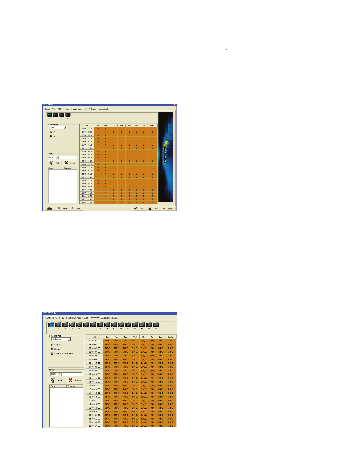
Relay Schedule
Relay schedule tells the system when to automatically activate a relay. e relay will continue to be active
until the schedule turns off the relay. To turn on a relay, select the rela
y and click the relay radio button then
select the day and time to have the relay turn on. An
O indicates that the relay is turned on; X in
dicate
s that
the relay will be off. Please see image below.
Please note that the Admin can override
the relay schedule by using the relay buttons a
t the bottom of the
main screen.
Event Notification Schedule Setup Window
is window allows the user to set by day, hour, and event when to notify a remote client via email of an
emergency situation such as an alarm event. Using this schedule will prevent the user from getting unwanted
event notifications, such as during normal business hours. ere are three events the remote client can be
notified of: Sensor, motion, and video loss. e user can choose any combination of these. Please see image
below
Page 54
46
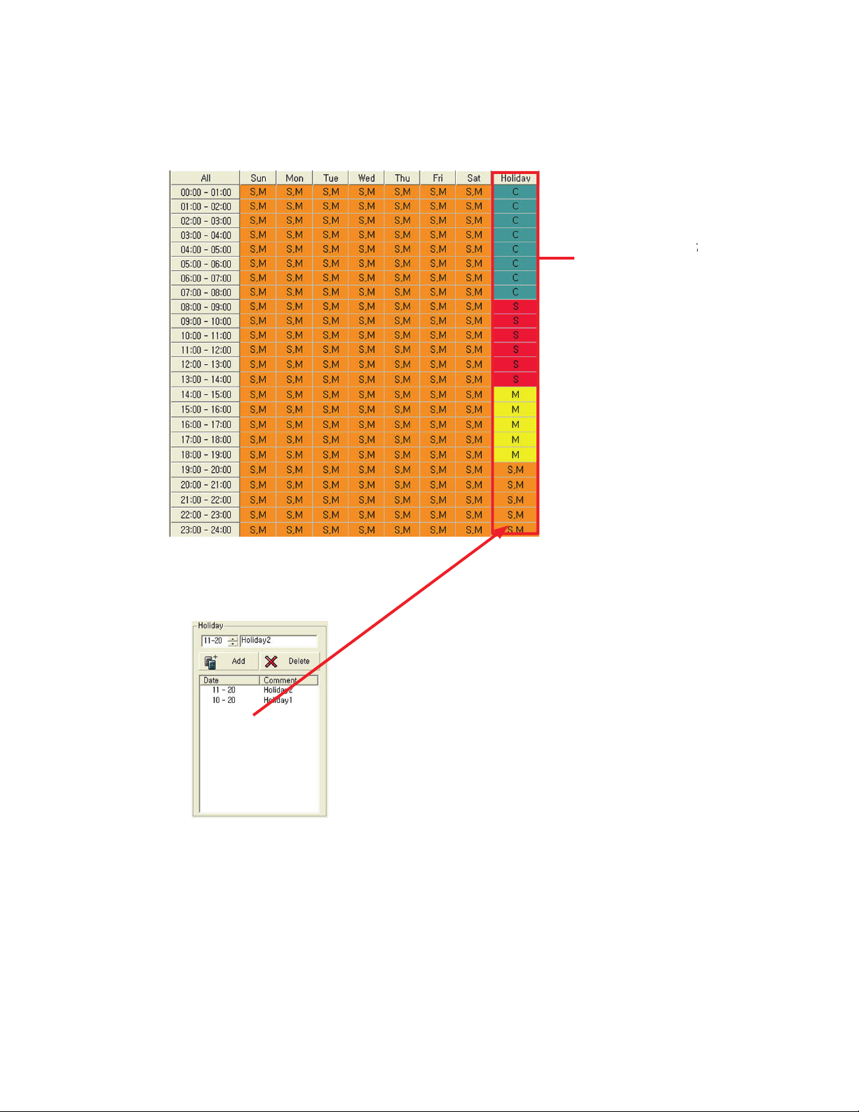
Holiday Schedule
Holiday schedule allows the user to set a specific date as a “Holiday”. e schedule will then follow the set-
tings labeled “Holiday” on the grid table. Please see image below.
Make your settings
f
or the holiday
in the holiday column as desired
dd the date to the holiday schedule. When the date arrives the
schedule will follow the settings in the holiday column. Aer the holi-
day the system will go back to the regular schedule
Page 55
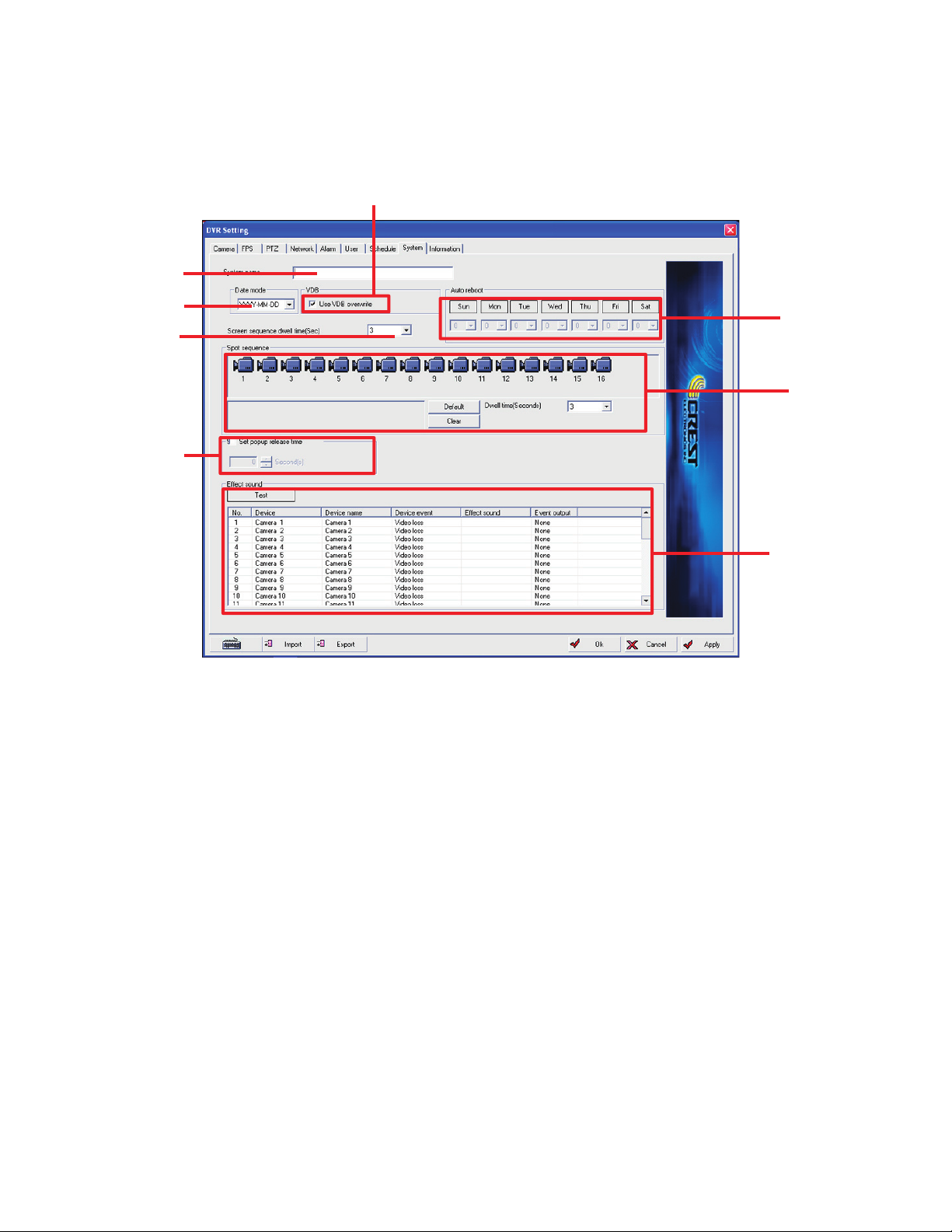
47
e system settings window is where the user sets global settings for the DVR. e image below shows the
functions of the system settings window.
system name
date mode
main screen
sequence
dwell time
pop up release
time
auto reboot
s
pot output
sequence
sound effect setup
System Name
System allows user to give the DVR a name to distinguish it from other systems. is is very useful when
connecting to multiple DVRs remotely.
Date Display
e system allows the user to change the date display. e available options are:
• Year, Month, Day : YYYY-MM-DD
• Month, Day, Year : MM-DD-YYYY
• Day, Month, Year : DD-MM-YYYY
Automatic Rebooting
is allows the user to specify a time to automatically reboot the system. User can select multiple days and
time or single day and time for rebooting the system.
VDB Overwrite
By checking this box the system will overwrite existing recorded data when all hard drive space is used. e
system will overwrite the first file and continue in order until the last VDB file is overwritten. It then repeats
the cycle. For information on VDB files, see Make VDB in chapter 3.
VDB overwrite
Page 56

48
Main Screen Sequence Dwell Time
When using the sequencing feature on the main screen this controls the amount of time each screen is dis-
played before moving to the next view. e options are 3,5,10,15,20,30 seconds. If there are any cameras that
are not used (turned off) they will be excluded from the rotation.
Spot Out Sequence
e user can control the order in which the cameras are sequenced through the spot out. To place a camera
in the spot out sequence, click on the camera and it will be transferred to the spot sequence grid. A camera
can be placed in the sequence more than once. To clear the sequence grid, click the clear button. To quickly
put all cameras into the grid in natural order click the default button. Set the dwell time in seconds; the op-
tions are 3,5,10,15,20,30.
e CDVS-7300 and CDVS-7500 series DVRs display differently if no cameras are selected (grid is blank).
e CDVS-7300 will display only camera 1 if there are no cameras in the grid. e CDVS-7500 will display
the same as the main screen. Example: If the main screen (Live view) is displaying 16 cameras then the spot
output will show the same screen. If the main screen (Live view) is changed to display 4 cameras the spot will
change to display the same 4 cameras. If the user goes out of the main screen the spot still displays the cam-
eras that were showing on the live view before going to a different mode. It will not display setup screens or
search screens.
Pop-up Release Time
If the user has set the system to pop-up on screen a camera during an event, then this feature allows the user
to release the pop-up and return the screen to the previous display. e time for holding the pop-up is from 1
to 60 seconds.
Alarm Event Sound Effect
e system can sound an alarm based on the following events - video loss, motion detection or sensor activa-
tion. To activate sound first select the event from the device colmun for the selected camera. en select the
event output, the choices are - none, effect sound or beep. If effect sound is chosen then select the desired
sound from effect sound column. Aer choosing, the sound can be tested by clicking the test button.
Page 57
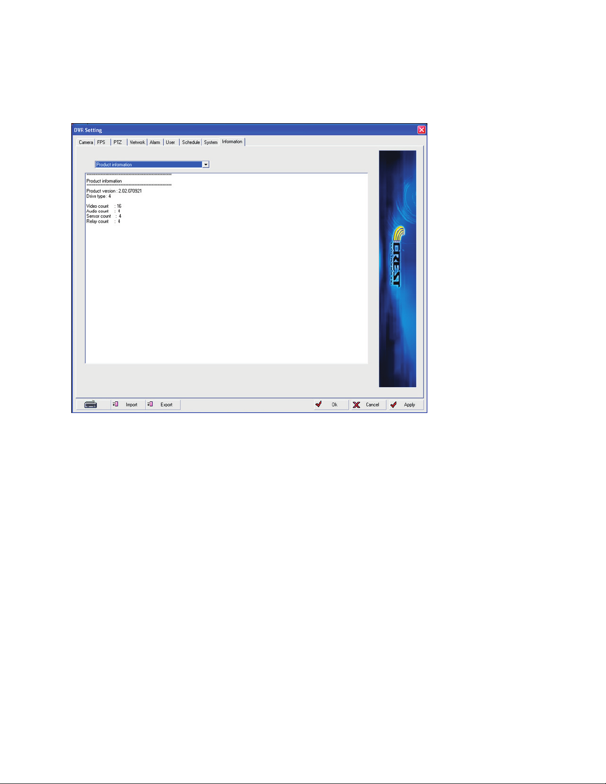
49
e information screen displays the various system information. It is broken down into the following five
categories - product information, Network information, VDB database information, system information, and
memo.
Product Information
Contains information relating to the DVR system. It displays the board quantity, number of channels,
number of audio channels, number of sensors and relays. It also contains the soware version number.
Network Information
Lists the various network related information such as host name, DNS server, TCIP settings, IP address, net-
work adaptor, MAC address, etc.
VDB Information
Display information related to the video database files (VDB).
System Information
Displays the specific DVR hardware information such as OS, computer name, RAM, CPU, DirectX version
number.
Memo
Allows the user to place notes into the system.
Page 58

3
Page 59
51
e purpose of the system environment setup shell is to allow the user to interface with the OS to set various
functions such as networking setup, modem setup, printer setup, time setting, etc. e main desktop screen
is shown below.
Entering the Environment Desktop
To enter the environment desktop:
• Click the main screen exit button. e system shutdown pop-up appears.
• Click program shutdown, the system will exit into the desktop screen. During the closing
process the DVR will display a message “destroying drivers” and “closing log files”. Aer this is
completed the screen above will be displayed.
• Click the start button to bring up the desktop menu.
Page 60
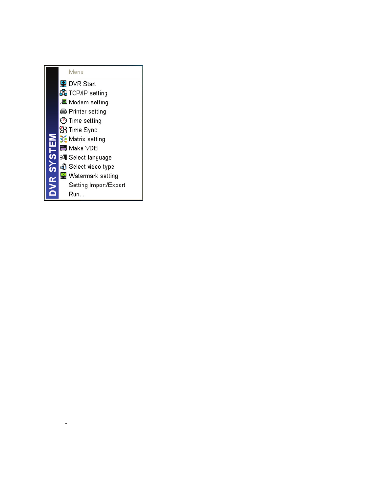
52
Overview of Environment Setup Functions
Click the start button on the environment desktop to bring up the desktop pop-up menu as shown below.
DVR Start
Click this menu to restart the DVR program.
TCP/IP Setting
Use this menu to setup the network environment in the OS. Please refer to the appendix for information on
setting up the DVR for network usage.
Modem Setting
Setup modem environment for using a dial up modem.
Printer Setting
Use this menu to install or edit a printer.
Time Setting
Use this menu to set the time environment in the OS. Please note that changing the date and time could
cause the DVR system to erase existing files.
Time Sync
Use this menu to connect the DVR to a time server.
Page 61
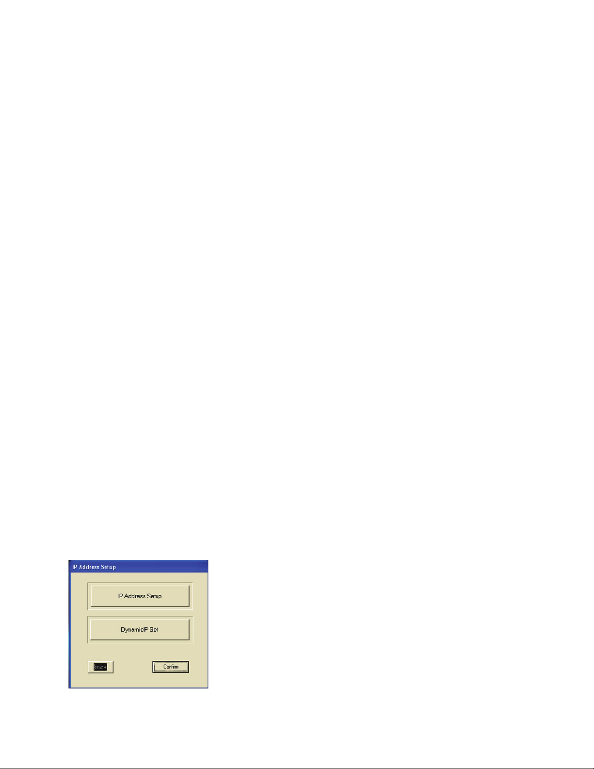
53
Matrix Setting
Current physical camera channel number can be changed to another logical camera channel and provides
setting menu for linking audio channels to cameras.
Language Setting
Menu allows user to change the language displayed in the DVR GUI.
Video Type Setting
Setting mode of camera type NTSC/PAL is supported.
Watermark Setting
Allows the user to change the design of the watermark symbol that checks for illegal or modified video.
Setting Import / Export
Allows the user to backup the basic environment settings to a file.
Ru
Command line for use by system.
TCP/IP Settings
Click the TCP/IP settings button to bring up the TCP/IP set screen. e screen has two options TCP/IP
setup or Dynamic IP setup. Use the TCP/IP setup for setting up normal IP networking. Use the dynamic to
set up a DDNS network.
Page 62
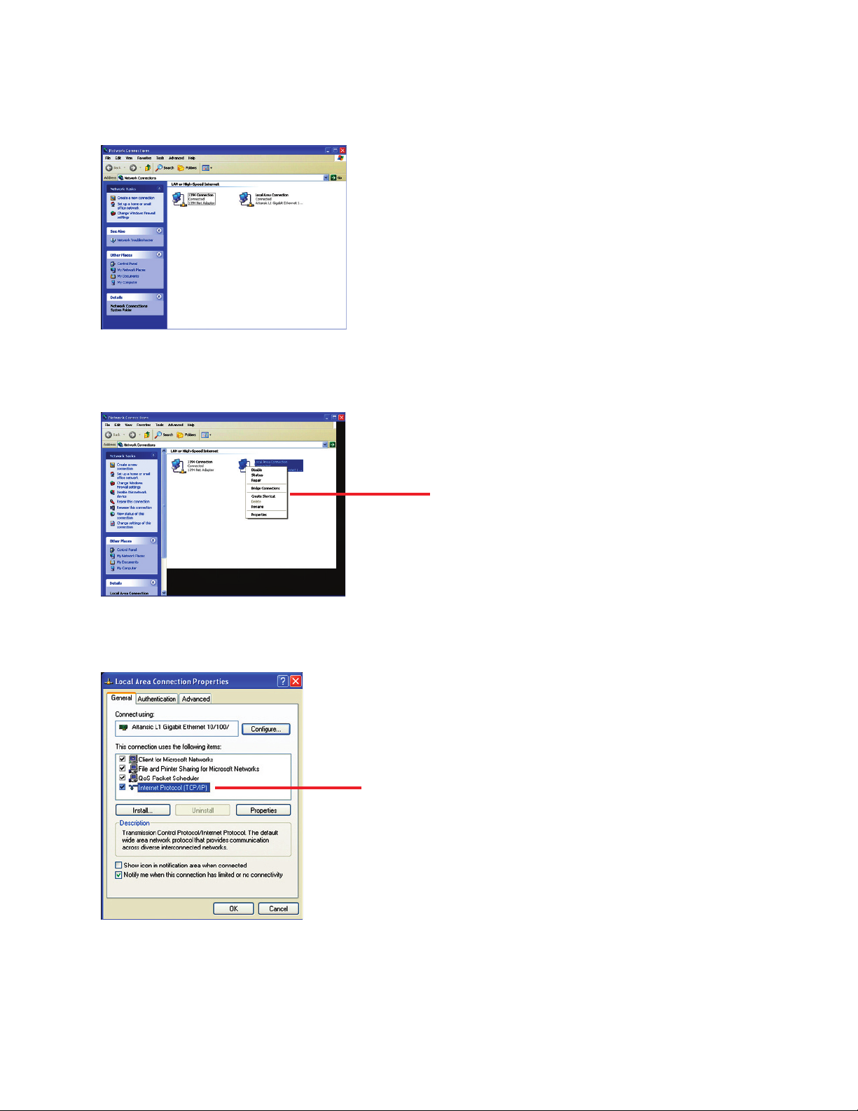
54
IP Address Setup
• Click the IP address setup button to get into the OS Network setup screens.
• Right click on your network adaptor to get the network adaptor drop down box.
network adaptor dropdown box.
• Click the properties menu.
• Highlight and double click Internet Protocol (TCP/IP)
double click Internet Protocol (TCP/IP)
Page 63
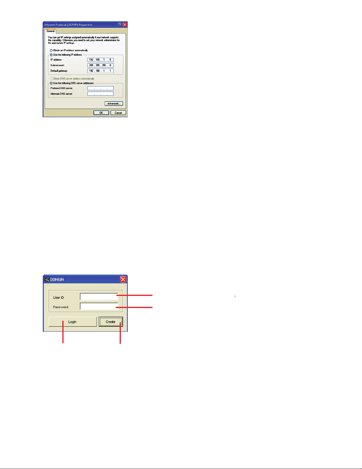
55
• Enter the IP address for the DVR in the IP Address line
• Enter the Subnet Mask in the subnet mask line.
• Enter the default Gateway in the default Gateway line.
• Enter the primary and alternate DNS servers address in the DNS box.
If you don’t know these settings please contact your network administrator. It is highly recommended that
you use a static IP address for the DVR. If Obtain IP Address Automatically is used and the DHCP server
assigns the DVR a different address than the one originally assigned the DVR will not be able to connect to
the remote soware. For a more detailed discussion about networking please refer to the appendix.
Setting Up DDNS
To set up a DDNS on the DVR click the Dynamic IP setup button from the main TCP/IP menu.
Enter username for DDNS server
Enter password for DDNS server.
login to account
create a new account
Page 64
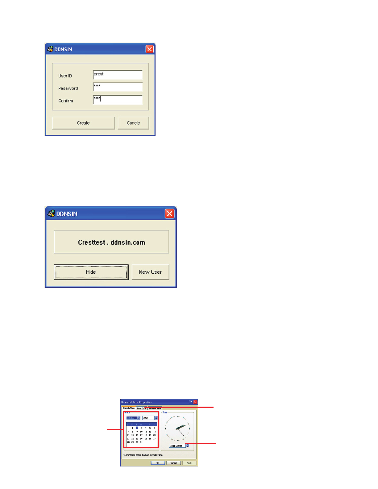
56
To create an account click the Create button
Enter a userID and password for the new account and click create. e system will go and check with the
DDNS server to see if there is another user with this user id. If so it prompts for another user id and pass-
word. If not the DDNS server creates the account as shown below.
Click hide button to hide the DDNS account screen. Your new account with DDNSIN is now ready for use.
Remember to write down the user id and password as you will need it when connecting remotely. Your
DDNS will run automatically when the DVR is started. If for some reason it gets disconnected just login at
the main DDNS setup screen.
Time Setting
Time setting function allows the user to set the date and time zone in the OS for the DVR. To use the time
setting function click the time setting menu. is brings up the OS date and time properties box.
set day, month, and year
set hour, minute, and am/pm
time zone tab
Page 65
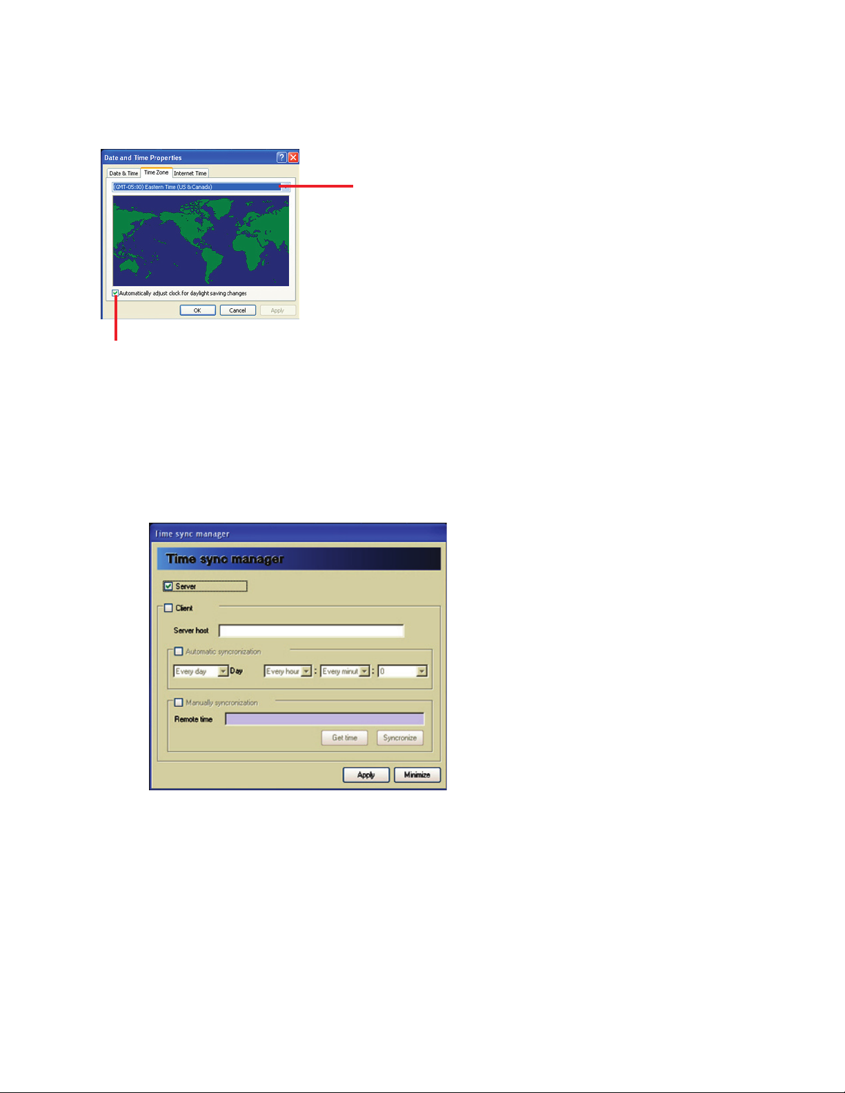
57
Set the day, month, year then set the hour and minute. Next click the Time Zone tab to bring up the time
zone properties box. Click the dropdown box and select the proper time zone for your area. Click the auto-
matically adjust clock for daylight savings changes box. Click the apply button then the OK button to close
the time settings property box.
select the proper time zone.
click daylight savings time check box.
Time Sync.
e time sync manager allows the DVR to connect to a time server so all DVRs in a system will have the
same time. If you do not have a time server then you can use one of the DVR’s to be a time server. You can
set the DVR that will be your time server to time sync through the Internet Time feature of the date and time
properties box shown above. To set up Time Sync follow the instructions below.
• Bring up the Time Sync Manager by clicking on the Time Sync. menu button.
• Click either Server or Client check box.
• If server, click apply, then minimize.
• If client, then enter the ip address of the time server in the server host box.
• If you want to automatically sync time, check automatic synchronization and enter day, hour,
minute and second for synchronization.
• User can choose to manually sync time; to do this check manual time sync box.
• Click get time to retrieve the current time from the time server.
• To get the current time and sync the DVR’s time with the server’s time click the Synchronize button.
Page 66
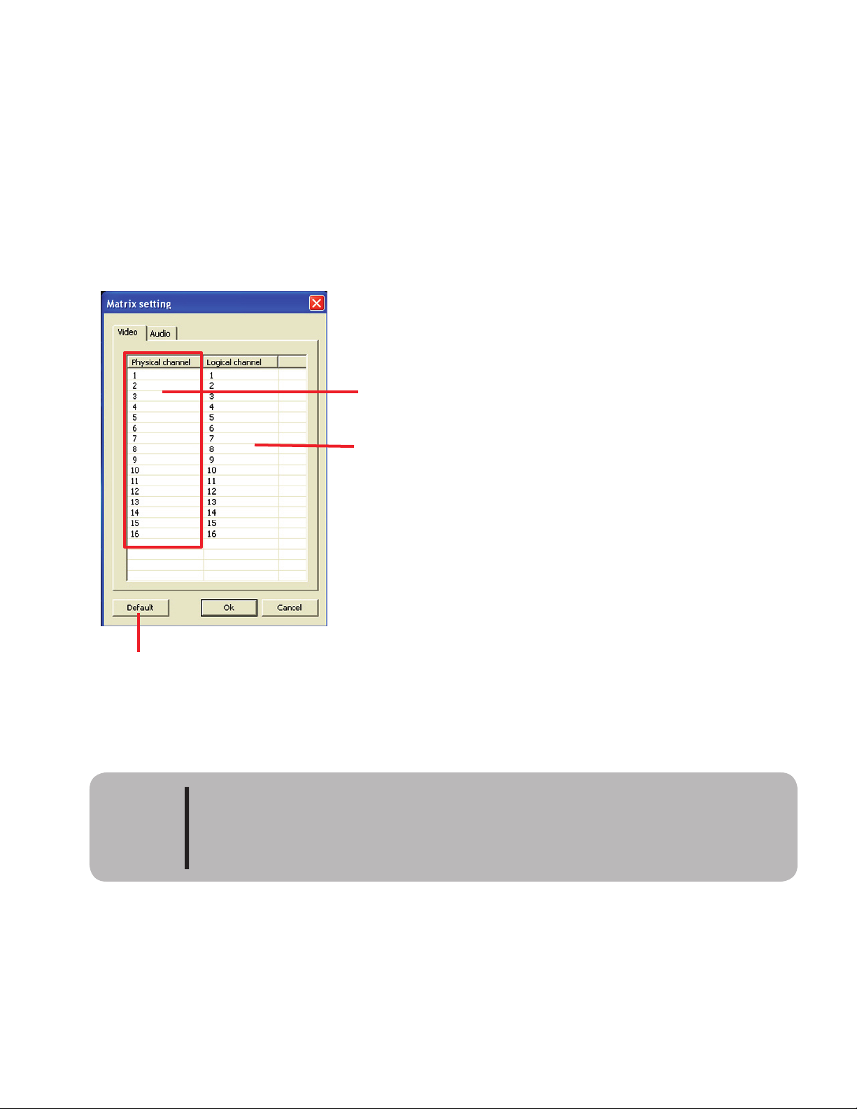
58
Matrix Setting
e Matrix setting allows the user to control the logical camera number with the physical port. It also allows
the user to assign audio ports to camera ports.
Camera Setting
Modify the physically set camera’s channel to a different logical port.
play as camera 1 automatically).
physical port address
logical channel address
change ports
back to default
Changing the physical port can be confusing. e system will be telling you events
happened to a logical camera number such as 5 but in reality the actual physical port
number the camera is connected to the box with is 1. It is strongly recomended that
you mark the physical ports with the new logical address.
CAUTION
Page 67
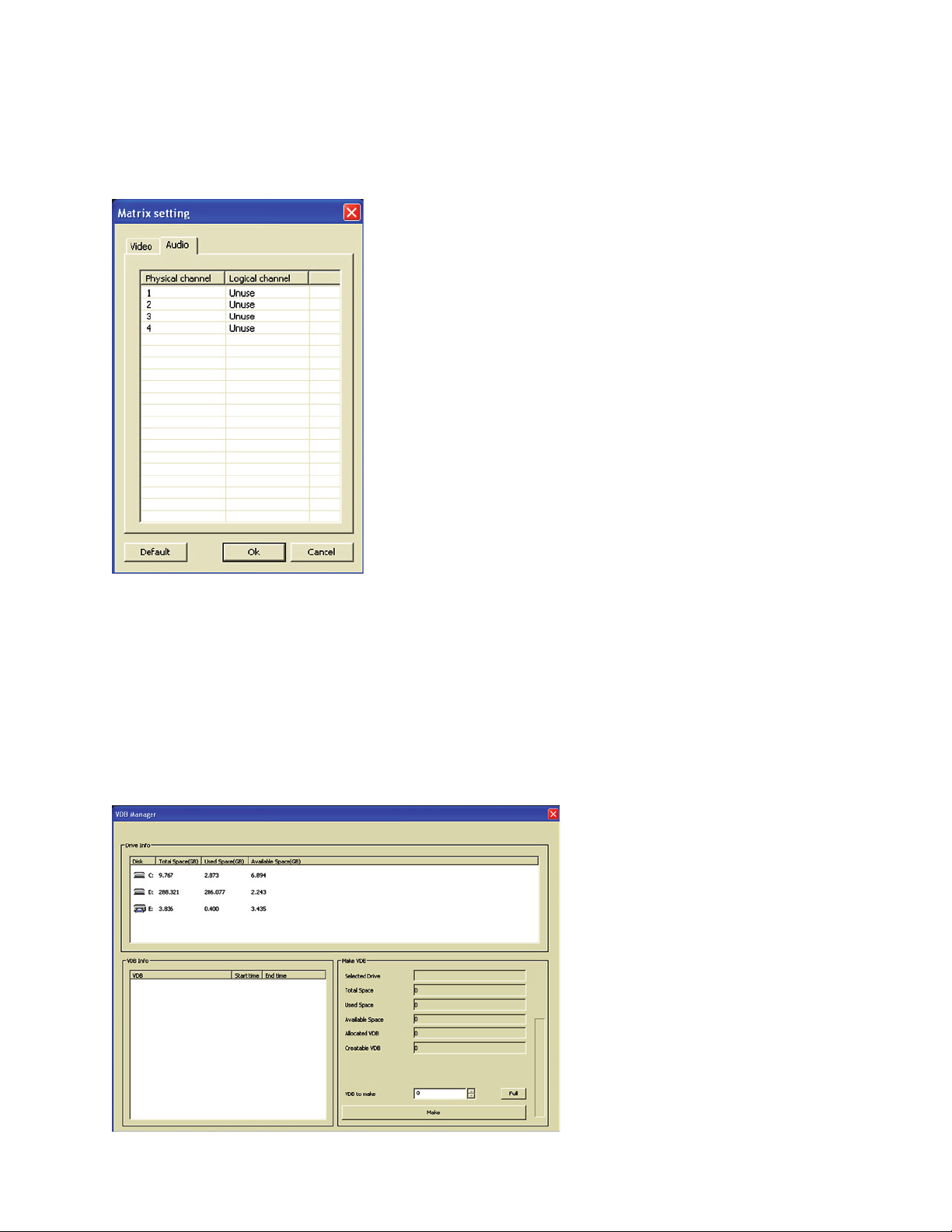
59
Audio Setting
Click the Audio tab to link a camera with an audio port. If the audio port is unused then leave it as unused
otherwise link a camera to the used audio port. A camera can be linked to only one audio port.
Make VDB
e VDB manager is used to create database files to hold recorded video. ese database files have been cre-
ated by the factory for all your hard drives. e only time you need to use this function is when adding a new
hard drive to your system. Do not use this function unless asked to do so by a factory technician. Doing so
could affect the recording and performance of your system.
Page 68
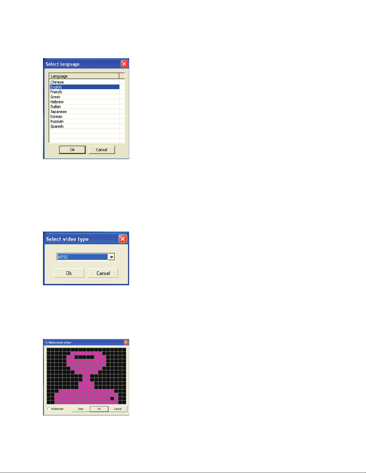
60
Select Language
Select the language to use.
Select Video Type
Select the video format used by your cameras. Either NTSC or PAL. Choosing the wrong format will cause
the DVR to malfunction.
Watermark Setting
Allows the user to edit the basic icon design of the provided watermark authentication stamp.
Page 69
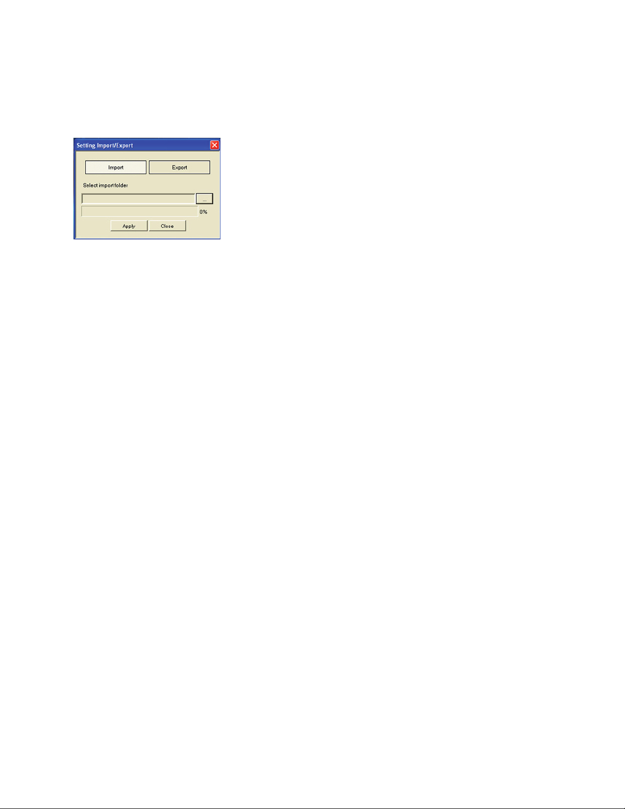
61
Setting Import / Export
Allows the user to make a backup of the environment settings. is function also allows for the importing
of the saved files at a later date. is function uses the explorer which allows the user to save to an external
device such as a USB stick.
Run....
is is a short cut line command prompt. is is intended for use by factory technicians.
Page 70

Page 71
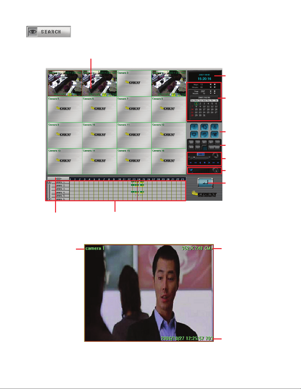
63
The image below lists the functions of the search screen.
Playback display area
Search menu options
Camera display options
Playback controls
Date
s
earch calendar
Current date and time
Audio volume and
advance search
Exit search
Hour and minute controls
umbnail
search
Camera name
Resolution and recording
method
Recording date and time
Page 72
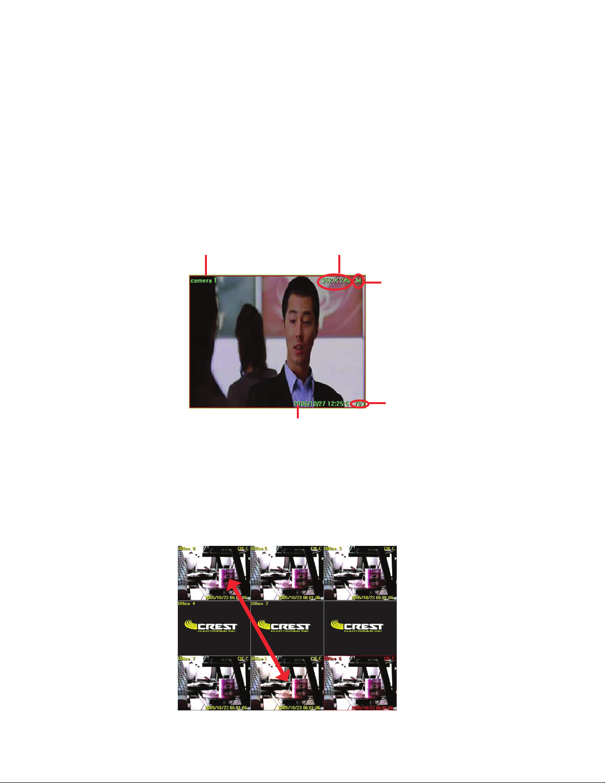
64
The search screen is used to review previously recorded video. When entering the
Search Screen
for the first
time, the system starts playing the last hour of recorded video. The system will display the maximum num-
ber of cameras your system was designed to have. If your system was designed for sixteen cameras, it will
display in 16 camera mode. If designed for 8, it will display 9 cameras with the ninth camera being blank. If
designed for four cameras, it will display in 4 camera mode.
Playback Screen
Each camera’s OSD (on screen display) shows the camera’s name, recorded resolution, method of re cording,
and time and date of recording as well as the frame number.
camera name
recorded resolution
method of recording
date and time of recording
The system allows the user to swap screens from one screen to the other. For example, if the user would like
to view camera 8 in camera one’s position, just click and drag camera one to eight’s position. The image
below shows camera eight, five, and three moved to the top row of the screen, and camera seven, one, and
six moved to the bottom row.
Screen Swapping
Recorded
frame
Page 73
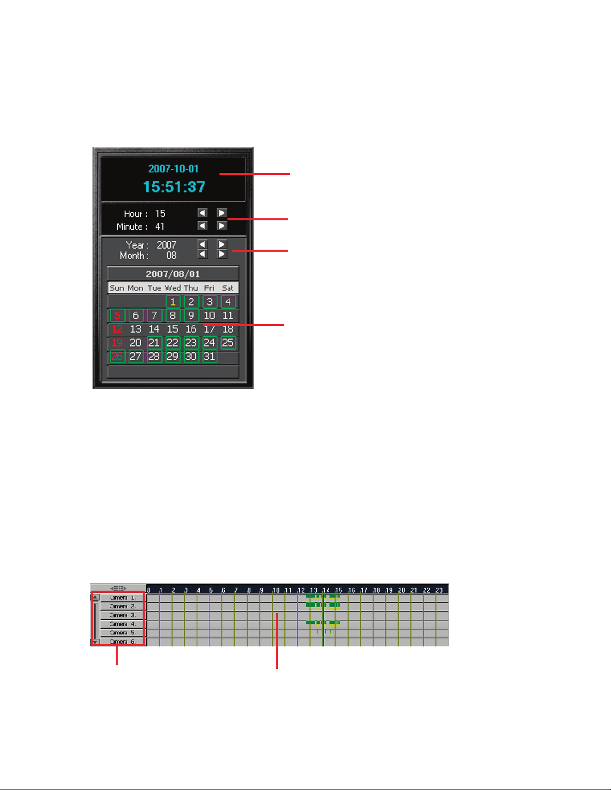
65
Search Screen Calendar
e search calendar allows the user to select the date by year, month, and day to view recorded video. If the
system has recorded video for a particular day it will be highlighted in green. e calendar has a short cut bar
that allows the user to choose the hour and minute to begin the playback. e image below shows the various
features of the search calendar.
Current date and time.
Select the hour and minute to begin playback.
Select year and month for video search.
Select the day for video search. Recorded video
will be highlighted in green.
Video Search Timetable
e timetable provides a timetable of recorded video for each camera channel. e timetable color codes the
method of recording for easy reference. e color codes are:
• Green - Video recorded in continuous mode.
• Blue - Video recorded with audio.
• Yellow - Video recorded in motion mode.
• Red - Video recorded in sensor mode.
Camera selection.
Timetable
Page 74
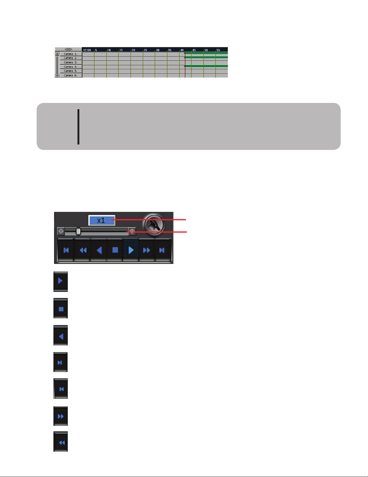
66
By clicking on a specific hour the timetable can be expanded for that hour giving the user a larger view of
recorded video for that hour.
Timetable expanded for 12:00.
Please note that the timetable will show video for partial minutes. Example: if there is
recorded video starting at the 10:02:55 and records for 10 seconds to 10:03:05 then the
timetable will show recorded video for 10:02 and 10:03 although there is only 5 sec-
onds of video recorded in either minute.
CAUTION
Video Playback Control
e video playback controls allow the user to pause, play forward, play backward, play one frame at a time
and control the speed of playback.
Indicates current playback speed.
Slider bar speed adjustment
Forward play button
Pause Button
Backward play button
Move forward one frame button
Move backward one frame button
Adjust speed forward button (1/8 - 1024)
Adjust speed backward button (1/8 - 1024)
Page 75
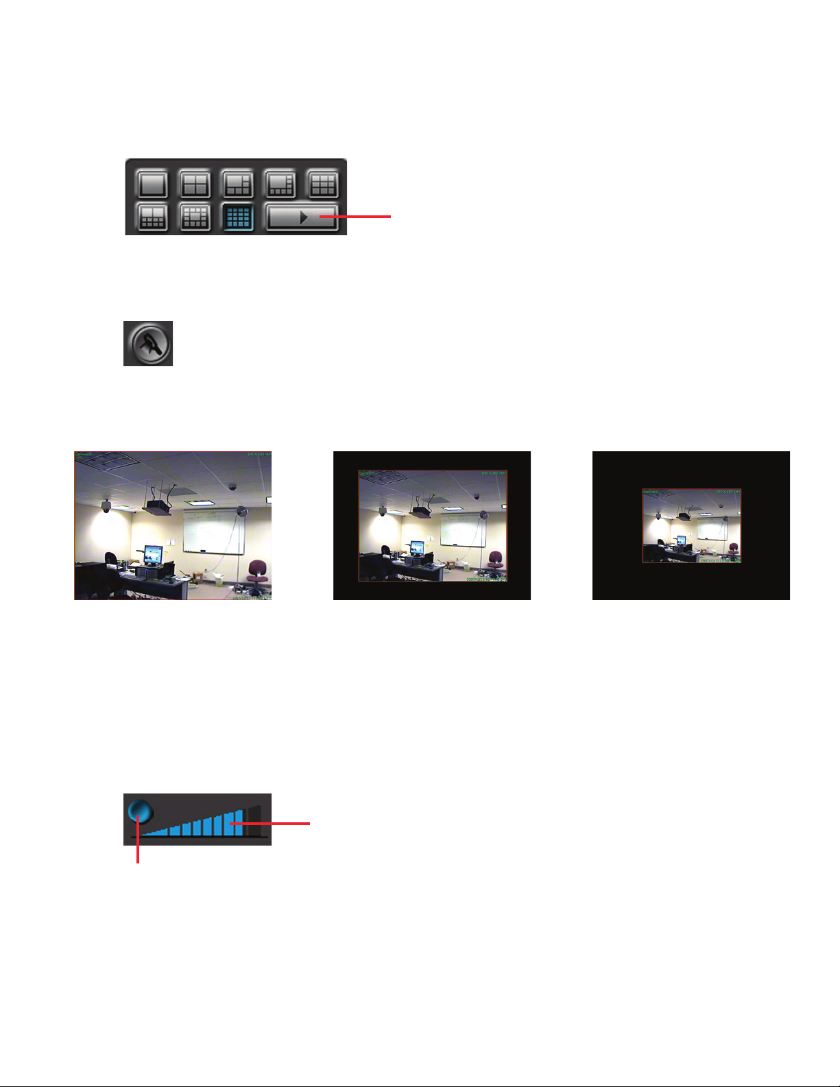
67
Screen Division Buttons
e search screen can be changed to one of the split screen modes. Use the next button to change to the next
camera when in single camera screen.
Next screen button
Zoom In/Out Button
Allows the user to enlarge or reduce the original picture.
Listening To Audio
Click the audio on/off button to listen to audio. e camera associated with audio must be the selected
camera to hear audio. Only one audio channel can be played back at time. Because audio and video must be
synchronized, playback must be a 1x playback for audio to be heard. e audio button will turn blue when
audio is on. Use the volume bars to increase or decrease the volume.
volume control
Audio on/off
Page 76
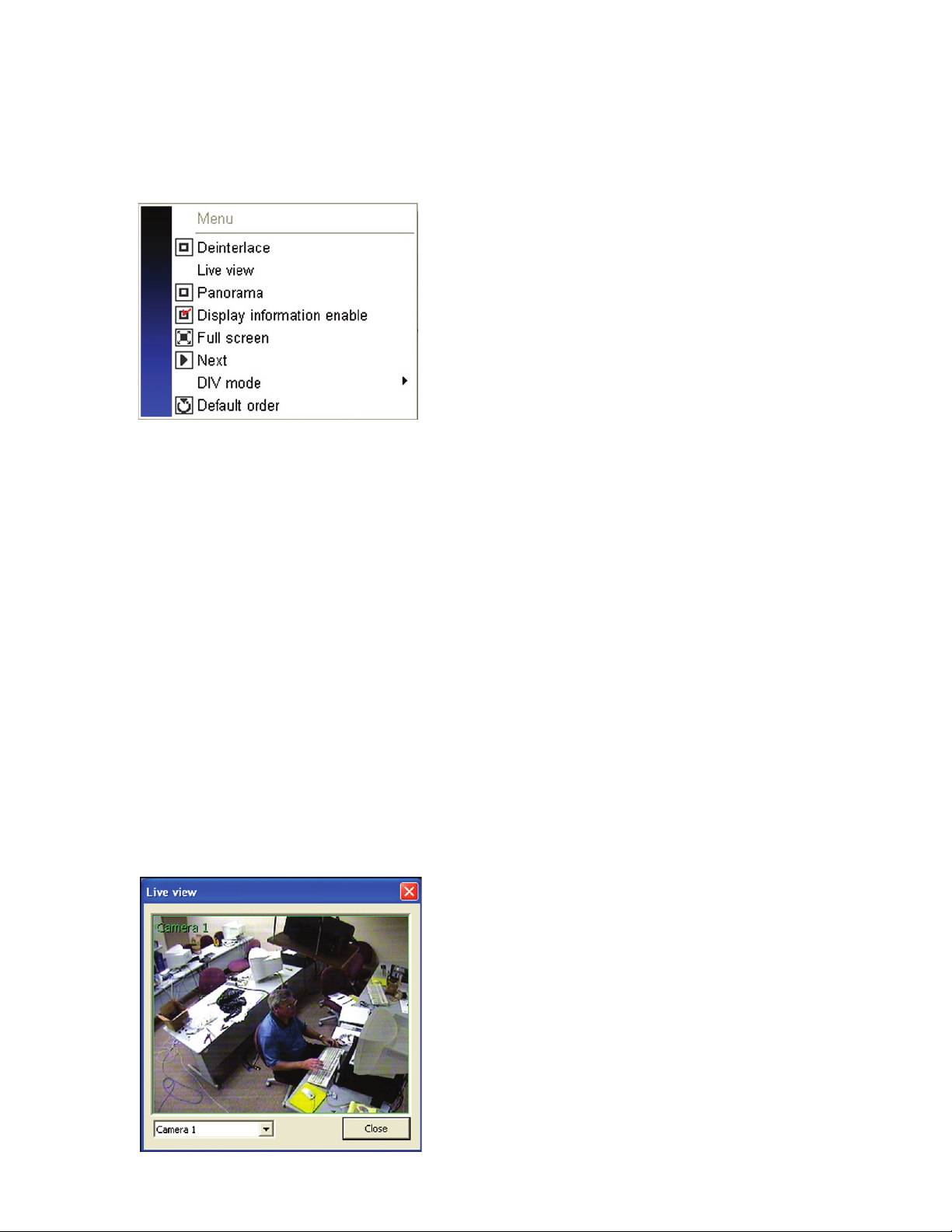
68
e search screen popup menu allows the user to deinterlace video, watch one channel of live video, view
one channel in panorama view, turn on or off on screen display, go full screen, change the screen layout and
revert the screen layout to the default view.
Deinterlace
NTSC video is a sequence of images called frames.
W
hen these single frames are played back the image is
perceived as flickering. Engineers found that displaying the same frame in two parts (called fields), meaning
one field is for the odd lines (1, 3, 5, 7...) and one field for the even lines (2, 4, 6, 8...) and doubling the rate
(60 1/2 fps and 50 1/2 fps) avoids flicker thanks to screen remembrance. This process is called interlacing.
When a CRT refresh rate is fast enough this works fine. But with the introduction of LCD monitors some
moni
tor
s’
display cannot interlace but must draw the entire screen each time, the video must be deinterlaced
before it can be displayed.
Clicking this function will deinterlace your video showing a better picture. When
the playback is in deinterlace mode there will be a red check mark in the
deinterlace box.
Live View
is feature allows the user to view a single channel of live video while in the playback screen. To view a
channel of video select the channel to view (it will be highlighted with a red border indicating it is the se-
lected channel). Right click the viewing screen to bring up the popup menu and click live view. e live view
window will popup onscreen displaying the selected channel.
To view a different channel click on the
camera menu box and select the channel.
To close the Live view screen, click the
close button
Page 77
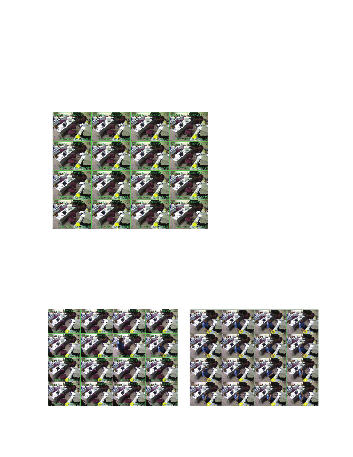
69
Panorama
Panorama view allows for the detail viewing of each frame of video for a single camera channel. is allows
the user to see the motion in a frame by frame environment. To enter panorama mode, select the channel for
viewing by clicking in the frame, then right click to bring up the pop up menu and click panorama. When in
panorama mode there will be a red check mark beside panorama in the pop up window.
To stop viewing in panorama mode, double click an image on screen or right click to bring up the pop up
menu and click panorama removing the red check mark.
Display Information Enable
is feature allows the user to control whether or not the display information is shown on screen. To display
information click this feature from the pop up menu. A red check mark will appear when enabled. To turn
off, click display information enable removing the red check mark.
display information on
display information o
ff
Page 78
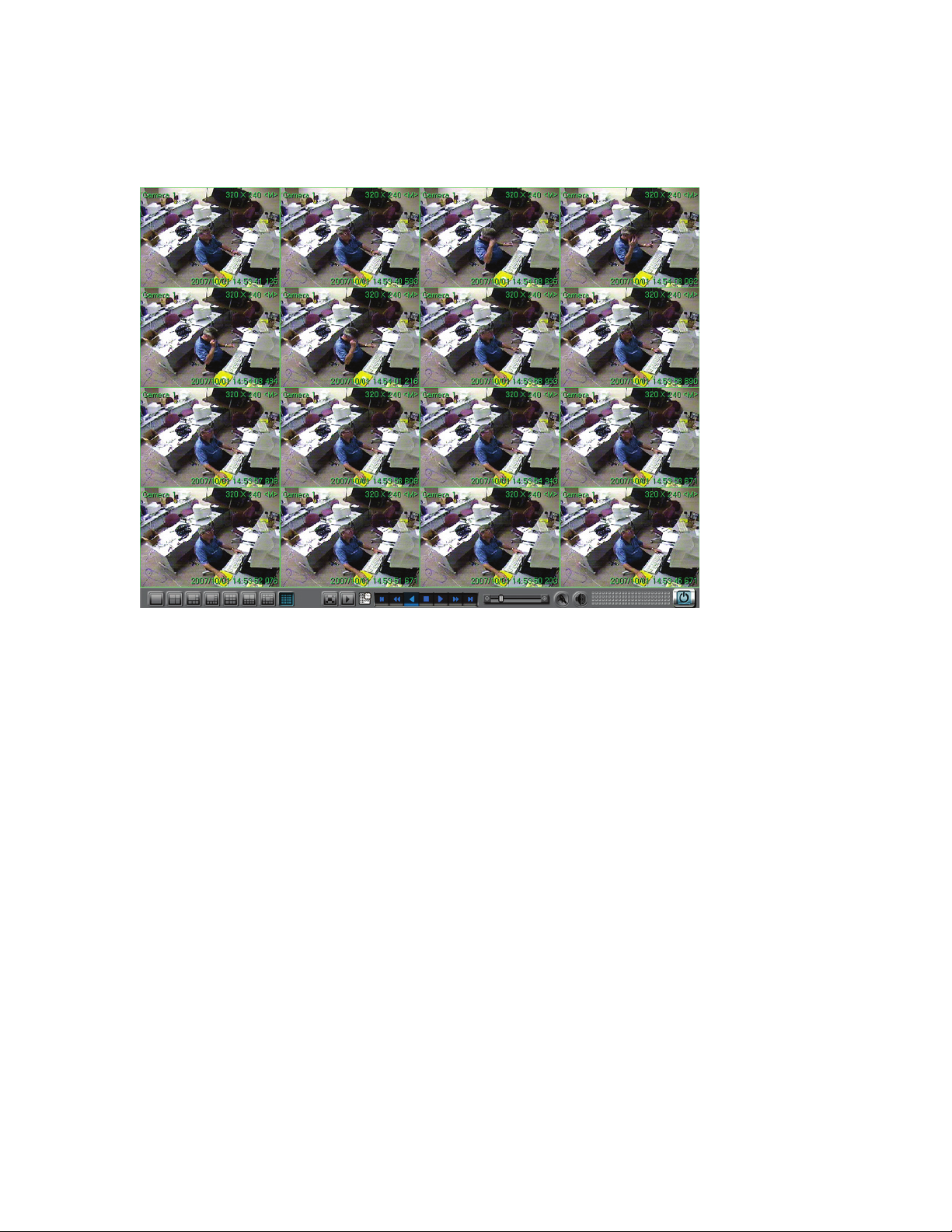
70
Full screen
Clicking this feature will place the screen in full screen mode. is will allow for a bigger viewing area. When
the system is in full screen mode the menu changes to normal screen. Click this to revert to normal viewing
screen.
full screen mode enabled
Next
When in single camera mode clicking next will move the screen to the next camera view in sequence.
Div Mode
Division mode allows the user to change the screen division.
Default Order
Clicking this button removes any modified screen back to the default screen order. If the user has moved
screens by clicking and dragging using this feature will return the screen back to its original order.
Page 79
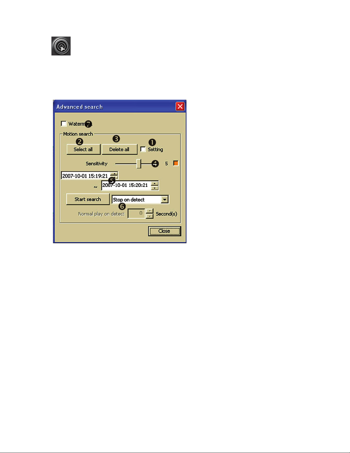
71
Advance Search
e advance search feature allows the user to search one or more channels of video using motion detection.
e image below is the setup menu for the advance search feature.
Basic Feature of Advance Search
Setting check box:
Check this box to display motion area grid on screen. No check mark means motion area
selection grid will not display on screen. It is sometimes useful to not display the motion grid
area during search.
Select All:
Use the select all button to select the entire camera area as the motion search grid. Select the
camera to place the grid area, select the sensitivity, and then click select all.
De
lete All:
Use the delete all button to delete the entire motion search grid of a camera. To use, select the
camera to remove the motion area grid from and click the delete all button.
Page 80
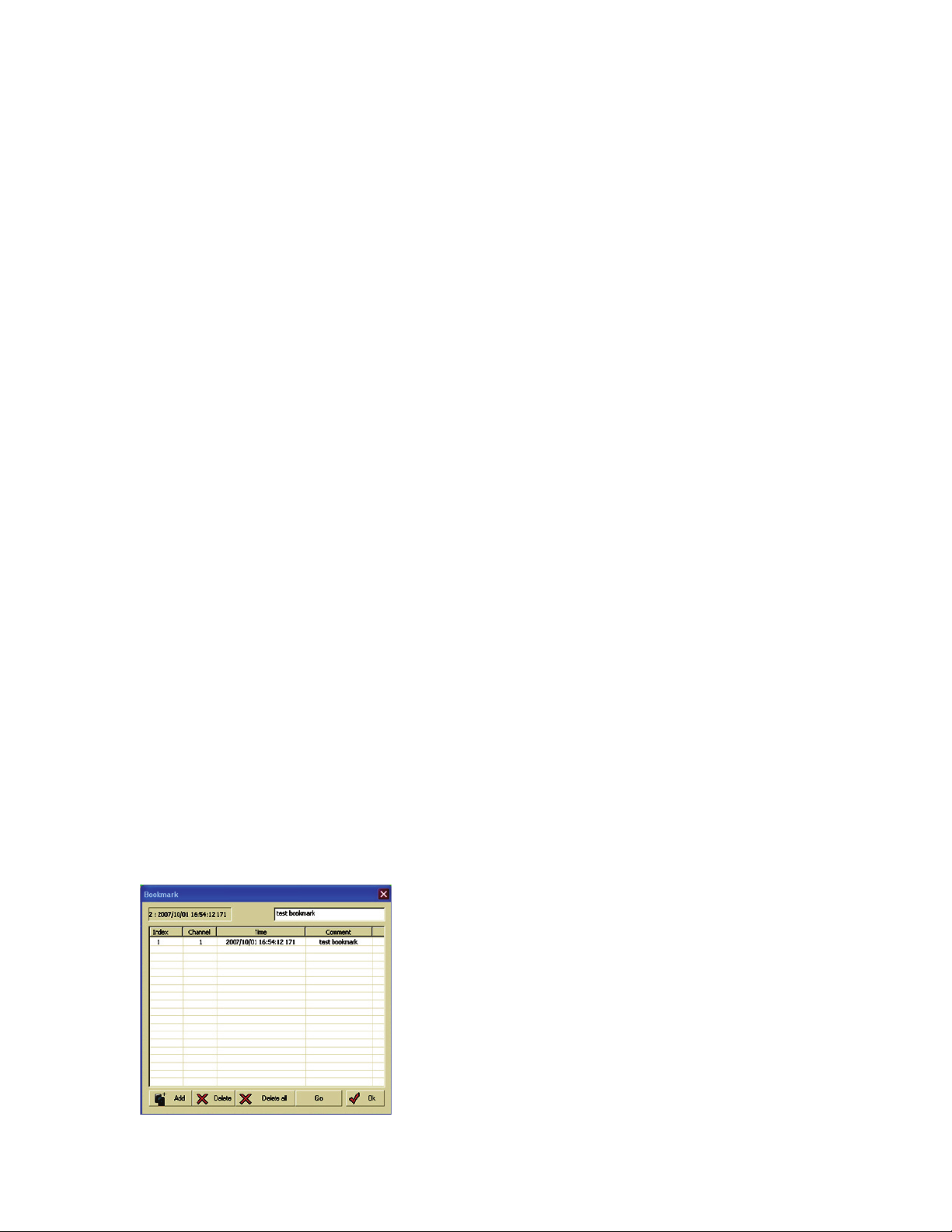
72
Motion Detection sensitivity Control
Use this feature to set the sensitivity (how much pixel change must occur) before motion is
detected. Moving the slide bar to the le is less sensitive, to the right is more sensitive. Moving
the slide bar to the le edge will allow for deleting selected areas. e selecting grid is color
coded with green being least sensitive and red being the most sensitive. e sensitivity control
bar must be set before using the mouse to select the grid area.
Date & Time
Selection
Use the top box to set the date and time to begin your motion search. Use the lower box to
designate the date and time to stop the motion search.
Motion Search Mode Setup
ere are three modes to use when using advance search:
• Stop on detect - System will stop search when motion is detected. Click start search
button to resume search.
• Normal play on detect - System will begin to play at normal speed for the designated
number of seconds before resuming the search at fast speed. Set the number of
seconds to play at normal speed in the normal play on detect seconds box below the
mode selection box.
• Non stop search - e system will continue to search the video without stopping.
Automatic bookmark will be turned on when in this mode. To see the times
video motion was detected click the bookmark function button.
Watermark
is function allows the user to display the watermark during the search to validate that the
video has not been changed or manipulated.
Using the Bookmark Feature with Advance Search
e bookmark feature can be used to mark video detected by the advance motion search. is way the video
can be retrieved easily for viewing or backing up. Using the bookmark feature is different depending on the
type of search mode used. If Stop on detect or Normal play on detect is used the user must manually select
the bookmark feature from the search screen menu. If the user selects Nonstop detect then the bookmark
feature will automatically add a bookmark at the start of every motion detected.
Bookmark will automatically be added when using
advance search in the non stop on detect mode.
Page 81
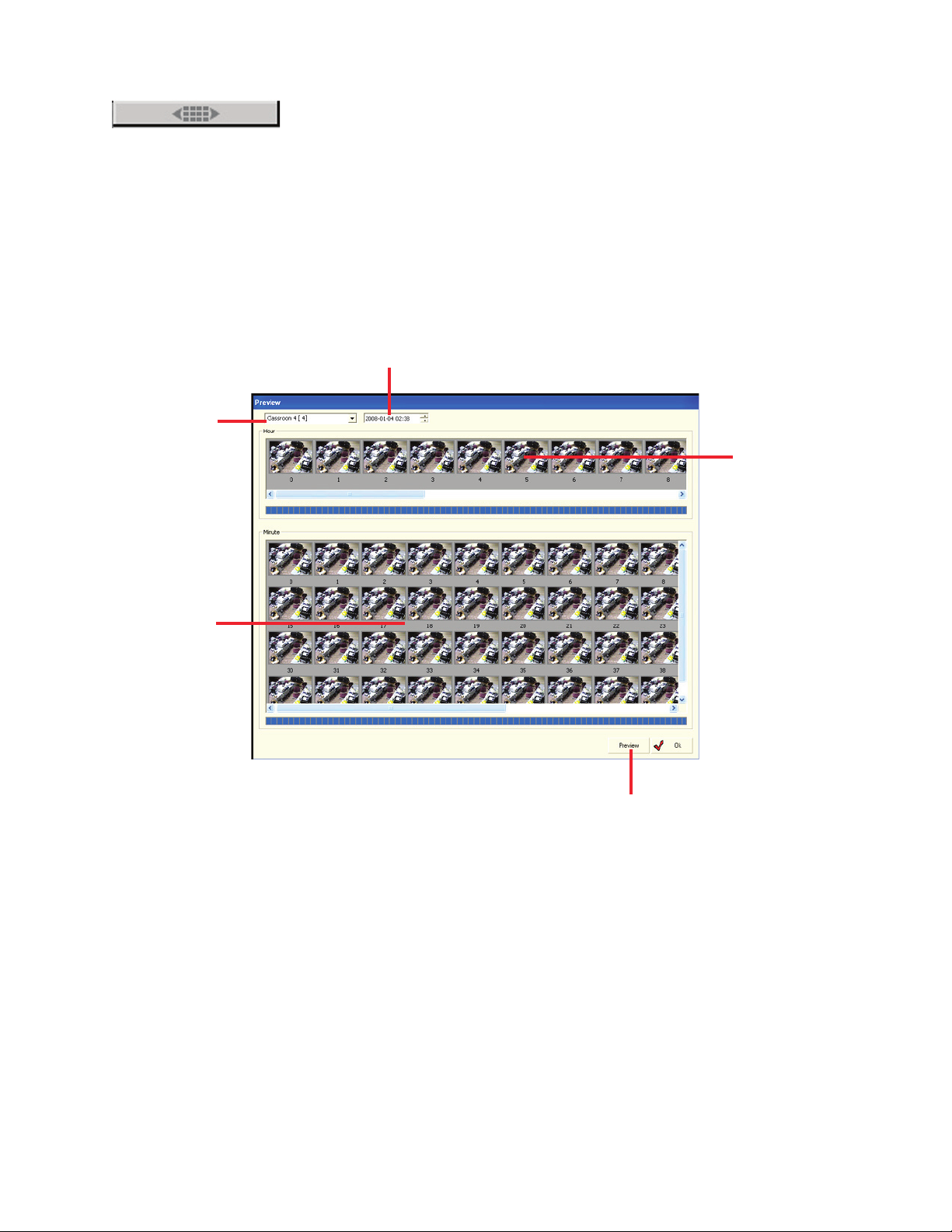
73
umbnail
Preview
umbnail preview feature displays a single camera showing 24 hours in one view. It allows for the selection
of an hour and displays 60 images from the beginning of recorded video of every minute for the selected
hour. is provides a way to view recorded video for a selected camera quickly. To enter thumbnail preview
function, select a camera and click the thumbnail preview button.
Camera selection
Date selection
S
elect hour to display
Minutes displayed
for selected hour
Click preview button aer selecting a new cam-
era or date to refresh screen.
Double click an image to go back to the search screen and begin playback from selected date and time.
Page 82
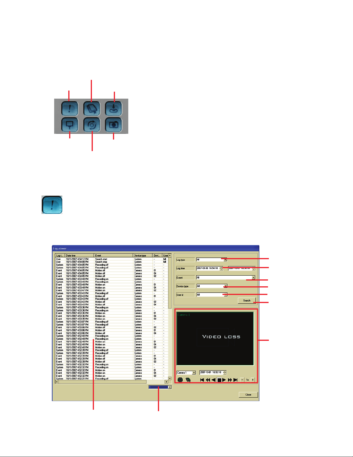
74
e following options are available from the search screen menu buttons. For detailed information on
the functions of each option, please refer to each option’s detailed section.
Event
Bookmark
Backup
Color control
E
xternal search
Snapshot
Event Search
Use event search to view a database of all event information that occurred during system operation.
Select log
Beginning and end
search date & time
Select event
Select device type
Select User
B
egin search
View video for event
Number of pages of events
Events
Page 83
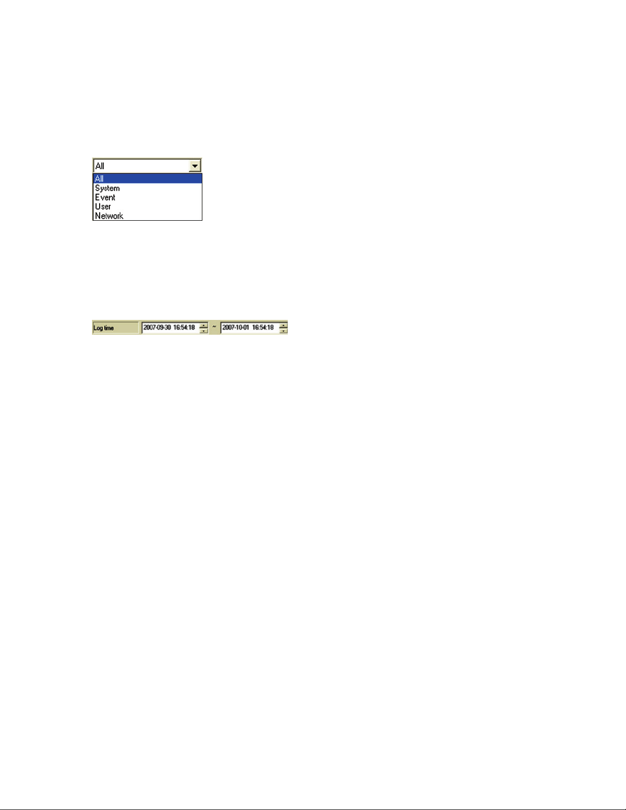
75
Select log
Use select log to narrow the event search to a specific type of log. e choices are:
• All
• System
• Event
• User
• Network
Select log dropdown box
Select Log Time
Set the beginning and end time to search the event database.
Select Event
is allows the user to narrow the search to a specific event. e list of events that are recorded to the data-
base are:
• All • Email notification success • Program update
• Alarm sound off • Emap execute • Quick search start
• Alarm sound on • Emergency recording off • Quick search stop
• Audio sound off • Emergency recording on • Recording data add
• Audio sound on • Environment setup change • Recording data overwritten
•Automatically logoff • Environment setup close • Recording fail: HDD error
• Backup start • Environment setup open • Recording fail: checksum error
• Backup stop • FPS setup changed • Recording fail: read error
• Camera setup change • HDD full • Recording fail: write error
• Client connect • Login • Recording off
• Client disconnect • Logoff • Recording on
• Email notification fail: • Motion off • Relay off: User
SMTP user authentication fail • Motion on • Relay off: system
• Email notification fail: • Network setup change • Relay on: system
Unknown error • Old record data delete • Relay on: user
• Email notification fail: • Pantilt control control • Schedule setup change
Connection failed • Pantilt control start • Search start
• Email notification fail: • Pantilt control stop • Search stop
cannot connect to mail server • Pantilt setup change • Sensor off
• Email notification fail: • Popup video channel • Sensor on
no user info • Program terminate • Sensor/Relay setup change
Page 84
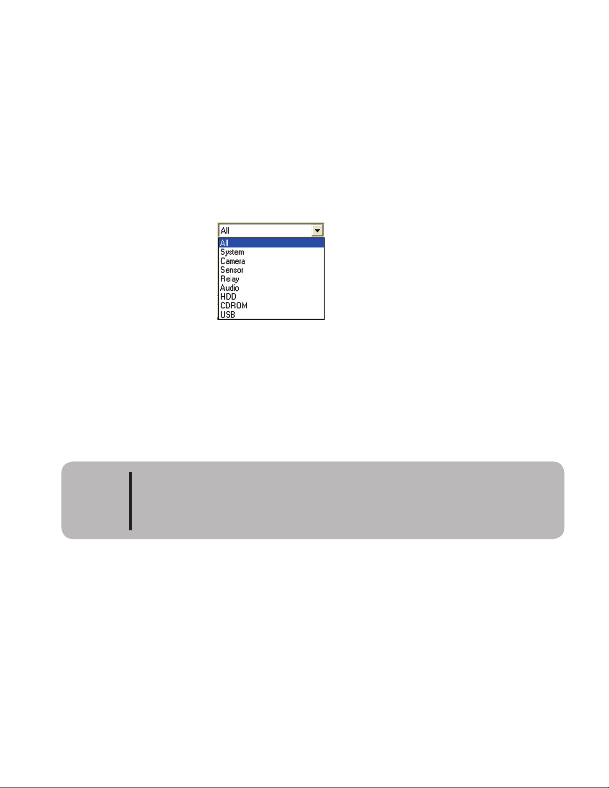
76
• Server start • System start • User account changed
• Server stop • System time synchronized • User factory default
• Snapshot execute • Twoway audio off • Video Blind
• System Abnormal shutdown • Twoway audio on • Video loss
• System reboot • UPS notification: power loss • Video on
• System setup change • UPS notification: power recover • Web server start
• System shutdown • UPS notification: system shutdown • Web server stop
Device type
Allows the user to choose the exact device to view logs for. e different devices are:
• System
• Camera
• Sensor
• Relay
• Audio
• CDROM
• USB
User ID
Allows the search to be narrowed by using a user ID setup in the system.
e log event data is stored for a maximum period of 60 days. Aer 60 days it will be
automatically deleted.
CAUTION
Page 85
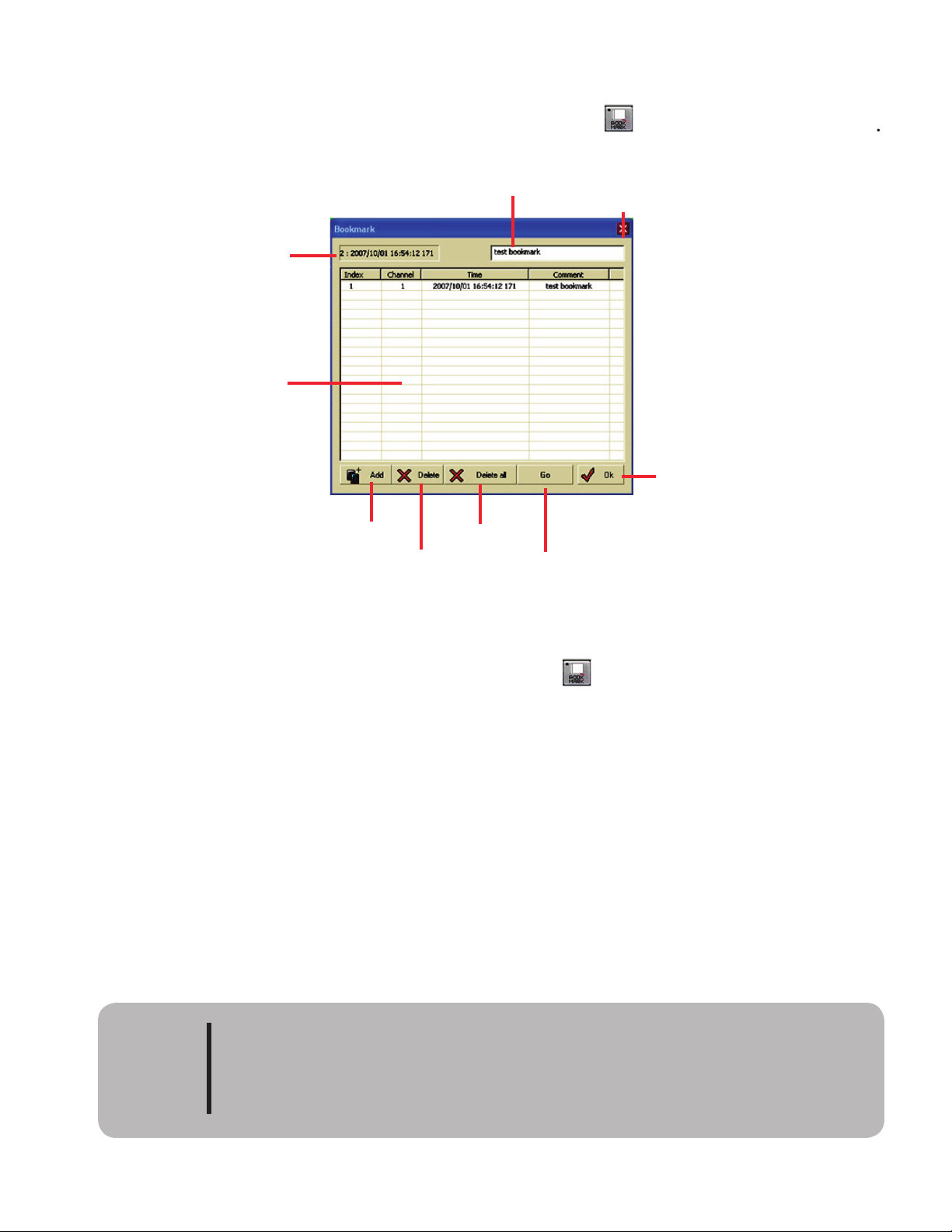
77
Bookmark is used to mark video that you want to quickly return to without having to search. To set or re-
trieve a bookmark from the playback screen, click the bookmark icon
To add a bookmark, first find the video to be bookmarked in the search screen, then click the pause button.
Next, enter the bookmark screen by clicking the bookmark icon
the currently paused search screen date and time in the window to the le of the anno tation note field. Type
a note as to the reason for creating the bookmark in the comment field, then click ADD. e new bookmark
is added to the list.
To play a bookmark, highlight the bookmark you want to review and click GO. e system begins playing
back the selected date and time. Double clicking the selected book mark will also start the system playing the
selected date and time. To return to the play back screen, click the OK button or the X at the top right of the
bookmark menu.
close
Bookmark comment
add book mark
delete book mark
go to selected
bookmark image
exit bookmark screen
current image date/time to
add bookmark
registered bookmark list
delete
all
NOTE: Registering a bookmark only records a date, time and camera to begin play-
it should be backed up as soon as possible. If the reg is tered video is no longer avail-
able in the HDD due to overwriting, it cannot be played back. In this case the book-
mark should be deleted
CAUTION
Page 86
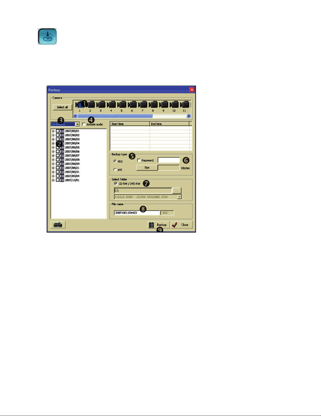
78
Backup
e backup feature allows the user to backup recorded video for archiving. Video can be backed up in one of
three formats - VD2, AVI or BMP snapshot files. e VD2 and AVI file backups can be done by clicking the
backup button. e snapshot backup is done by clicking the snapshot button which will be covered later in
this chapter. e image below shows the main backup screen for VD2 and AVI file backup.
Camera selection - Select the cameras to back up.
Recorded video - Lists the recorded video for the camera or cameras selected and method recorded.
Mode recorded - Use this to select mode by which the video was recorded. Options are:
All
Continuous
Sensor
Motion
Include audio - Check this box to include recorded audio.
Recording type - Select the type of output file for the backup. Options are:
VD2 - Same format that the original file was recorded in. Includes playback viewer.
AVI - Multimedia video format. Must use third party viewer to view video.
Password - Enter a password for video backup security.
Select backup drive - Select the drive and backup folder for writing the backup to.
Backup name - name the backup
Backup button - Aer all selections have been made click backup button to start backup.
Page 87
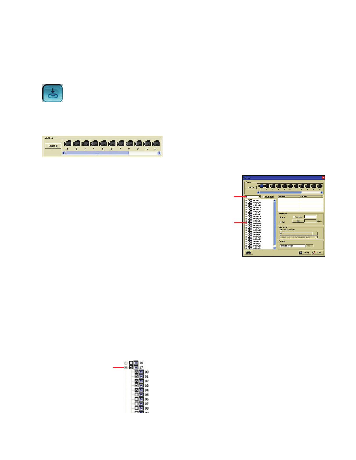
79
Making a VD2 Backup
Making a VD2 file backup will keep the video files in their native file format. Because these files use a pro-
prietary algorithm they can only be read with the simple viewer soware. When making a backup the simple
viewer soware will be saved on the backup disk along with the video files. e instructions below show how
to do a backup in the VD2 format.
CTL key and click the camera icon. To select all cameras click the all button. You may also click and drag to
Highlight multiple cameras.
All
Continuous
Motion
Sensor
When selecting the recording mode the video
selection grid will only display video that was
recorded in the selected mode. If you are not
sure how the video was recorded select the
all mode. is will display all recorded video
regardless of the mode in which it was recorded.
can be further expanded into hours and the hours can be expanded to minutes. Click the + beside the day
to expand the day into hours and click the + beside a particular hour to expand the list to minutes. If there
are missing days, hours or minutes that means there is no recorded video for that time. To select video
place a check mark in the day (selects all video for that day), hour (selects all video within that hour) or
minute. Please note that when selecting a minute there might not be a complete minute of recorded video
there may be as little as 1 second of video.
Select recording
mode
video selection
grid
Click the + to expand the
hour to minutes.
Page 88
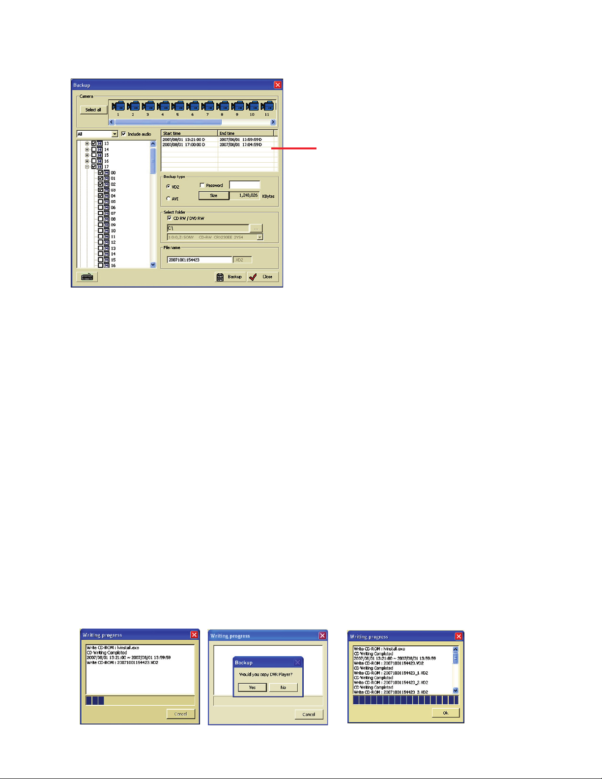
80
to be backed up is selected.
convert Kilobytes to Megabytes divide by 1024. By checking the size, you can tell if the backup will fit the
drive that will hold the backup. If you are using a CD-RW or DVD-RW drive the system will allow multiple
disk backup. When the first disk is full it will ask for the next disk.
backup. Please use caution in using this feature, if the password is lost the video will not be recoverable.
drive select the check box CD-RW and the video will be written to the CD. Please use caution if writing to
drive C. is drive contains the operating system which must have available drive space to function
properly. If this drive is filled up with backup video the DVR will not function properly.
ask if you want to copy the backup player. Click yes and a copy of Simple View will be written to the disk. If
multiple disks are required for backup, the system will prompt for the next disk. When using a CD-RW
drive the system can write to either a CD-R or CD-RW disk.
Selected video chosen for backup
Page 89
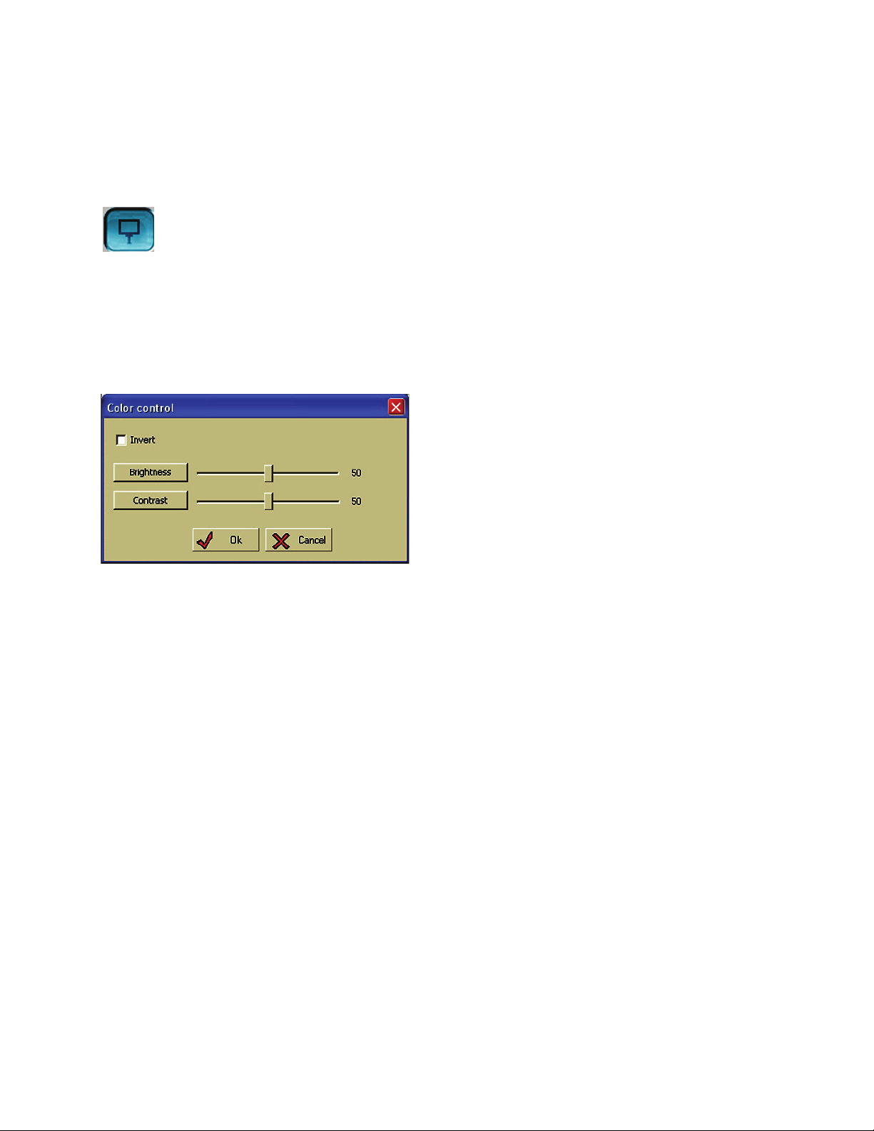
81
Making an AVI File Backup
Making an AVI file backup is the same as making a VD2 file backup with the following exceptions. When
selecting the type of backup click AVI. e password option and size option will disappear as they are not
available when making an AVI backup.
Color Control
e DVR system lets the user control the brightness, contrast or invert the search video. Use the picture con-
trols shown below to control these features. To invert the selected channel, click the invert check box. When
in invert mode there will be a check mark in the box, click it again to close invert mode. Move the slider bar
le or right to control the brightness or contrast of the selected picture. To change the control back to the
default level click the brightness or contrast button.
Page 90
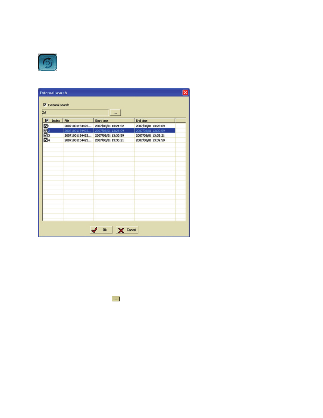
82
External Search
External search allows the user to playback video from an external source such as a CD. To enter this func-
tion click the external search button.
Refer to the following steps for using the external search feature
• Place your external media in the CD-RW drive.
• Click the external search check box.
• Click the eclipse button
and select the location of your backup video.
• When the backup data appears place a check mark in the index check box field to choose all video.
• Click OK and the external video will begin playback.
Page 91
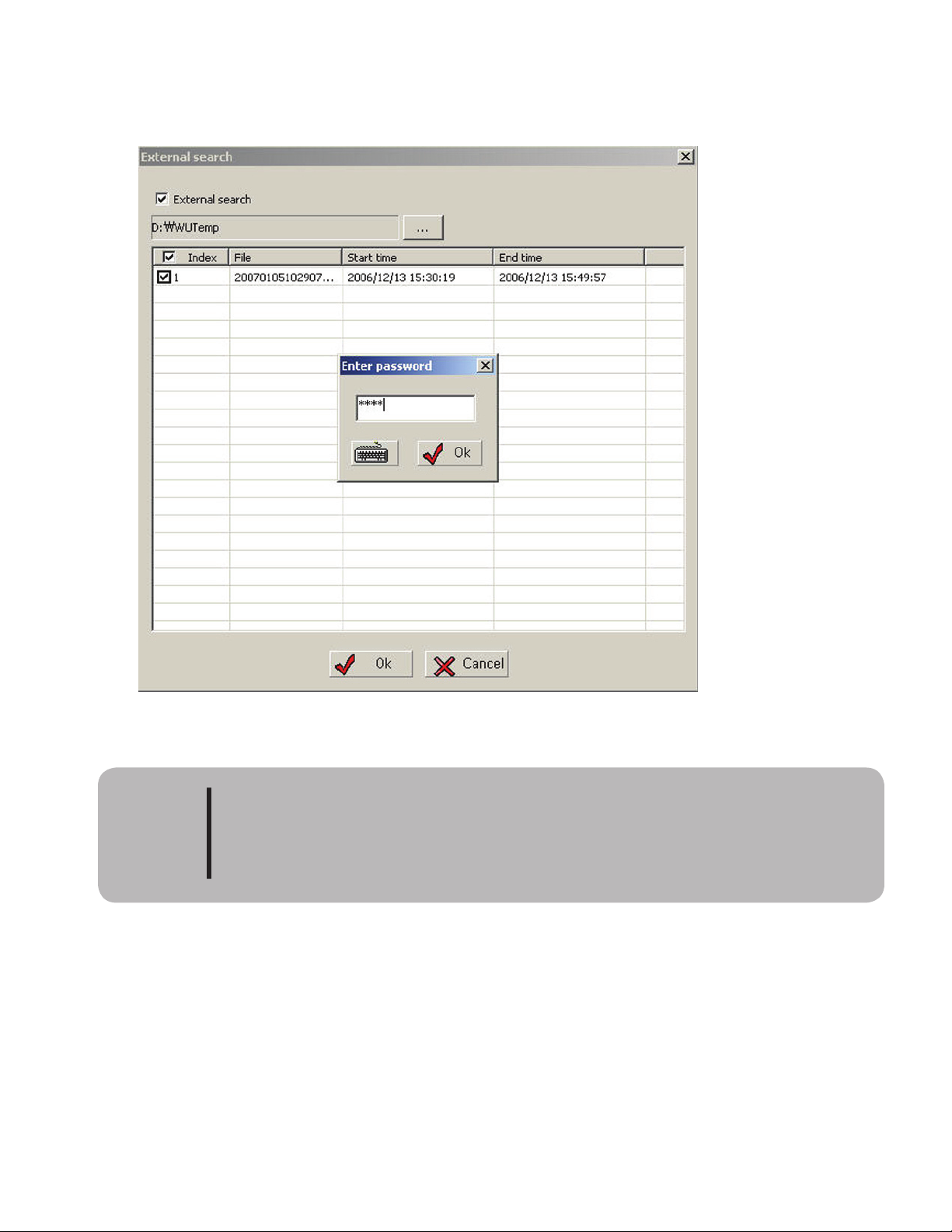
83
If a password was used when making a VB2 file backup, when clicking the OK button the password input
window will appear. Enter the password to begin playing the external video. If the incorrect password is en-
tered, video cannot be viewed.
NOTE:
If user forgets password the factory cannot recover lost pass-
words.
CAUTION
Page 92
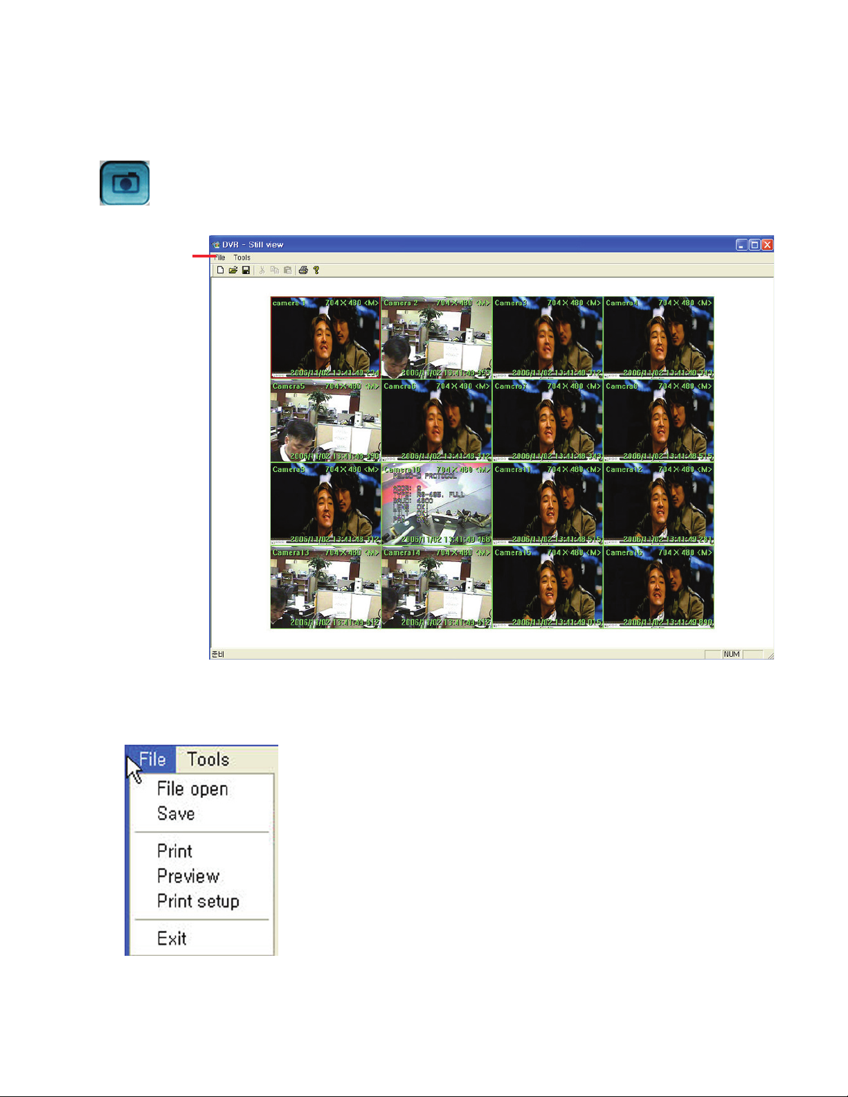
84
Snapshot
e snapshot feature is used to take a screen shot of the current video. is still shot can then be adjusted
with the color and contrast controls. e file can then be saved or printed if there is a printer installed and
connected to the DVR. To start snapshot, click the snapshot button.
File and tools menu
Features of the file menu
• Open File - Opens a saved file as a snapshot (JPG, BMP)
• Save - Save the current snapshot.
• Print - Print the current snapshot. Must have printer installed.
• Preview - Preview the snapshot before printing.
• Print setup - Call the printer setup feature for you printer.
• Exit - Close the snapshot screen
Page 93
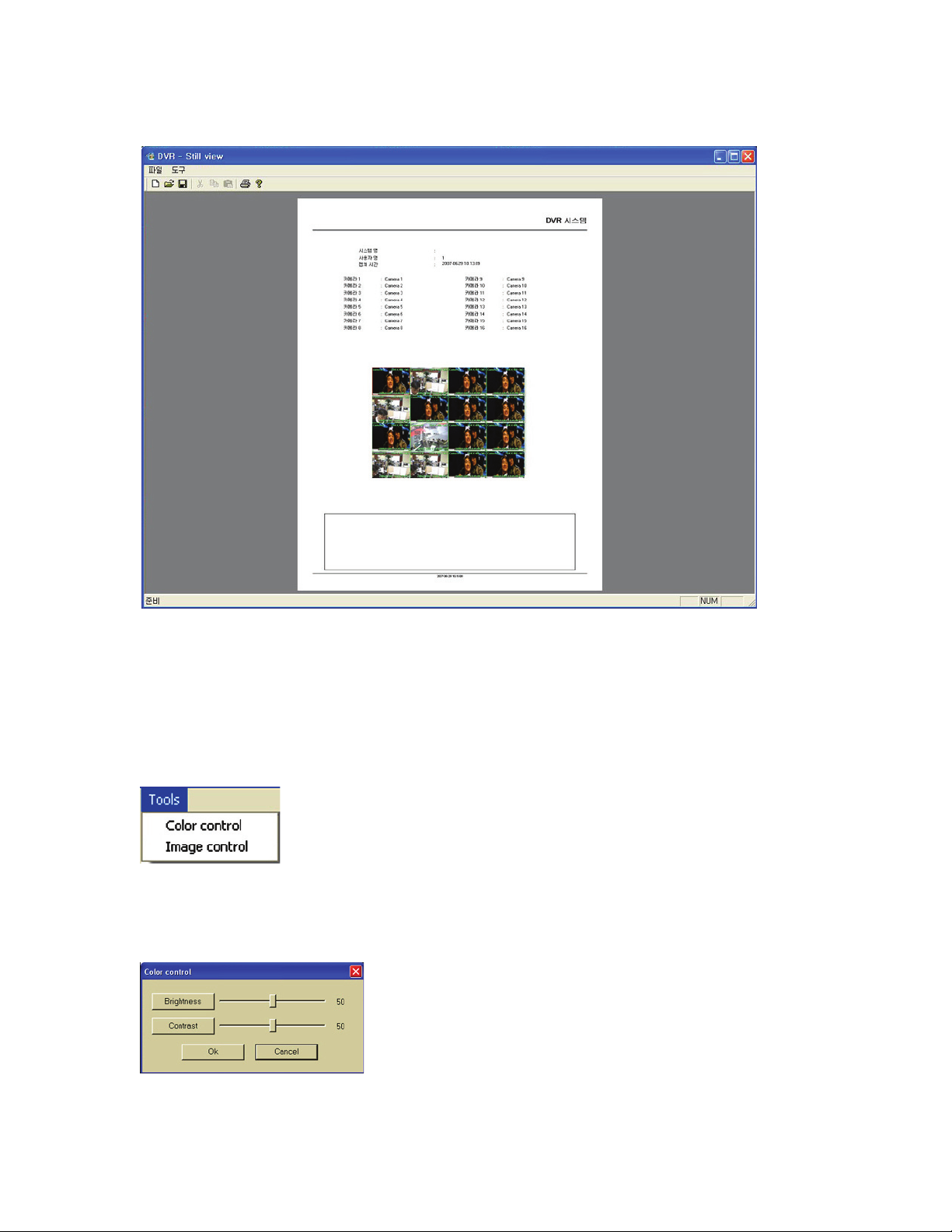
85
Print Preview
If snapshot is printed, the system name, user name, capture time and camera name information are printed
with the snapshot. See image below for example of print preview.
Features of the Tool menu.
• Color control - allows the user to adjust the brightness and contrast.
• Image control - allows the user to control the image size, mirror, flip
or invert the image.
Page 94
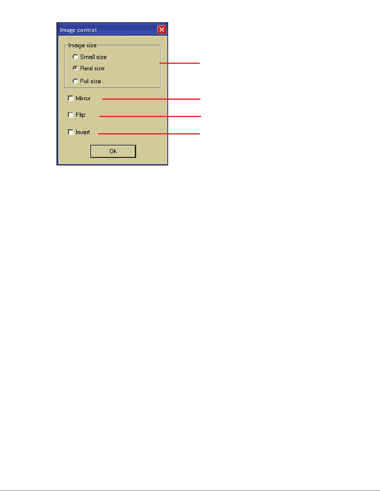
86
Change the size of the image.
Reverse the screen horizontally (le to right)
Reverse the screen vertically (top to bottom).
Reverse the screen colors (white to black)
Page 95

E-Map Function
Page 96
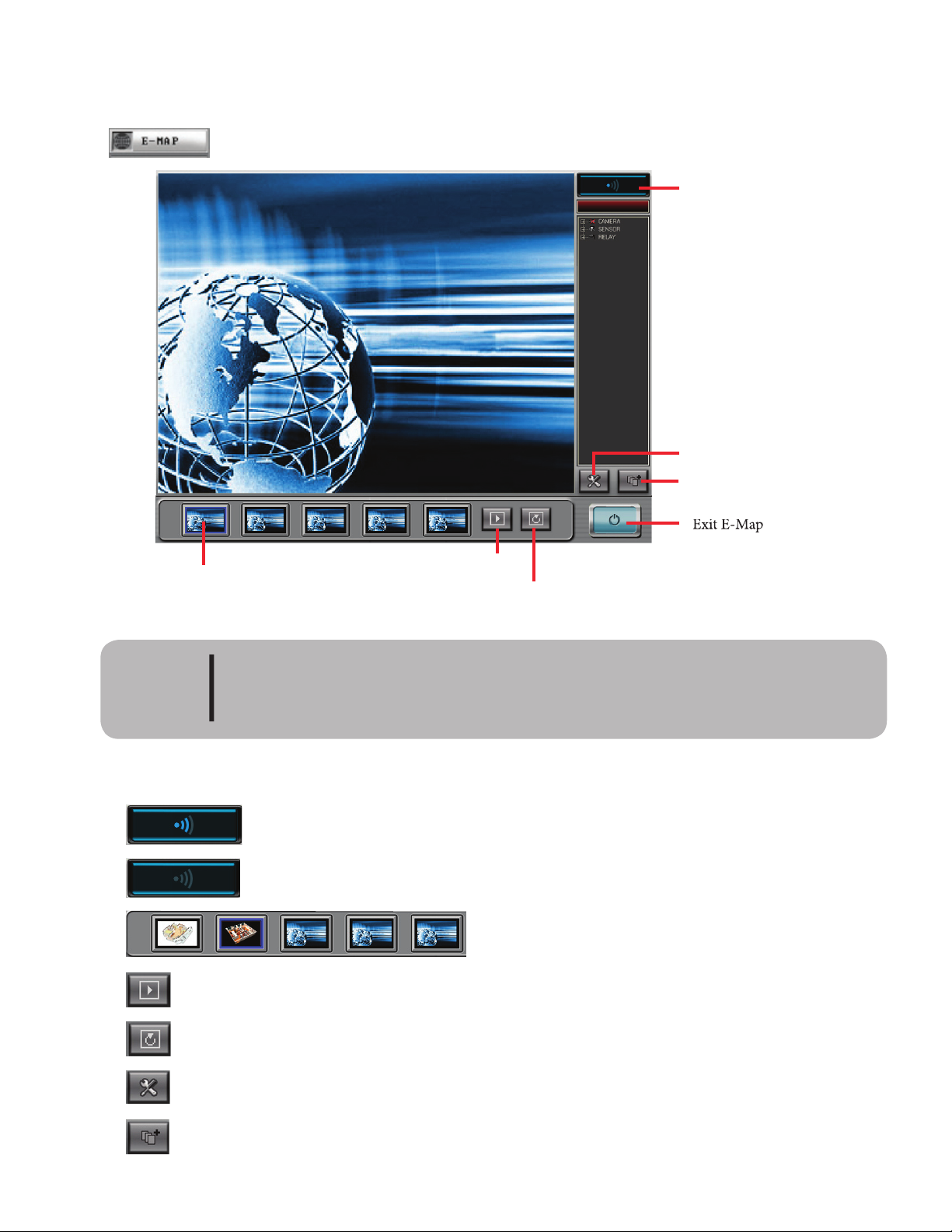
88
e E-Map is a function that allows the user to see the physical location of cameras, sensors and relays on a
graphical display. e system allows the user to use a supplied image or to create his own custom image. To
enter E-Map, Click the E-map button on the Live screen (Main Screen).
Exit E-Map
Map
sequence setup
Save
custom map
Next
Auto sequence
Map thumbnail
Active
/ Edit button
manager can use E-Map if they have been granted the E-Map rights by the adminis-
CAUTION
E-Map in active mode - Icon will flash on and off. In this mode you can use E-Map
to view cameras, sensors and relays.
E-Map in edit mode - Icon will not flash but be turned off. In this mode you can
setup E-Map images, add cameras, sensors, and relays to the image.
Map thumbnails - displays a thumbnail of the map for
quick reference
Next button - Change the screen to the next map in sequence.
Auto sequence button - Click this and the map will automatically sequence between the
maps in the order setup in map sequence screen.
Map sequence setup button - Click to enter the setup screen for map sequence.
Add custom map button - Click to save a custom map to the system for use with E-Map.
Page 97
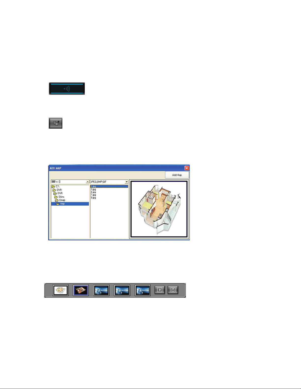
89
Setting Up E-Map
Before the user can use the E-Map function it must first be setup. To use the setup features E-Map must be
in edit mode. E-Map has two modes - active mode and edit mode. When in active mode the active/edit icon
will flash off and on. When in edit mode the icon will be dull and not flash. If the user tries to edit E-Map
while in active mode they will receive the following message: “only available in edit mode”. To setup E-Map
follow the steps below.
• Place E-Map in edit mode by clicking the active icon.
• Add Map - Add any custom maps that the user has created. e basic size of the map is 640 x 480
and can be a BMP, JPG or GIF image file. If a file size larger than 640 x 480 is used the map will be
reduced to this basic size. To add a map click the add map button.
• From the add map window navigate to the drive and directory that contain the custom map and
click add map button. e map will be saved in the DVR’s default directory for maps (see image
below).
• Place Map - Select the maps to display the cameras, sensors and relays. E-Map allows up to five
maps to be displayed. To place a map select a map thumbnail and double click it.
double click a thumbnail to bring up the select map window
Page 98
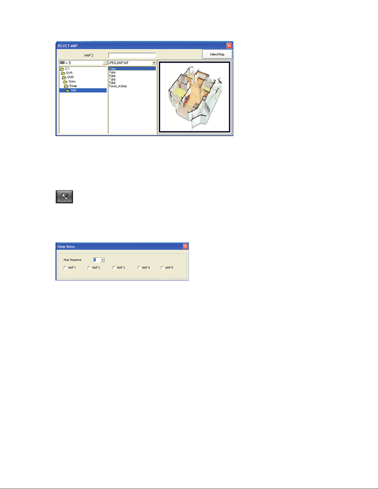
90
• e select map window will appear (see image below).
• Highlight an image and it will display in the sample window. Aer highlighting the image click the
Select map button and the map will be placed in that position. Continue to add the desired number
of maps (maximun of 5).
• Set map sequencing - click the map sequencing button to bring up the map sequence window.
• Select the maps to include in the auto sequence by placing a check mark in the box beside the map
number. en set the number of seconds (1 to 60) to pause before moving to the next map (see
image below).
• Select the map to place the camera, sensor or relay by clicking on its thumbnail. e picture
will be displayed on screen.
• Select a camera, sensor or relay from the list on the right side of the screen by clicking on the
name - it will then be highlighted in blue.
• Right click the selected camera, sensor or relay. e mouse will change from a hand to an
arrow. Move the arrow to the desired location on the map and click the mouse. is will
place the camera, sensor or relay icon on the map. If you need to move the icon simply select
it again from the list by right clicking and place it again in the new location. A camera,
sensor or relay can be placed only one time. If you select a camera, sensor or relay for
placement a second time it will remove the icon from its original location to the new
location.
• Finish placing the icons on all the maps to complete the E-Map setup.
• Click the active / edit mode button to place E-Map in active mode.
Page 99
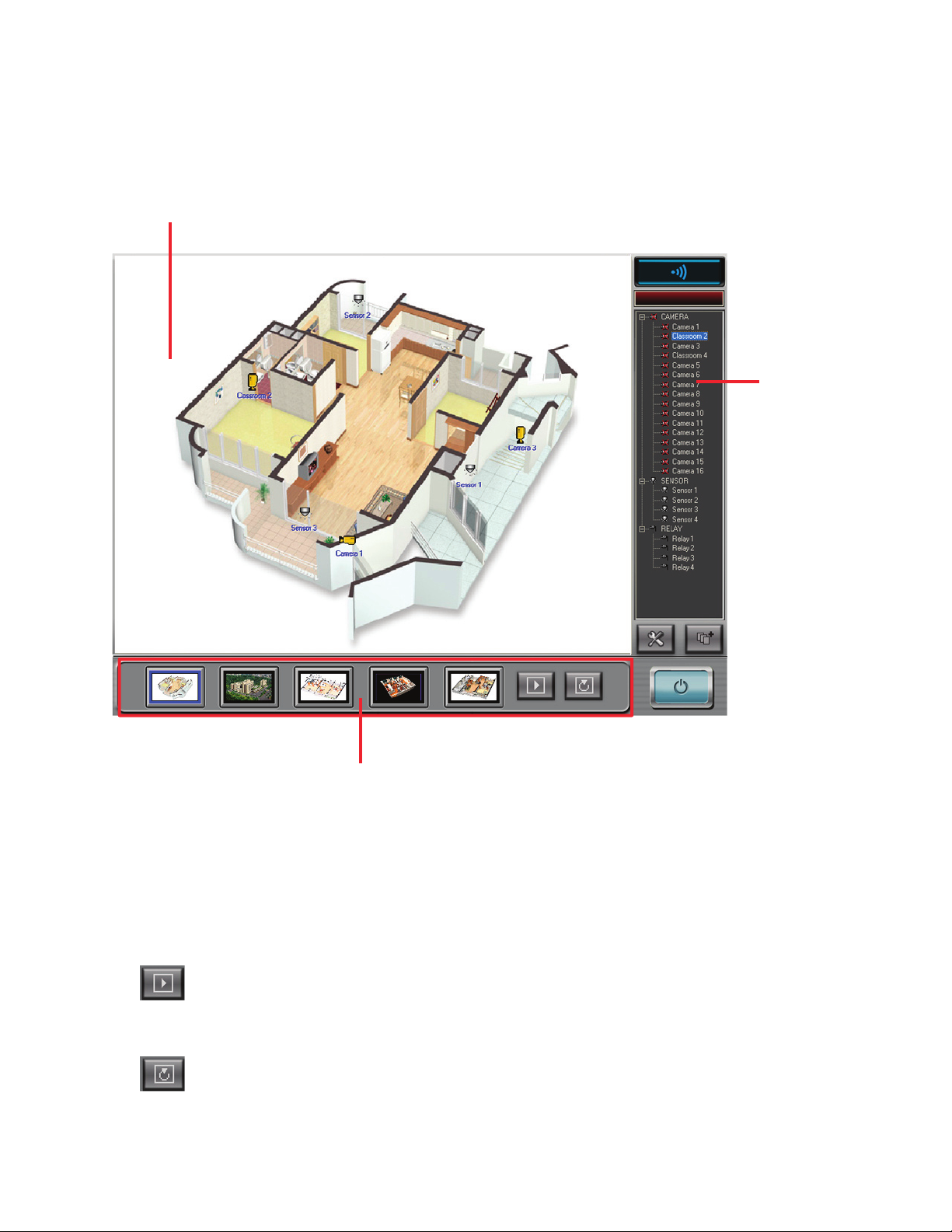
91
Using E-Map
Aer E-Map has been setup and been placed in active mode E-Map is ready for use. e E-Map screen
consists of three main sections - map screen, map thumbnail, and camera, sensor and relay tree. e image
below shows these sections.
Map section
Camera, sensor,
relay tree.
umbnail section
• Map Screen - Display screen for the 5 maps available in E-Map.
• Camera, Sensor, Relay Tree - A tree listing of all camera, sensors and relays available in the DVR.
• umbnail Section - A thumbnail of the 5 different maps available in E-Map.
Next button - Changes the screen to the next map in sequence.
Auto Sequence button - Will automatically rotate between screens: turns blue when on.
Page 100
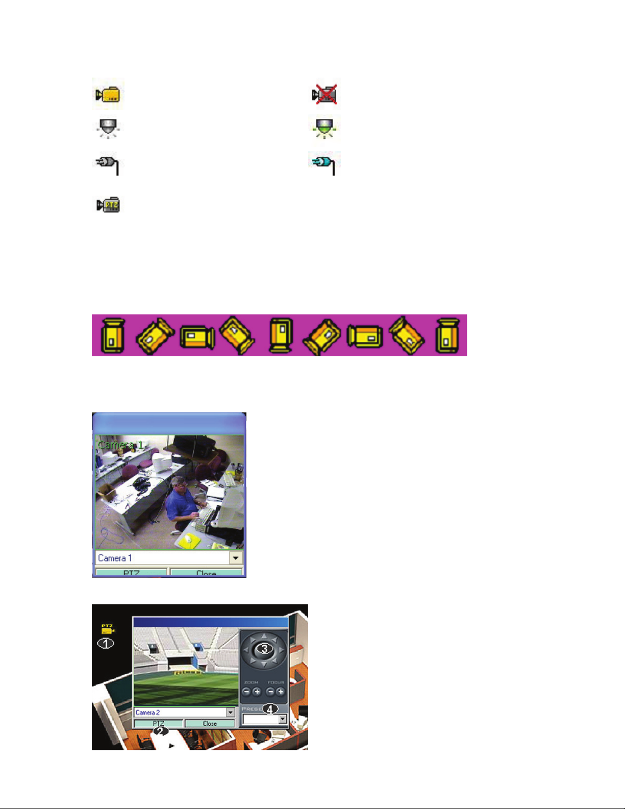
92
e icons for the camera sensor and relay will change appearance during an event. Below are the different
icons and the corresponding event.
Camera icon
Camera disconnected icon
Sensor icon
Sensor activated icon
Relay icon
Relay activated icon
PTZ camera icon
Viewing a camera from an E-Map camera icon
Double click a camera icon that is not in a disconnected state
to bring up the live view of that camera. e user is able to view
other cameras by selecting the camera drop down menu on the
button of the camera picture. If the camera is a PTZ camera, click
the PTZ button to control the PTZ function. To close the live view
click the close button at the bottom right of the live screen.
2). Click the PTZ button to display the PTZ controls.
3). Use PTZ controls to move PTZ camera.
4). Use call button to call presets.
Camera Angle Adjustment mode
Aer placing the camera on the map click the camera to change the angle. Continue clicking until desired
angle is achieved.
 Loading...