

Crest Audio UMA 4300 Owner's Manual

UMA™4300
Professional Series
Installation Power
Amplifer
Owner’s Manual
1

ENGLISH
UMA™ 4300
Professional Installation Power Amplifier
The UMA 4300 is a high quality, commercial grade analog audio mixer/amplifier. Designed for flexibility in application, this mixer/
amp represents the latest, state-of-the-art technology in analog and class-D circuit design. Powerful, yet easy to use, the new UMA
series delivers amazing sonic performance. Low-noise design and features applicable to “real-world” situations make these units ideal
for audio applications where a compact, powered mixer with multiple input and output capabilities are required.
This manual was written to provide as much information as possible for your new Crest Audio Professional Series Installation Power
Amplifier. It is our sincere desire that you enjoy your purchase. We feel that the best way to fully enjoy any purchase is to have an
in-depth understanding of the product’s features, functionality, and performance characteristics. We hope that this manual, along
with the manuals of our other products, will provide this. If you require additional information that this manual does not provide,
please let us know. We are continuously looking for better ways to provide information about our products, and your input is always
appreciated. If you require additional information not provided in this manual‚ please let us know or check out our website at:
Web site: http://peaveycommercialaudio.com/products.cfm/cr/:
Email: techserve@crestaudio.com
We are continuously looking for better ways to provide information about our products and your input is always appreciated.
UMA™ 4300 Features:
• Efficient 300 Watt class-D power amplifier
• 4 electronically balanced mic/line Inputs
• 2 Inputs feature selectable dual-RCA, summing
connectors for Auxiliary sources
• Discrete-transistor, variable-gain, channel preamps for
consistent front panel level control.
• Channel 1 Priority/Muting system with variable
threshold adjustment and mute indication
• External switch input for “Mute All” control with
indication
• Bass and treble equalization controls
• Preamp output and power amp input loop for external
processing equipment or auxiliary output
• Electronically balanced line output with level control
and mix or channel 4 source selector
• Amplifier signal indicator
• ACL ™ (Automatic Clip Limiting) circuitry with
indicator
• 25 Volt, 70 Volt, and 100 Volt outputs
• Power ON indicator
• Line Voltage Selector switch for 100-120 VAC or
220-240 VAC 50/60 Hz operation
• Optional rack mounting with included rack ears
• 4 Ohm direct output
Applications:
• Presentation rooms • Board rooms • Courtrooms • Auditoriums • Lecture halls • Meeting rooms • Convention centers
• Paging systems • Background music • Retail spaces • Restaurants
2
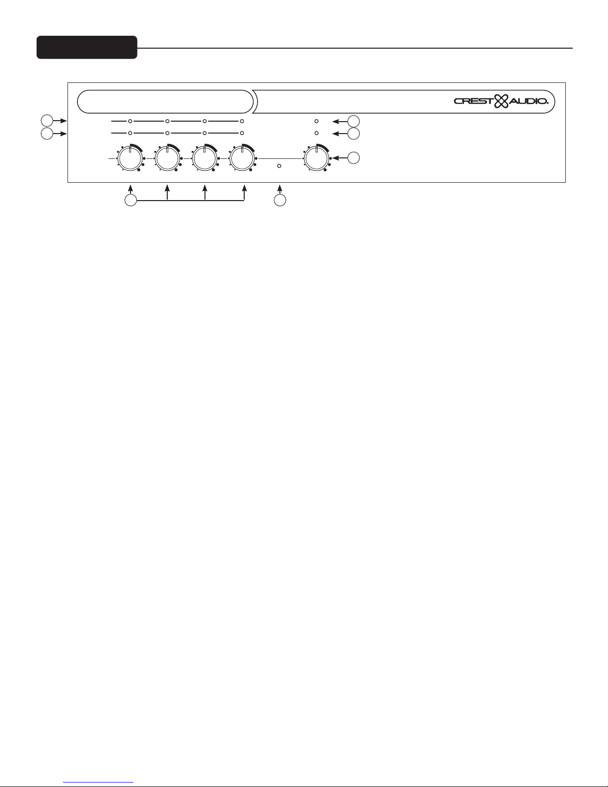
Front Panel
UMA 4300
TM
2
3 4
PEAK/MUTE
SIGNAL
LEVEL
ACL/MUTE
1 2 3 4 MASTER
min max min max min max min max min max
1 7
SIGNAL
POWER
5
6
PROFESSIONAL SERIES INSTALLATION POWER AMPLIFIER
(1) Input Channel Level Controls
These rotary controls set the channel signal level sent to the mix bus. It is best set in the 12:00 to 2:00 range as indicated
on the front panel. The preamp gain control should then be adjusted for proper operating level.
(2) Input Channel Peak/Mute indicators
These red LEDs perform a dual purpose of indicating that the corresponding channel is muted and when the input signal
is too high and distortion can occur. To correct the problem, lower the corresponding channel gain control.
(3) Input Signal Indicator (SIG)
These LEDs illuminate green to indicate signal presence on the corresponding input.
(4) Output Signal Indicator (SIG)
These LEDs illuminate green to indicate signal presence to the mixer output master.
(5) ACL/Mute Indicator
This LED will illuminate red when the signal in the power amplifier reaches the point where the ACL circuit (Automatic
Clip limiter) engages. The ACL circuit reduces the gain automatically when necessary to prevent amplifier clipping. It
will also illuminate red when a switch closure is present on the Mute All input causing all signals through the amplifier to
be muted.
(6) Master level control
The master control sets the overall signal level of the system. It is best set in the 12:00 to 2:00 range as indicated on the
front panel.
(7) Power Indicator
This LED illuminates when powered and active.
3
Rear Panel
9
POWER
ON
50/60Hz
65 WA TTS
Consumo de energia 65Wh
8
10 14 1816 22 22
FUSE
FUSE
FUSE
FUSE
FUSE
100 -120V
T6.3AL/250V
220- 240V
T3.15AL/250V
FOR 100 -120V OPERATION,
FUSE MUST BE CHANGED
TO T6.3AL/250V
100 -120V
220- 240V
FOR 220-240V OPERATION,
FUSE MUST BE CHANGED
TO T3.15AL/250V
11
OUTPUTS
100V
70V
25V
COM
4 Ohm
CLASS 2 WIRING
LINK
LINE
OUTPUT
SELECT
MIX
CH. 4
(summed) (summed)
EQ
MIN MAX MIN MAX MIN MAX MIN MAX MIN MAX OFF MAX MIN MAX
HIGH
LOW
MIN
MAX
12 13 15 17 19 19 19 1925
(8) IEC Inlet connector
This receptacle is for the IEC line cord (included) that provides AC power to the unit.
(9) Power Switch
This rocker switch applies mains power to the unit.
(10) Fuse Holder
RCA SELECT
4 3
21
4 3
20
TM
UMA 4300
A PRODUCT OF CREST AUDIO INC.
5022 Hwy 493
MERIDIAN, MS 39305
DESIGNED AND ENGINEERED IN U.S.A.
PHANTOM
POWER
+48V
GAIN GAIN
INPUTS
MADE IN CHINA
MUTE
THRESHOLD
2 1
PHANTOM
POWER
+48V
20 23
MUTE
ALL
_
+
G+_G+_G+_G+_GGAMP IN PRE OUT
2424
20
INPUT
The fuse is located within the cap of the fuse holder. If the fuse fails, IT MUST BE REPLACED WITH THE SAME TYPE
AND VALUE NOTED ON THE BACK OF THE UNITS FOR THE SELECTED LINE VOLTAGE IN ORDER TO AVOID
DAMAGE TO THE EQUIPMENT AND TO PREVENT VOIDING THE WARRANTY. If the amp repeatedly blows the fuse,
it should be taken to a qualified service center for repair.
WARNING: The fuse should only be replaced when the power cord has been disconnected from its power source!
(11) Line Voltage Selector Switch
The line voltage select should be checked and set to match the mains voltage before connecting and operating this unit. The
UMA 4300 can be operated at 100V-120 VAC or 220-240 VAC 50/60 Hz.
(12) Outputs
A direct output and transformer outputs are provided to allow proper interface between the amplifier and the loudspeaker
system. Connect the loudspeaker system to the appropriate output connector and the COM terminal. Connections for 4
Ohm, 25 Volt, 70 Volt and 100 Volt systems are available.
(13) Processing Insert Connector
The preamplifier output and power amplifier input and ground are brought to this connector allowing processing such as an
external equalizer to be inserted. The link switch (see below) bypasses this connection.
(14) Link switch
The link switch, by default connects the preamp output to the power amplifier input.
(15) Line Output
The balanced line output with level control can be used to extend the mixer to other power amplifiers, provide a monitor
output, or send background music to a phone system etc. The output source is selectable (see output source selector below)
(16) Output Source Selector
The signal sent to the line output can be selected to be either the main mix or the input 4 signal.
4
 Loading...