

Page 1
PRELIMINARY
INTRODUCTION
Congratulations on your purchase of the CREST 2.4 On Board Train Engineer Wireless
Control System
2.4 TRAIN ENGINEER INSTRUCTION MANUAL NS Page 1 of 39
Page 2

Contents
2.4 TRAIN ENGINEER INSTRUCTION MANUAL NS Page 2 of 39
Page 3
GENERAL INFORMATION
PAGE
1. Features 5
2. System Components 6
3. Transmitter Diagram and Components 7
4. System Components Diagram Receiver, Code Set Switch, Aux Harness“ ” 8
5. Operation Overview 9
6. Functions for System Components 10
7. Code Set Switch 10
8. Auxiliary Wire Harness Table 10
9. Smoke Control Board 10
10. Receiver Adapter 11
11. Receiver Installation 11
12. Transmitter Installation 11
13. Charging Transmitter Batteries 11
14. Power On/Of 12
15. <<T T>> Cab Control– 12
16. Stop/Enter 12
17. Arrow Functions 12
18. Menu 12
19. All Stop 12
20. Number & Letter 12
21. Number Key 1-6 12
22. Number Key # 12
23. Number Key 0 / all stop 12
24. View MU Locomotives 12
25. Charger 13
26. Cab Power 13
27. Battery Power 13
28. Setup a Single Locomotive SU“ ” 14
29. Setup a Single Locomotive SU“ ” 15
30. Setup a Single Locomotive SU“ ” 16
31. Operation- Run a SU With the Transmitter‘ ’ 17
32. Setup Multiple Locomotives MU ‘ ’ 18
33. Setup Multiple Locomotives MU‘ ’ 19
34. View Individual Locomotives 20
35. Locomotive Running in the Opposite Direction 20
2.4 TRAIN ENGINEER INSTRUCTION MANUAL NS Page 3 of 39
Page 4
36. Smoke Unit Control 21
37. Sound Unit Control 21
38. Changing From [SU] to [MU] TO [MU] 22
39. Changing From [SU] to [MU] TO [MU] 23
40. Main Set Up 24
41. Assign Functions 24
42. Link Address 24
43. RX Type 24
44. Name 24
45. Road No 24
46. Momentum 24
47. Delay 24
48. Motor 25
49. Head DIR 25
50. Headlight ON/OFF 25
51. Top Speed 25
52. Start Speed 25
53. Aux Function Setup 26
54. Aux Function Mode 26
55. Basic 26
56. Extended 26
57. Latch 26
58. Momentary 26
59. Linking/Link Ok 27
60. Quick Menu List 28
61. Aux Function Table 28
62. Sound & Auxiliary Table 29
63. Link Ok / No Link 30
64. Overload 30
65. Overheat 30
66. Usage of Cab 30
67. Add MU/SU Cab 31
68. Single Unit SU‘ ’ 31
69. Multiple Units MU‘ ’ 31
70. Copy Loco Before /After– 32
71. System Configure 33
72. Power OFF 33
2.4 TRAIN ENGINEER INSTRUCTION MANUAL NS Page 4 of 39
Page 5
73. Brightness 33
74. Contrast 33
75. Key Tone 33
76. Radio Configure 34
77. RF-Channel 34
78. Group ID 34
79. My Memo 34
80. Reset Memory 35
81. Quick Menu List 35
82. Aux Function 35
83. Aux Function Mode Output 36
84. Step Speed 36
85. A ->Z Name Search 37
86. About System 37
87. Receiver Harness Adapter Installation 38
88. Powering the On Board Receiver 38
89. Connecting the Power Wires 38
90. Isolate the Motor Wires 38
91. Connecting the Headlights 38
92. Securing the On Board Receiver 38
93. Plug in the Receiver to the Wire Harness Socket 38
94.
95.
1. FEATURES
Adjustable Momentum Control
Adjustable Forward & Reverse Delay
Adjustable Top Speed
Adjustable Start Speed
All Stop
Adjustable Back Light
Copy Locomotive Settings
Can Supply 5amps of Power
Direction Control Headlight
2.4 TRAIN ENGINEER INSTRUCTION MANUAL NS Page 5 of 39
Page 6

Direction Control Motor
Function Mode
Individualized Locomotive Setting
Large LCD Screen
LCD Backlit Graphic Screen
Multiple Group Codes
Memory For Up To 50 Trains
Over Load Protection
Outdoors Range Exceeds 400 Feet
Polarity Protection
Peak Loads That Can Go to 8 amps
Range of 300 Indoors ‘
Single Unit SU ‘ ’
Six Auxiliary Outputs on the Receiver
Multi Units MUed 6 locomotive‘ ’
Smoke Control
Sixteen Function Accessories
1. SYSTEM COMPONENTS
The CREST 2.4 On Board Wireless Control System consists of 6 components,
a. 2.4 Transmitter
b. Receiver
c. Auxiliary wire harness
d. Code set switch
e. Smoke control board
f. Wire harness.
2.4 TRAIN ENGINEER INSTRUCTION MANUAL NS Page 6 of 39
Page 7
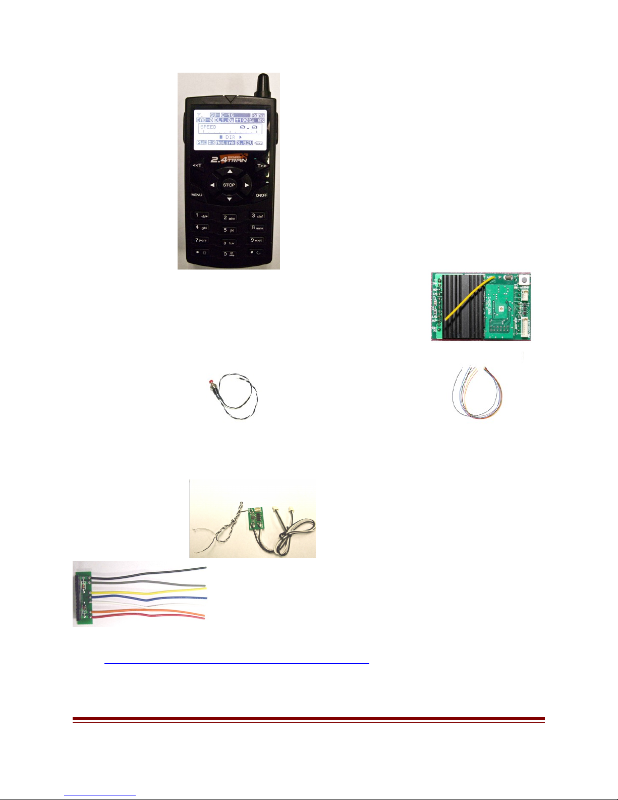
2.4 Transmitter Receiver
Code Set Switch Auxiliary Wire Harness
Smoke Control Wire Harness
2. 1] TRANSMITTER DIAGRAM AND COMPONENTS
2.4 TRAIN ENGINEER INSTRUCTION MANUAL NS Page 7 of 39
Page 8
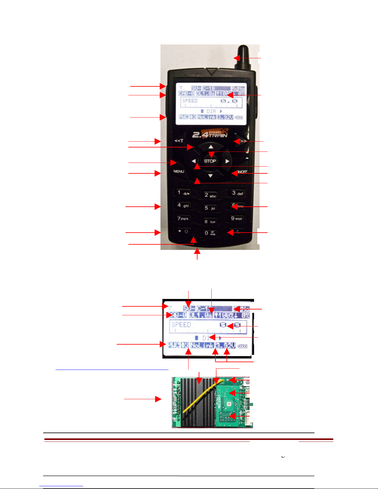
Antenna Signal
Antenna
Cab # Active Locomotive" “
PWC / Linear Power
Choose Cab Number
Fast Speed Up Arrow “ ”
Reverse Direction Left Arrow “
Menu Button
Number & Letter Key
View MU Locomotives
All Stop/
Reset button
Start Speed
Choose Cab Number
Forward Direction Right Arrow “ “
Stop / Enter
On / Off
Slow Speed Bottom Arrow “ ”
Number & Letter Key
# Key Delete
Quick Menu /aux
functions
Charger Jack
Loco Name
[SU] [MU] Locomotive Name
[DL] Delay
Step Speed
3. SYSTEM COMPONENTS DIAGRAMS
Heat Sink
2] Receiver
Link Status
Top Speed
Loco Road Number
Locomotive Speed
Locomotive Direction
Battery Voltage
Antenna Red LED
Push Button Link ‘ ’
Code Set Switch
Socket 3 Pin
Aux Socket 7 Pin
Plug to 3 Pin Aux
Socket
2.4 TRAIN ENGINEER INSTRUCTION MANUAL NS Page 8 of 39
Page 9
Code Set
3] Code Set
Button
Switch
Common
4] Auxiliary Wire
Harness
Plug to Seven Pin Aux
Socket
To Aux Functions
5] Smoke Control
Board
Connect to any Aux
wire
Connect to Aux Common
wire Black’ ’
6] wire Harness
Plug the cable from
loco. Power input
Plug to smoke units Art
29311
Power Input
Motor
Light
Common
Light
Motor
Power Input
Before you start working with the Train Engineer Revolution there are a few concepts that
you need to understand.
2.4 TRAIN ENGINEER INSTRUCTION MANUAL NS Page 9 of 39
Operation Overview
Page 10

The transmitter and receivers in your locomotives are designed to communicate and exchange
information about the way you want your trains to operate. In order to establish a link
between them you need to set up options in the transmitter. These include settings like the
locomotive’s name and road number, the top speed that you want it to achieve, the rate at
which you want it to accelerate and how long you want it to delay when the direction is
changed. Once these parameters are set the link between the units is finalized by a process
called “linking”. Once the transmitter and a locomotive’s receiver are bound together they are
set to communicate and run your train.
The second concept has to do with the Cab number that is associated with each locomotive.
The Cab numbers range from CAB-0 through CAB-49. Once you link a locomotive you must
select the Cab number that it will run under. This allows you to easily move between as many
as 50 locomotives while operating. The Cab number is also used to identify groups of
locomotives that you might want to run in a consist ‘MU’. Locomotives can be operated
independently or grouped for multiple unit operation. CAB-0, CAB-1 and CAB-2 might be
used to operate three different locomotives while CAB-3 can be used to operate those same
three locomotives in a consist ‘MU’. Changing between single unit (SU) operation and
multiple unit (MU) operation is as simple as selecting a Cab number.
Once you have an opportunity to experience the process used to operate trains with the TE
Revolution I think you will find that Aristo Craft has found an elegant solution to what can be
a complex problem
Functions for System Components
4. CODE SET SWITCH
a. Mount the code set switch so you can get access to program your locomotive.
b. Press the code set switch and hold down to link the transmitter and receiver.
2.4 TRAIN ENGINEER INSTRUCTION MANUAL NS Page 10 of 39
Page 11
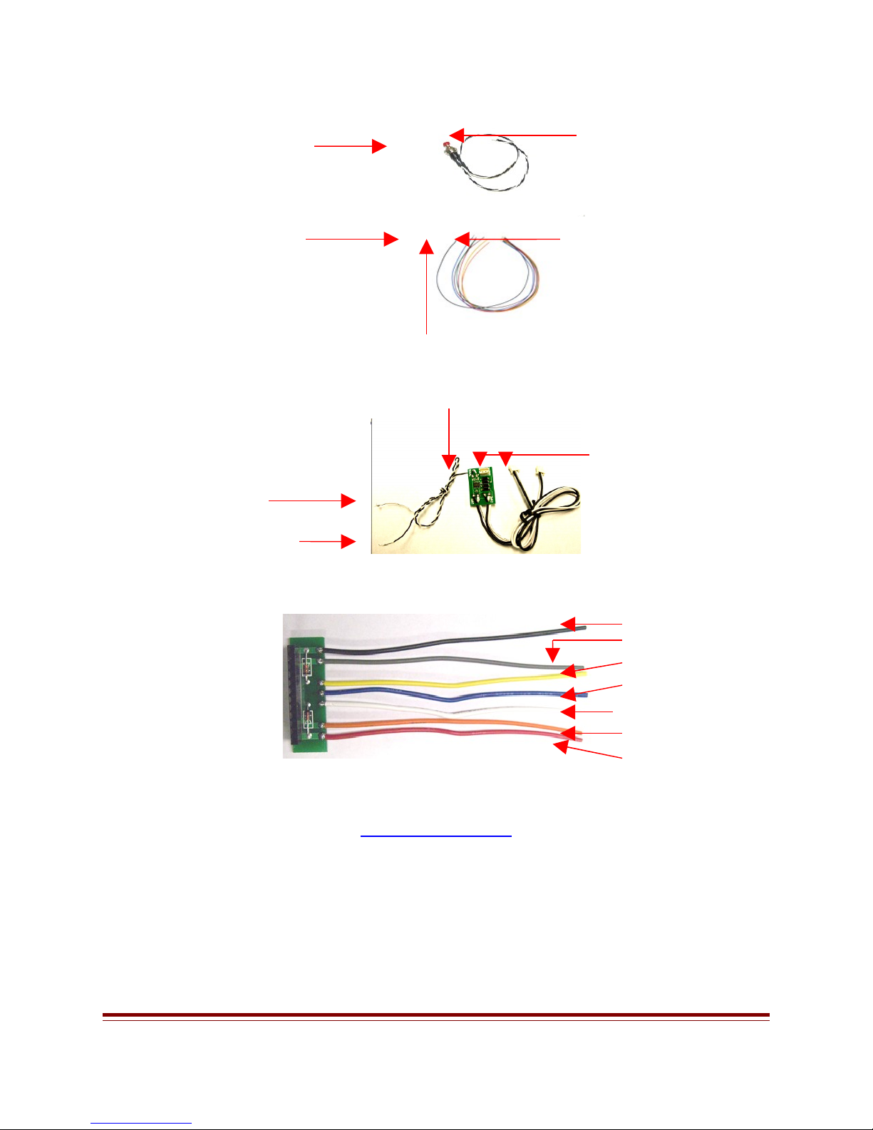
5. AUXILIARY WIRE HARNESS LABEL
Blue Wire Horn
Green Wire Bell
Yellow Wire Whistle
Orange Wire Brake
Red Wire Lights
Brown Wire Smoke
Black Wire Common
Auxiliary Wire Color Auxiliary Wire Harness Functions
6. SMOKE CONTROL BOARD
a. The smoke control board controls one or two smoke units.
b. To install the smoke control board remove the cables from the smoke units on the
locomotive.
c. Plug the cable that you remove into the small socket on the smoke control board.
d. Plug the two cables from the smoke control board into the smoke units.
e. Connect black wire on the smoke to the black common wire on the auxiliary wire‘ ’
harness.
f. Connect the white wire to any of the six aux functions.
g. Make sure the smoke switch on the locomotive is in the ON position.
h. The smoke unit must be in the LATCH position on the aux function.
7. WIRE HARNESS
a. Use the wire harness to hook up locomotive with out the new plug and play board.
RECEIVER ADAPTER WIRE COLOR WIRE USE
TRK +
MOT +
HD 1
HD COM
HD 2
MOT -
TRK -
BLACK RIGHT SIDE CAB POWER PICK-UP
GRAY RIGHT SIDE MOTOR TERMINAL
YELLOW REAR HEADLIGHT
BLUE HEADLIGHT COMMON
WHITE FRONT HEADLIGHT
ORANGE LEFT SIDE MOTOR TERMINAL
RED LEFT SIDE CAB POWER PICK-UP
2.4 TRAIN ENGINEER INSTRUCTION MANUAL NS Page 11 of 39
Page 12

8. RECEIVER INSTALLATION
STEP A. BEFORE ANY INSTALLATION; MAKE SURE THERE IS NO POWER ON
THE TRACK OR TO THE LOCOMOTIVE. The On Board receiver is designed to work
on track power or battery power of at least 12volts DC to a maximum of 24 volts DC. The unit
is self protected for polarity and input current. MAKE SURE THE YOU PLUG IN THE
RECEIVER CORRECTLY INTO THE MAIN PC BOARD ON THE ENGINE.
a. Remove the locomotive shell and jumper pin on the main PC.
b. Make sure the 12-10 pin connector on the receiver is facing the 12-10 pin socket on the
engine main PC board.
c. Plug in the On Board Receiver on the engine PC board.
d. Attach the Code set switch to the three-pin header on the receiver.
9. TRANSMITTER INSTALLATION
STEP B:
a. Remove the battery cover from the rear of the Transmitter
b. Insert three AA Alkaline, NiMH or Ni-cad batteries.“ ”
c. Replace the back cover on the transmitter.
10.CHARGING TRANSMITTER BATTERIES
a. Use three AA rechargeable batteries for the transmitter, N-CD or Nmh.‘ ’
b. At the bottom of the Transmitter there is an adapter jack to charge the batteries.
c. Batteries can be charge when the transmitter is turn, ON or OFF.
d. Plug the charger jack in the transmitter to charge the batteries.
e. When charging the battery the battery icon will move indicating it s charging. ’
f. When the batteries are fully charge, the battery icon will stop moving.
g. Charge the batteries overnight
A. Power ON/OFF pressed the ON/OFF key to turn on the Transmitter. Press and hold the‘ ’
ON/OFF key for 2 seconds to turn off the Transmitter
B. <<T / T>> -Used to select the active locomotive. Press the <<T key to scroll left and the T>>
to scroll to the right. The locomotive names and road numbers will be displayed on the main
operation screen. When the locomotive is set up under SU or MU it will also show up.
C. STOP/ENTER when operating a locomotive the STOP/ENTER button stops the active–
locomotive and sets its speed to zero. When accessing the menu STOP/ENTER is use to
conform a selection.
D. ARROW – When operating a locomotive the up and down arrows () increase or decrease
speed and the left and right arrows () select direction. When accessing menu items the up
and down arrows scroll between items and the left and right arrows change that item s value.’
E. MENU Select the unit s setup menus. When accessing menus pressing MENU will move you– ’
back one level like and escape or back key.
2.4 TRAIN ENGINEER INSTRUCTION MANUAL NS Page 12 of 39
Page 13

F. ALL STOP press and hold the 0 all stop key for 2 seconds and this will immediately stops all– “ ”
engines on the same group ID number and sets their speed to zero. To restart the active
locomotives press the <<T T>> to select the cab and press the UP arrow.–
G. NUMBER / LETTER KEYS Use when entering numeric or textual information the use of these–
keys is identical to those on a cell phone.
H. NUMBER KEYS 1-6 - When operating a locomotive, keys 1 through 6 are used to access six
auxiliary functions that may have been programmed into your engine s controller. For example,’
pressing key 1 might activate the sound card s whistle and 2 its bell sound while 3 might“ ” ’ “ ” “ ”
turn the smoke unit on or off. An extended mode will support 16 function keys.
I. NUMBER KEY # - When the Operating screen is being displayed pressing the # key accesses
the Quick Menu List.
J. NUMBER KEY 0 / ALL STOP - When the Operating screen is being displayed pressing the 0
key for 2 seconds will stop all locomotives and set their speed to zero. To restart locomotives
press the <<T or T>> keys to select a locomotive and press the up arrow
K. View MU Locomotive – When locomotives MU press the left bottom key [*⇑ ] on the
transmitter to view the locomotives that MU. To activate a locomotive functions e.g. bell,
horn, and smoke press the [*⇑ ] key to select the locomotive. When locomotive is selected, press
the number key to activate bell, horn, smoke etc.
11.CHARGER
STEP C:
a. To charge the batteries in the transmitter you need the correct charger.
b. Aristo Craft will have a charger available for the 2.4 Transmitter, CRE 57090.
c. Charger sold separately
12.TRACK POWER
STEP D:
a. By using power direct from your power supply to the layout at the highest setting it
will make the On Board receiver work better and the locomotive will run more
efficiently. The minimum voltage to use on the track is 12 Volt DC and the maximum
voltage is 24 Volt DC.
13.BATTERY POWER
STEP E:
The on board receiver will not handle more than 24 volts. ARISTO CRAFT have batteries
that will work with this receiver. On the Nmh and N_CD batteries, you need two to get the
correct voltage. Connect two Nmh batteries or two N_CD in series to get the right voltage.
To connect the batteries in series you need to have Y PLUG.
2.4 TRAIN ENGINEER INSTRUCTION MANUAL NS Page 13 of 39
Page 14

The numbers for the batteries and connectors as follows:
SPEED 0 .
a. CRE 55610 LI-ON, CRE 2amp 21.5 Volts
b. CRE 55611 Y Plug In Parallel
Y SU- L49 RdNo
CAB-0 DL 1.0s á 100%â 0
%
¡ DIR
14.SETUP AND LINK TRANSMITER AND RECEIVER TO RUN A SINGLE UNIT (SU)
STEP F:The transmitter s Operating screen displays a great deal of information about the’
locomotive that is being controlled
a. Place the locomotive on the track.
b. Make sure the pin on the On Board is plugged in correctly on the engine PC board.
c. Select track or Battery power on the switch panel on the locomotive.
d. Apply power to the track.
e. Press the ON/OFF on Transmitter and the LCD screen will show up.
Press the MENU button to go to the Main Set Up
Under main set up you can select any of the functions two ways (1 8)–
1. Press the Stop/Enter button or
2. Press the number for any of the functions below. (1 8) –
Press the MENU button once to select ASSIGN FUNCTIONS. Press the STOP/ENTER
button or [1] to select ASSIGN FUNCTIONS.
2.4 TRAIN ENGINEER INSTRUCTION MANUAL NS Page 14 of 39
Page 15

To enter a single locomotive (SU), under ASSIGN FUNCTIONS first you have to enter a
á
5 SYSTEM CONFIGURE
e. MOMENTUM [ 5% ]
á
LINK Address. Each locomotive must have its own LINK address.
The LINK ADDRESS comes with a default setting [49]. When [a] LINK address is selected,
press the left or right arrow to choose your LINK address.
IT IS IMPORTANT TO REMEMBER THE LINK ADDRESS FOR THE
LOCOMOTIVES THAT YOU ENTER IN THE TRANSMITTER.
If you forget the link address go to quick menu list on page 35 (A->Z name search)
Scroll down to
1. ASSIGN FUNCTIONS
i. HD LIGHT [ON]
j. TOP SPEED [100%]
k. START SPEED [ 0%]
l. AUX FUNC. SETUP
m. LINKING
enter the name,
road #,
momentum etc.
For more info
about assign
functions go to
1. ASSIGN FUNCTIONS
i. HD LIGHT [ON]
j. TOP SPEED [100%]
k. START SPEED [ 0%]
l. AUX FUNC. SETUP
m. LINKING PASSED
page 24.
STEP G. Press the code set switch on the locomotive for four seconds and the head light will
start to flash on the locomotive.
Scroll down to [M] LINKING and press the Stop/Enter button. After a few seconds the
locomotive headlight will stop flash and the transmitter will read LINKING PASSED.
If the LINKING failed check to make sure that the locomotive is receiving power from the
track or battery power. Follow the above steps [F-G] to re-link the transmitter and receiver.
Press the MENU button one time to go back one step and scroll down to USAGE OF CAB.
MAIN SET UP
1. ASSIGN FUNCTIONS
â
2. USAGE OF CAB
3. ADD MU/SU CAB
4. COPY LOCO
2.4 TRAIN ENGINEER INSTRUCTION MANUAL NS Page 15 of 39
STEP H.
Scroll down
and press the
1. ASSIGN FUNCTIONS
a. LINK ADDR [49]
â
b. RX TYPE [OnBoard]
c. NAME [GP -40]
d. ROAD NO. [ ]
Page 16

STOP/ENTER BUTTON or [2] to select USAGE OF CAB: The transmitter comes with a
SPEED 0 .
default setting of [5] CAB. To control more CAB press the right arrow.
Default Setting Add More Cabs
Press the MENU button one time to go back one step and scroll down to ADD MU/SU
CAB.
Ylll SU- GP-40 RD: 1802
CAB-0 DL 1.0s á 100%â
0 %
¡ DIR
STEP I. Press
2. USAGE OF CAB
CONTROL CAB
CAB 0 TO CAB - 5–
the
2. USAGE OF CAB
CONTROL CAB
CAB 0 TO CAB - 10–
STOP/ENTER button or [3] to select ADD MU/SU CAB:
When adding locomotive to your layout each locomotive MUST have its own CAB number
and LINK address.
Select the CAB Number that you want to run a Single Unit by pressing the right or left arrow.
Scroll down to (SU [49] L49.)
SU comes with a default LINK Address which is number [49].
To enter LINK address [00] quickly press the STOP/ENTER button.
Press the left or right arrow to select a Single Unit that you enter in the transmitter to add to
your Cab.
Press the MENU button twice to go to the main operating screen.
On the main screen it will show the single locomotive that you enter and cab number.
The link address number will not show up on the main operating screen.
2.4 TRAIN ENGINEER INSTRUCTION MANUAL NS Page 16 of 39
Page 17

REMEMBER EACH LOCOMOTIVE THAT YOU ENTER IN THE
SPEED 0 .
TRANSMITTER MUST ADD TO YOU CAB.
You are now linked and ready to run your train [Link Ok].
To add more single locomotives to the layout follow the above steps.
3. ADD MU/SU CAB
CAB NO: CAB 0–
MU MODE: OFF
Single Unit SU‘ ’
SU [49] L49
Cab Number
15.HOW TO RUN A SINGLE UNIT [SU] WITH THE TRANSMITTER
OPERATION:
STEP J:
The transmitter s Operating screen displays a great deal of information about the locomotive’
that is being controlled. Any of the functions below can change before or after you program
your Transmitter and Receiver.
a. Press the Left or Right Arrow for forward and reverse Direction.
b. To know which direction the locomotive is going, look on the LCD screen and the DIR
arrow will show the direction of the
locomotive (¡ DIR).
c. Test each locomotive to make sure that the
functions are working correctly. E.g. motor
Ylll SU- GP-40 RD: 1802
CAB-0 DL 1.0s á 100%â
0 %
direction and headlight direction. If you need to
change directions go to page 24 for more info
under Assign Functions.
¡ DIR
d. Use the up or down arrows () to
increase or decrease speed and the left and right arrows () to select direction
2.4 TRAIN ENGINEER INSTRUCTION MANUAL NS Page 17 of 39
Page 18

e. <<T / T>> -Used to select the active locomotive. Press the <<T key to scroll left and
5 SYSTEM CONFIGURE
e. MOMENTUM [ 5% ]
the T>> to scroll to the right. The locomotive names and road numbers, SU OR MU
will be displayed on the main operation screen.
f. Press the left bottom key on the transmitter to view MUed locomotive ‘ ’ [*⇑ ]
g. Press the menu button to enter the assign functions and change it settings MU or SU.
h. Press the # key to view and operate the aux functions and change the steps speed
settings.
MAIN SET UP
1. ASSIGN FUNCTIONS
â
2. USAGE OF CAB
3. ADD MU/SU CAB
4. COPY LOCO
1. ASSIGN FUNCTIONS
a. LINK ADDR [49]
â
b. RX TYPE [OnBoard]
c. NAME [GP -40]
d. ROAD NO. [ ]
16.SETUP AND LINK TRANSMITER AND RECEIVER TO RUN MULTIPLE UNIT (MU)
Main Set Up
STEP K. Press the MENU button once to select ASSIGN FUNCTIONS. Press the STOP/
ENTER button or [1] to select ASSIGN FUNCTIONS.
To enter multiple locomotives (MU), under ASSIGN FUNCTIONS first you have to enter a
LINK address for each locomotive. Each locomotive must have its own LINK address.
The LINK ADDRESS comes with a default setting [49]. When [a] link address is selected,
press the left or right arrow to choose your link address.
IT IS IMPORTANT TO REMEMBER THE LINK ADDRESS FOR THE
LOCOMOTIVES THAT YOU ENTER IN THE TRANSMITTER.
Scroll down to enter the name, road #, momentum etc. Test each locomotive and make sure
they are going in the same direction. For more info about assign functions go to page 24
2.4 TRAIN ENGINEER INSTRUCTION MANUAL NS Page 18 of 39
Page 19

STEP L. Press the code set switch for four seconds and the head light will start to flash on the
á
locomotive.
Scroll down to [M] Linking and press the Stop/Enter button. After a few seconds the
locomotive headlight will stop flashing and the transmitter will read LINKING PASSED.
If the linking failed check to make sure that the locomotive is receiving power from Track or‘ ’
battery
2. USAGE OF CAB
CONTROL CAB
CAB 0 TO CAB - 5–
power.
Follow step‘ f to’
re-link the
2. USAGE OF CAB
CONTROL CAB
CAB 0 TO CAB - 10–
transmitter and
receiver.
Press the MENU button one time to go back one step and scroll down to USAGE OF CAB.
STEP M. Scroll down and press the STOP/ENTER BUTTON or [2] to select USAGE OF
CAB:
The transmitter comes with a default setting of [5] cab. To control more cab press the right
arrow.
Default Setting Add More CABS
1. ASSIGN FUNCTIONS
i. HD LIGHT [ON]
j. TOP SPEED [100%]
k. START SPEED [ 0%]
l. AUX FUNC. SETUP
m. LINKING á
Press the
MENU button
one time to go
back one step
and scroll down
1. ASSIGN FUNCTIONS
i. HD LIGHT [ON]
j. TOP SPEED [100%]
k. START SPEED [ 0%]
l. AUX FUNC. SETUP
m. LINKING PASSED
to ADD
MU/SU CAB.
STEP N. ADD MU/SU CAB: you can only [MU] six (6) locomotives to a single CAB.
To run multiple locomotives you must choose a cab number. The cab number should be deferent
than the cab number in use.
E.g. if cab number (-0 -1-2) is in use, choose cab number (-3) to run the MU locomotives.
2.4 TRAIN ENGINEER INSTRUCTION MANUAL NS Page 19 of 39
Page 20

Any locomotive that you link in the transmitter have to be added to your track.
5 SYSTEM
SPEED 0 .
MU5 NOT SELECTED
Press the right or left arrow, to choose the cab number you want to run the MU locomotives.
Scroll down to [MU MODE: OFF] and press the right arrow to turn ON the MU mode
settings.
MU1 comes with a default link address which is number [49].
To enter the link address [00] quickly press the STOP/ENTER button
Press the right or left arrow to select the loco you want to run [MU].
Scroll down to (MU2-MU3-MU4-MU5 MU6) and select locomotives you want to run [MU].
If you enter a locomotive that you do not want to run MU, press the Stop/Enter button and it
will show NOT SELECTED . ‘ ’
STEP O:
Press the MENU button twice to back to the main screen.
On the main screen you will see the locomotives that you [MU]. Only one locomotive will
show up on the main screen that you MUed.
17.VIEW INDIVIDUAL MU LOCOMOTIVE
To view MU locomotives press the bottom
Ylll MU-GP-40 RD: 1802
CAB-0 DL 1.0s á 100%â 0
%
left key on the transmitter [*⇑ ].
You can view the MU locomotive and control the aux
functions.
When you selected a locomotive that you want to
¡ DIR
control and adjust its functions press the MENU button once.
Select 1. ASSIGN FUNCTIONS and press number [1] key on the transmitter to adjust the
functions as necessary, aux functions and step speed.
For more info about auxiliary functions go to page 26
MAIN SET UP
1. ASSIGN
FUNCTIONS â
2. USAGE OF CAB
3. ADD MU/SU CAB
4. COPY LOCO
ADD MU/SU CAB
CAB NO: CAB-0
â
MU MODE: OFF
SU [49] L49
ADD MU/SU CAB
CAB NO: CAB-0
â
MU MODE: ON
MU1 [49] L49
MU2 NOT SELECTED
View MU locomotives
2.4 TRAIN ENGINEER INSTRUCTION MANUAL NS Page 20 of 39
Page 21

18.LOCOMOTIVE RUNNING IN THE OPPOSITE DIRECTION
Stop all engines before changing any functions on MU locomotives.
1] Select the locomotive that is going in the opposite direction by pressing the [*⇑ ] key on the
transmitter. When the loco is selected press the MENU button and select ASSIGN
FUNCTIONS by pressing number [1] key on the transmitter.
Scroll down to the functions that need to be changed.
E.g. motor, head DIR, headlight ON/OFF Aux Func etc
19.OPERATE SMOKE AND SOUND ON INDIVIDUAL MU LOCOMOTIVE
Stop all engines before changing any functions on MU locomotives.
SMOKE UNIT CONTROL
1] Select the MU locomotive that you need to operate the smoke unit on by pressing the
[*⇑ ] on the transmitter keypad. When the locomotive is selected, press the MENU button
once. Select ASSIGN FUNCTIONS by pressing number [1] on the transmitter keypad.
Scroll down AUX FUNC. SETUP and press the Stop/Enter button. If you have the smoke
unit hooked up to auxiliary function [F3:] scroll down to [F3] and press the left arrow for LATCH.
Do not use the momentary for smoke because it will turn the smoke on and off very quickly.
Press the MENU button 3 times to back to the main screen.
To turn ON the smoke unit, press number [3] key on the transmitter.
To turn OFF the smoke unit, press number [3] again on the transmitter.
SOUND UNIT CONTROL
2] Select the MU locomotive that you need to operate the sound unit by pressing the [*⇑ ]on
the transmitter keypad. When the locomotive is selected, press the MENU button once. Select
ASSIGN FUNCTIONS by pressing number [1] on the transmitter keypad.
Scroll down to Aux Func Setup and press the Stop/Enter button. Press the right or left arrow
for momentary or latch.
MOMENTARY will turn the bell or horn on and off.
Latch will make the bell and horn work continuously.
Under momentary, when number [1] key on the transmitter is pressed for bell and the bell is
working continuously press [1] again to turn it off.
For more info go to page 26
2.4 TRAIN ENGINEER INSTRUCTION MANUAL NS Page 21 of 39
Page 22

When the number [1-6] on the transmitter key pad is pressed for aux function it will show up on
F1 ¡ DIR
SPEED 0 .
the main LCD screen as [F1-F6].
Aux Function
20.CHANGING THE SETTING BETWEEN ‘SINGLE UNIT [SU]’ TO ‘MULTI UNITS
[MU]’ TO ‘SINGLE UNIT [SU]’
SINGLE UNIT ‘SU’
1] First you have to link each locomotive individually. It is important to remember the link
address for each locomotive.
For example you have three locomotives SD45 GP40 Dash 9 . The first locomotive SD45 you‘ ‘
link it under link address (00) the second GP40 under link address (01) and the third Dash 9
under link address (02).
Now you have to separately select a cab number for each locomotive under Add MU/SU
CAB.
Choose a cab number to run the above locomotive.
E.g. the (CAB NO:-0 SD45 ) (CAB NO: -1 GP40 ) AND (CAB NO: -2 DASH 9 . When“ ” “ ” “ ”
finished go to (SU [00] L49) and select the locomotive the above locomotives. Each loco must
have its own cab number and link address.
Do not confuse yourself with LINK ADDRESSES AND CAB NUMBERS.
MULTI UNITS ‘MU’
You do not need to relink the above locomotives to run MU. If you decided to add more
locomotives to run MU, only then you need to link the locomotives with a new link address
number. Remember each locomotive must have its own link address number and cab #.
1] To MU the above locomotives go to USAGE OF CAB and select the number of CAB you
are running e.g. (10).
2] Go to ADD MU/SU CAB and select a cab number
to run the MU locomotives on e.g. [5].
Scroll down to MU MODE and press the right
Ylll MU-GP-40 RD: 1802
CAB-0 DL 1.0s á 100%â 0
%
arrow to turn ON the MU setting.
Scroll down to MU1 and select (MU1 [00] SD45)
Scroll down to MU2 and select (MU2 [01] GP40)
Scroll down to MU3 and select (MU3 [02] Dash 9)
2.4 TRAIN ENGINEER INSTRUCTION MANUAL NS Page 22 of 39
Page 23

When returning to the main screen and the fast button is pressed, all three locomotives will run
SPEED 0 .
MU3 [03] DASH 9
on Cab [5] at the same time.
Link Address No
SINGLE UNIT ‘SU’
If you decided to run the above locomotives individually you do not need to relink or change cab
numbers. Again it is important to remember the link address and cab number you have for the
ADD MU/SU CAB
CAB NO: CAB-0
â
above
Ylll SU-SD45 RD: 1802
CAB-0 DL1.0s á 100%â 0
%
MU MODE: OFF
SU [00] SD45
¡ DIR
locomotives.
To go back to the single unit operation press the left [<<T] or right [>>T] key.
a] Press the left [<<T] key until [CAB-0] show up on the main operating screen. The top line
on the main operating screen will show [SU-SD45].
b] Press the right [>>T] key for [CAB-1] and the GP40 will show up.
c] Press the right [>>T] key for [CAB-2] and the Dash9 will show up.
ADD MU/SU CAB
CAB NO: CAB-5
â
MU MODE: ON
MU1 [01] SD45
MU2 [02] GP40
If a locomotive does not show up under the correct cab
number, go to ADD MU/SU CAB and select the
correct cab number and link address number.
2.4 TRAIN ENGINEER INSTRUCTION MANUAL NS Page 23 of 39
Page 24

Link locomotive if you forg0t the Link address and cab number
5. SYSTEM CONFIGURE
MAIN SET UP
1. ASSIGN FUNCTIONS
â
2. USAGE OF CAB
3. ADD MU/SU CAB
4. COPY LOCO
To enter the MAIN SET UP press the MENU button
21.MAIN SET UP
1. ASSIGN FUNCTIONS
2. USAGE OF CAB
3. ADD MU/SU CAB
4. COPY LOCO
5. SYSTEM CONFIGURE
6. RADIO CONFIGURE
7. MY MEMO
8. RESET MEMORY
Any functions under main set up can be entered in two ways.
a] press the Stop/Enter button on the transmitter
b] Press the number [1-8] on the transmitter to enter its function.
22.1. ASSIGN FUNCTIONS:
To enter this function press the MENU button once
All functions listed below will enter in upper and lower case by using the left or right arrow.
a] LINK ADDRESS: [00-49] The link address comes with a default setting which is [49]. First the link
address for the locomotive must be chosen. To start from [00] quickly press the Stop/Enter
button. (Note: when linking a single unit [SU] multi unit [MU] each locomotive must have its
own linking address). Press the left or right arrow to select link address number.
2.4 TRAIN ENGINEER INSTRUCTION MANUAL NS Page 24 of 39
Page 25

b] RX TYPE: [On Board / Base Rx] this option is use for which RX you are using. This option
should be set to ONBOARD. The Base Receiver is use for your Cab side or accessory
controller.
c] NAME: use the keypad to type numbers or letters to name the engine. Names may be up to 9
characters long, e.g. [GP40] EGGLINER OR MIKADO. To DELETE any numeric or
textual information press the # key.
d] ROAD NO: [5533] enter a road number of up to four characters
e] MOMENTUM: [0 - 100%] this sets the locomotive s momentum, the rate at which it accelerates or’
decelerates. The higher the momentum value the slower the locomotive will speed up when you
press the up arrow for acceleration.
f] DELAY : [0 5 sec] When the direction of the locomotive is reversed this setting determines how–
long, in seconds, that the locomotive will be completely stopped before it starts up again in the
other direction. The range is 0 to 5 seconds in 1/10th second increments.
g] MOTOR: [Rev Nor] sets the default direction of travel when the transmitter says the–
locomotive is going forward. This can be set to NOR (normal) or REV (reverse). If set to
normal NOR the locomotive will go forward. When direction [¡ DIR ] on the transmitter
shows that it is going forward. If set to reverse [REV] it will go backwards. Not all the
locomotive will run forward when the transmitter is set to normal [NOR].
h] HD DIR: [Rev Nor] sets the direction that the locomotive will be traveling for the headlight to–
be lit. This can be set to NOR (normal) or REV (reverse). If set to normal [NOR] the
headlight on the locomotive will come on when the locomotive is going forward. If set to
reverse [REV] the headlight will come on when the locomotive is going backwards Not all the
locomotive will run forward when the transmitter is set to normal [NOR].
i] HD LIGHT: [OFF/ON] turn the locomotive headlight ON or OFF. When this function is set to
on or off the headlight will not turn on or off until you return to the main operating screen.
j] TOP SPEED: [50 100%] sets the locomotives top speed as a percentage of its possible top speed.–
Increase or decrease the speed on the locomotive. This comes in handy if you have visitors who
are operating your trains and have been known to run them at too high a speed. If you set this
to 70% that is all the faster the locomotive will go, 70% of its possible top speed.
k] START SPEED: [0 25%] sets the speed at which acceleration of the locomotive begins. Start–
speed on 0% will start the loco slowly, 25% will start the loco quickly. If you have a large
locomotive or one that is pulling a long, heavy train you can set the start speed so that the
power level will jump to the set percentage as soon as you begin accelerating. For example, if
you have a locomotive that doesn't start moving till the throttle setting is at 25% you can set
2.4 TRAIN ENGINEER INSTRUCTION MANUAL NS Page 25 of 39
Page 26

the start speed to that number and not have to wait for the speed to get to that level before the
train moves. As soon as you press the UP ARROW the speed will jump to 25%.
AUX FUNC SETUP
AUX MODE: BASIC
â
F1: MOMENTARY
F2: MOMENTARY
F3: LATCH
F4: MOMENTARY
l] AUX FUNCTION SETUP : Press the STOP/ENTER
button and AUX FUN SETUP will show.
To change the functions below from momentary to latch
i. AUX MODE: EXTEND/BASIC .
ii. To choose basic or extended press the left or right arrow.
iii. To change from momentary to latch press the right or left arrow.
iv. BASIC: this will only control 6 auxiliary functions, [F1 to F6].
v. EXTENDED: this will control all 16 auxiliary functions, [F1 to F16].
vi. LATCH: this will make any aux function work continuously. If you have the bell sound
hook up to F1 on the AUX output, and [1] key is pressed on the transmitter, this will
turn the Latch Function ON. To turn OFF Latch Function, press the [1] key on the
transmitter keypad.
vii. MOMENTARY : Press the number [2] key on the transmitter and the horn sound will turn on
and turn off by itself. Press and hold number [2] key on the transmitter and the how will
sound until the key is released.
viii. The six auxiliary buttons (#1 through #6 on the keypad) can be configured to operate
your other sound boards.
ix. See your sound board s documentation of consult on-line resources for installation of’
sound boards.
2.4 TRAIN ENGINEER INSTRUCTION MANUAL NS Page 26 of 39
Page 27

m] Linking: Associates a particular locomotive s description and settings with a particular’
m. LINKING PASSED
m. LINKING
receiver. Each locomotive must be bound before it can be operated.
To link a locomotive:
1. If running on batteries make sure the locomotive s battery is fully charged. If using Cab’
power turn on power to the Cab that the locomotive is on.
2. Press and hold the LINK button for four second on the locomotive. Release the Link
button when the red LED on the receiver board and the locomotive s lights begin’
flashing.
3. While the lights are flashing select menu item m. LINKING and press the
STOP/ENTER button.
4. In a moment the screen will show that the programming of the unit has been successful
1. ASSIGN
LOCOMOTIVE
i. HD LIGHT [ON]
j. TOP SPEED [100%]
k. START SPEED [ 0%]
l. AUX FUNC. SETUP
1. ASSIGN
LOCOMOTIVE
i. HD LIGHT [ON]
5. On the
j. TOP SPEED [100%]
k. START SPEED [ 0%]
l. AUX FUNC. SETUP
and the
flashing
will stop.
transmitter it will read linking passed. The main screen will show LINK OK.
2.4 TRAIN ENGINEER INSTRUCTION MANUAL NS Page 27 of 39
Page 28

23.Under Quick Menu List
You can check to see if the smoke on the latch or momentary function is in the ON/OFF
position. Press the # key select AUX FUNCTIONS and press the STOP/ENTER button.
You can turn these functions ON or OFF by pressing the STOP/ENTER BUTTON.
Auxiliary Function Table
AUX OUT
ON RX
F1 1 LATCH/MOMENTARY F1 F1
F2 2 LATCH/MOMENTARY F2 F2
F3 3 LATCH/MOMENTARY F3 F3
F4 4 LATCH/MOMENTARY F4 F4
F5 5 LATCH/MOMENTARY F5 F5
F6 6 LATCH/MOMENTARY F6 F6
F7 7 LATCH/MOMENTARY F7
F8 8 LATCH/MOMENTARY F8
F9 9 LATCH/MOMENTARY F9
F10 10 LATCH/MOMENTARY F10
F11 11 LATCH/MOMENTARY F11
F12 12 LATCH/MOMENTARY F12
F13 13 LATCH/MOMENTARY F13
F14 14 LATCH/MOMENTARY F14
F15 15 LATCH/MOMENTARY F15
F16 16 LATCH/MOMENTARY F16
PRESS KEY ON TX TO
ACTIVATE SOUND ETC
FUNCTIONS BASIC FUNCTION EXTENDED
FUNCTION
2.4 TRAIN ENGINEER INSTRUCTION MANUAL NS Page 28 of 39
Page 29

24.Sound installation on auxiliary wires Harness Table
Dallee Sound Card / Wire Plugs From Main PC Loco 7 Pin Auxiliary Wire Harness
J3 –Black
J3 –White
J1 –Red –Not connected
J1 –Gray
J2 –Red –Not connected
J2 –Gray
J4 –Red
J4 –Gray
Connect to Red Power wire 2 Pin
Connect to Green Power wire 2 Pin
Connect to Red Power wire 2 Pin
Black Common –
Blue Horn –
Green Bell –
The outputs from the Auxiliary Plug can be wired in parallel with reed switches so that your
sound card can ring its bell or sound its whistle from buttons on the transmitter and from
magnets on the Cab that the trigger reed switches. This diagram shows how they need to be
wired.
a] LINK OK, NO LINK: Normally the transmitter s main control display shows LINKOK on the’
bottom line of the screen. This indicates that there is a good radio link between the transmitter
and the receiver in the locomotive. If that link is lost due to an exhausted battery, excessive
2.4 TRAIN ENGINEER INSTRUCTION MANUAL NS Page 29 of 39
Page 30

distance, a short on the Cab, a derailment or no power on the Cab the message will change to
NOLINK. When the amperage drawn by a locomotive exceeds the capacity of the onboard
receiver, which can supply 5amps continuous, the receiver will shut down and the transmitter
will display OVERLOAD on the LCD. After you correct that condition pressing the zero
key [0] on the transmitter keypad will reset the error message.
b] OVERLOAD: When the amperage draw exceeds the capacity of the onboard receiver, which is
5amp continuous the receiver shut down and the transmitter will indicate an OVERLOAD on
the LCD. After you correct that condition pressing the [0] on the transmitter keypad that will
bring us to the former status.
Note if the STOP/ENTER button is pressed; you have to restart your locomotive.
c] OVERHEAT: The receiver will send an OVERHEAT signal to the Transmitter if the
temperature reaches 180 degrees Fahrenheit. If the receiver overheat wait for 5 to minutes for the
receiver to reach it s temperature and press the [’ 0] key on the transmitter and that will bring us to the
former status.
25.2. USAGE OF CAB:
Usage of Cab comes with a default setting of [5] Cab [CAB -0 TO CAB-5].
You can add or remove Cab number by pressing the right of left arrow.
If you have ten locomotives and you are only running eight, just add eight Cabs to the
transmitter.
Press the menu button twice to go back to the main operating screen.
26.3. ADD MU/SU CAB
Add MU/SU Cab is used to select a single unit or
multiple units to add or remove from the layout.
SU ‘SINGLE UNIT’: Each locomotive must have its own link address and Cab number.
Go to ASSIGN FUNCTIONS and select a link address.
Scroll down to [m] linking and press the Stop/Enter button to link the locomotive.
Select a Cab number that you want the locomotive to run on, under ADD MU/SU CAB.
2.4 TRAIN ENGINEER INSTRUCTION MANUAL NS Page 30 of 39
2. USAGE OF CAB
CONCABOL CABS
CAB-0 TO CAB-8
Page 31

Scroll down to [SU [00] L49] and select the locomotive you want to run. The locomotive will
SU [00] L49
run under the Cab number you selected.
Press the MENU twice button to return to the main screen.
To add more single locomotives, follow the above steps
MU ‘MULTI PLE UNITS’: before any locomotives are MUed, you must link each locomotive
with a different link address. Only six MU locomotives can run on a single Cab number.
Select a Cab number that you will run the MU locomotives on. Scroll down to (MU MODE)
and press the right arrow to turn the MU setting ON.
3. ADD MU/SU
CAB
CAB NO: CAB-0
MMODE: OFF
Scroll down to [MU1 through MU6] to add locomotives
Press the right or left arrow to enter a locomotive.
E.g. if you have three locomotives, (1st loco on Cab [-0] Link
Address [00] SD45) (2nd loco on Cab [-1]) [Link Address [01] GP40)
(3rd loco on Cab [-2] Link Address [02] Dash-9)
Choose a different Cab number to run the MUed locomotives, e.g. Cab [-3]
If you enter a locomotive incorrectly press the Stop/Enter button to remove the locomotive
NOT SELECTED .‘ ’
27.4. COPY LOCO :
Once you set up a locomotive with a set of options you can copy that locomotive's
characteristics to another locomotive based on its link address. For example, if you have set up
link address 00 and want to copy it to link address 01 just select 00 as the FROM: and 01 as
the TO: and move to COPY and press STOP/ENTER.
This function will only copy the data from one
locomotive to the other.
BEFORE COPY
AFTER COPY
2.4 TRAIN ENGINEER INSTRUCTION MANUAL NS Page 31 of 39
3. ADD MU/SU CAB
CAB NO: CAB -1
MU MODE: ON
MU1 [00] SD45
MU2 [01] GP40
MU3 [02] DASH 9
Page 32

4. COPY LOCO
FROM: [00] SD45
TO: [01] SD45
COPY: [00] -> [01]
When
4. COPY LOCO
FROM: [00] SD45
TO: [01] PACIFIC
COPY: [00] -> [01]
finished selecting the loco, press the STOP/ENTER button to copy.
To exit press the MENU button twice.
2.4 TRAIN ENGINEER INSTRUCTION MANUAL NS Page 32 of 39
Page 33

28.5. SYSTEM CONFIGURE:
d. KEY SOUND
To enter this function press, the STOP/ENTER button.
a. POWER ON/OFF : [1 60 MIN] use this function to set the minutes to turn off the–
transmitter power by pressing the right or left arrow. When you are not using the
transmitter it will turn off by it self.
b. BRIGHTNESS : [0 100%]: use this function to adjust the brightness on the LCD screen by–
pressing the left or right arrow. It will affect battery life obviously.
c. CONTRAST : [0 100 %] use this function to adjust the text color or number color on the–
LCD screen by pressing the left or right arrow.
d. KEY TONE : [ON OFF] uses this function to turn the sound tone on the transmitter ON–
or OFF.
e. To exit press the MENU button twice.
5. SYSTEM CONFIGURE
a. POWER OFF [10 min]
b. BRIGHTNESS
[50%]
c. CONTRAST [L
10]
29.6. RADIO CONFIGURE
To enter this function press, the STOP/ENTER button.
a) RF –CHANNEL :
[CH: 11 26] you can change the channel numbers if you are experiencing interference. To–
change the channel numbers, press the right or left arrow.
b) GROUP ID:
2.4 TRAIN ENGINEER INSTRUCTION MANUAL NS Page 33 of 39
Page 34

This feature will allow several people to have control over their locos even if they use the same
Cab #’s for controlling their loco. The group I.D. is transmitted to the loco from each transmitter
with a different setting and the receiver will not acknowledge messages from transmitters with a
different group code. The group code is set randomly for each transmitter and will self generate
the same number for each cab assigned.
8. RESET MEMORY
ARE YOU SURE
RESET ALL MEMORY?
YES - NO
6. RADIO CONFIGURE
a. RF-CHANNEL
30.7. MY MEMO:
Name:
[GH: 16]
b. GROUP ID
[0005]
Info:
To exit press the MENU button twice.
8. RESET MEMORY
WAIT••••
31.8. RESET MEMORY
1. To reset the transmitter to the factory settings
press the left arrow to select the YES and press
and hold the Stop/Enter button for four seconds
and
2.4 TRAIN ENGINEER INSTRUCTION MANUAL NS Page 34 of 39
7. MY MEMO
NAME:
_______________________
INFO:
_______________________
When Yes is chosen
Page 35

AUX FN MODE OUTPUT
2. To exit press the MENU button twice.
F1: LAT ON
F2: LAT ON
F3: MMT OFF
F4: MMT OFF
F5: MMT OFF
32.QUICK MENU LIST
a] AUX FUNCTION: This menu item is under the Quick Menu List It shows each function–
and whether it is set to Latch or Momentary. It also shows the current setting for each
function. This is an easy way to see, for example, if your smoke unit is on or off. You can also
change the setting of each function by highlighting it and pressing STOP/ENTER.
b] AUX FN MODE OUT PUT :
Under the aux function mode output you can only
change the Latch to ON or OFF by pressing the STOP/
ENTER.
When you set the aux function setup to basic it will only show up six aux function, Extended
will show all sixteen functions.
2.4 TRAIN ENGINEER INSTRUCTION MANUAL NS Page 35 of 39
QUICK MENU LIST
AUX FUNCTIONS
STEP SPEED
[t2]
A->Z NAME SEARCH
ABOUT SYSTEM
Page 36

c] STEP SPEED: [1 5] –
Loco Name Rd No [04]
This menu item is under the Quick Menu List - The step speed can range from 1-5.
When set to 1 the rate at which the speed increases when you hold the UP ARROW will be
at its slowest. A higher number will cause this rate to increase. When set to its highest value
the speed can change from 0 to 100% very rapidly. For precise control of a locomotive s speed’
set it to 1 or 2. To have your locomotives accelerate very rapidly set it to 4 or 5.
When Step Speed is set to 1 it changes in increments 0.1 %.
When step speed is set to 2 it changes in increments of
0.5 %.
When step speed is set to 3 it changes in increments of
1.0%.
When step speed is set to 4 it changes in increments of
2.5%.
A->Z NAME
SEARCH
Loco Name Rd No [00]
Loco Name Rd No [01]
Loco Name Rd No [02]
Loco Name Rd No [03]
When step speed is set to 5 it changes in increments of
5.0%.
Step Speed
Setting
Number Of Speed Steps Increment on Each
Key Press
Use
1 1000 1/10 Very delicate operation
2 200 ½
3 100 1 Normal Operation
4 40 2 ½
5 20 5 Rapid speed up & slow
down
d] A – >Z NAME SEARCH: To enter this function, press the STOP/ENTER key, A ->Z
NAME SEARCH. Name search will only show you the names, road numbers and address
numbers of the locomotive that is enter in the transmitter.
2.4 TRAIN ENGINEER INSTRUCTION MANUAL NS Page 36 of 39
Page 37

e] ABOUT SYSTEM: press and hold the STOP/ENTER button it will show the system info:
To exit pressed the MENU button once.
ABOUT SYSTEM
33.WIRE HARNESS ADAPTER INSTALLATION
FRQ: 2.4GHz/US
VER 1.14
a. POWERING THE ON BOARD RECEIVER :
The wire harness adapter is use for locomotives
with out the plug and play board. The On
Board receiver is designed to work on track
power or batter power of at least 12volts DC
to a maximum of 24 volts DC. The unit is self protected for polarity and input current.
b. CONNECT THE POWER WIRES :
Solder the black (TR+) wire and red (TR-) wire from the Wire Harness Adapter to the
power pickup in the locomotive. All power wires must be isolated from all other wiring
before installation.
WIRE HARNESS WIRE COLOR WIRE USE
TRK + BLACK RIGHT SIDE CAB POWER PICK-UP
TRK - RED LEFT SIDE CAB POWER PICK-UP
c. ISOLATE THE MOTOR (S):
2.4 TRAIN ENGINEER INSTRUCTION MANUAL NS Page 37 of 39
Page 38

The motor (s) must be isolated from ALL other wiring before the on board receiver can
be installed in a locomotive. After you have disconnected the motor wires form the
locomotive you can now solder the wires from the wire harness adapter to the motor as
shown below.
WIRE
HARNESS
MOT + GRAY RIGHT SIDE MOTOR TERMINAL
MOT - ORANGE LEFT SIDE MOTOR TERMINAL
WIRE COLOR WIRE USE
d. CONNECTING THE HEADLIGHTS :
All of the wiring to the headlights MUST be isolated from all other wiring.
WIRE
HARNESS
HD 1 YELLOW REAR HEADLIGHT
HD COM BLUE HEADLIGHT COMMON
HD 2 WHITE FRONT HEADLIGHT
WIRE COLOR WIRE USE
e. SECURING THE ON BOARD : The On Board should be insulated and secure from any
metal inside the engine. The On Board can be attached to the shell or interior floor of
the engine with double stick foam tape.
f. PLUG IN THE ON BOARD RECEIVER TO THE WIRE HARNESS SOCKET .
Make sure that there is no power on the track or locomotive when you are going to
install the On Board Receiver to the wire harness socket.
Check to make sure the 12 pin on the On Board Receiver is plugged in correctly to the
wire harness socket.
The wire harness adapter has a 12 position socket. Plug in the wire harness socket to the
On Board 12 pin connector correctly.
2.4 TRAIN ENGINEER INSTRUCTION MANUAL NS Page 38 of 39
Page 39

2.4 TRAIN ENGINEER INSTRUCTION MANUAL NS Page 39 of 39
Page 40

Regulatory Statements to be included in the Users Guide for Sputnik
USA-Federal Communications Commission (FCC)
This device complies with part 15 of the FCC Rules. Operation is subject to the following
two conditions: (1) This device may not cause harmful interference, and (2) this device
must accept any interference received, including interference that may cause undesired
operation.
This equipment has been tested and f o un d t o compl y wit h the limits for a Class B digital
device, pursuant to Part 15 of FCC Rule s. These limits are designed to pro v i de reasonable
protection against harmful interference in a residential installation. This equipment
generates, uses, and can radiate radio frequency energy. If not installed and used in
accordance with the instructions, it may cause harmful interference to radio
communications. However, there is no guarantee that interference will not occur in a
particular installation.
If this equipment does cause harmful interference to radio or television reception, which
can be determined by tuning the equipment off and on, the user is encoura ge d to t ry and
correct the interference by one or more of the following measures:
-Reorient or relocate the receiving antenna
-Increase the distance between the equipment and the receiver.
-Connect the equipment to outlet on a circuit different from that to which the receiver is
connected.
-Consult the dealer or an experienced radio/TV technician for help.
Any changes or modifications not expressly approved by the party responsible for
compliance could void the user’s authority to operate the equipment.
Caution: Exposure to Radio Frequency Radiation.
To comply with FCC RF exposure compliance requirements, for mobile configurations, a
separation distance of at least 20 cm must be maintained between the antenna of this device and
all persons.
This device must not be co-located or operating in conjunction with any other antenna or
transmitter.
 Loading...