

Page 1

VERSION 3.0
Software
Manual
VERSION 3.0
Page 2

Crest Audio Inc.
100 Eisenhower Drive
Paramus NJ 07652 USA
TEL 201.909.8700 FAX 201.909.8744
http://www.crestaudio.com
NexSys Software v. 3.0 Manual
v 1.0 13 August 1997
© 1997
*C4400008*
Page 3

Crest Audio Inc. NexSys v. 3.0
Table Of Contents
Page
1. INTRODUCTION 1.1
1.1 What is included in this manual 1.1
1.2 What is not included 1.2
1.3 System Requirements 1.2
1.4 Manual Conventions 1.2
1.5 Software Conventions 1.2
Use of the Mouse Buttons 1.3
1.6 Software Installation 1.3
1.7 Technical Support 1.3
2. OVERVIEW 2.1
Devices 2.1
Plans 2.1
Groups 2.2
Snapshots - Plan & Group 2.2
Scenes 2.2
Event Monitor 2.2
Software Security 2.2
Event Scheduler 2.2
Load Monitoring 2.3
Audio Return 2.3
MIDI Interfaces 2.3
3. NETWORK TOPOLOGY 3.1
3.1 Amplifier Classes 3.1
3.2 Networks, Nodes and Buses 3.1
Hubs 3.3
Supervisors (Pro class) 3.3
Load Monitor Mainframe (Pro class) 3.4
3.3 Network Terminations & Wire Type 3.5
3.4 Network Addressing 3.5
4. BUS SERVER INSTALLATION AND CONNECTION 4.1
4.1 Installing the Bus Server Card 4.1
Connecting the Bus Server to the NexSys Bus 4.1
4.2 Communicating with the Bus Server 4.2
Changing the Bus Server’s I/O Address 4.2
5. THE TOOLBAR & MENUS 5.1
5.1 Toolbar 5.1
5.2 Menus 5.2
5.3 Right Mouse Menus 5.2
TOC 1
Page 4

NexSys v. 3.0 Crest Audio Inc.
6. BUILDING APLAN 6.1
6.1 Making a New Plan 6.1
6.2 AutoPlan 6.1
6.3 Manually Adding devices 6.2
6.4 Saving Your Plan 6.3
6.5 Plan Inventory 6.3
6.6 Device Setup 6.4
Changing the Device’s Name 6.4
Changing the Device’s Address 6.5
6.7 Venue Bitmap Background 6.6
7. GROUPS 7.1
7.1 Creating a group 7.1
7.2 Renaming a group 7.1
7.3 Deleting a group 7.1
7.4 Adding devices to the group 7.1
Moving a device 7.2
Copying a device 7.2
Selecting Multiple devices 7.2
7.5 Quickly Opening a group 7.3
7.6 Group Views 7.3
Group List View & the Plan Inventory 7.3
Group Console Views 7.4
8. NEXSYS FAULTS, ALERTS & EVENTS 8.1
8.1 Alert Panels 8.1
8.2 Amplifier Warning Thresholds 8.2
8.3 Event Monitor and the Event Log 8.2
Opening the Event Monitor 8.2
Event Log Setup 8.2
9. CONTROLLING YOUR AMPLIFIERS 9.1
9.1 Amplifier Controls 9.1
Amplifier Level Control 9.1
Amplifier Mute Control 9.1
Amplifier Solo Control 9.2
Amplifier Polarity 9.2
Audio Return 9.2
VU Meters 9.2
9.2 Related devices 9.3
9.3 Group & Plan Amplifier Control Panel 9.3
Group/Plan Level 9.3
Group/Plan Mute 9.3
9.4 Control Hierarchy 9.4
9.5 Solo Safety 9.5
TOC 2
Page 5

Crest Audio Inc. NexSys v. 3.0
10. SNAPSHOTS 10.1
10.1 Inserting a New Snapshot 10.1
10.2 Recalling a Snapshot 10.1
10.3 Updating a Snapshot 10.2
10.4 Editing a Snapshot 10.2
10.5 Executing a Snapshot on Startup 10.3
10.6 Recalling Snapshots from Outside of NexSys 10.3
11. SCENES 11.1
11.1 Scene Maintenance 11.1
11.2 Recalling a Scene 11.1
12. SECURITY 12.1
12.1 Access Levels 12.1
12.2 Security Setup 12.1
12.3 Login / Logout 12.2
13. EVENT SCHEDULER 13.1
13.1 Event Setup and Operations 13.1
13.2 Report Modes 13.2
13.3 Example Application 13.2
13.4 MIDI HEX Programming 13.3
14. MIDI INTERFACE 14.1
14.1 Creating a MIDI Device within NexSys 14.1
14.2 Recalling MIDI Patches 14.1
15. LOAD MONITORING 15.1
15.1 Load Monitor Setup for CK family Amplifiers 15.1
15.2 Load Monitor Setup for Pro Class Amplifiers 15.1
15.3 The Reference Curve 15.1
16. CK FAMILY SEQUENTIAL TURN-ON/TURN-OFF (STO) 16.1
17. CK FAMILY INPUT MODULES & CONTROLPANELS 17.1
Appendix A- DECIMAL TO HEXADECIMAL CONVERSION TABLE
Appendix B - MENU REFERENCE
Appendix C - BUS SERVER DIP SWITCH SETTINGS
TOC 3
Page 6

NexSys v. 3.0 Crest Audio Inc.
Screen Captures and Drawings
Item Page
Plan Inventory Window 2.1, 6.3
NexSys Network with CK family amplifiers and hubs 3.2
Pro class network setup diagram 3.4
Amplifier Channel Setup Windows 3.5
Bus Server Card rotary switch locations 4.1
Bus Server Dialog Window 4.2
Toolbar 5.1
NexSys Menu Hierarchy 5.2, 5.3
Plan Name Window 6.1
NexSys Autoplan Window 6.2
Plan Inventory Toolbar Buttons 6.2
Device Setup Menu 6.4
CK family Amplifier Setup Window 6.5
Pro Class Amplifier Setup Window 6.5
MIDI Device Setup Window 6.6
Venue Bitmap Background Example 6.6
New Group Dialog Box 7.1
Group Selection Tool 7.3
Group List View 7.3
Group Console Views 7.4
Balloon Help example 7.5
Alert Panels and icons 8.1
Amplifier Warning Control Window 8.2
Single amplifier control panels 9.1
Amplifier Mute Control Button 9.1
Amplifier Solo Control Button 9.2
Amplifier Polarity Control Button 9.2
Audio Return Control Button 9.2
VU Meters 9.2
Related Devices Menu 9.3
Group and Plan Amplifier Control Panel 9.3
Group and Plan Level Control Panel 9.3
Control Hierarchy Examples 9.4
Control Hierarchy Diagram 9.5
Solo Safety Toggle 9.5
Insert Snapshot Dialog Box 10.1
Snapshot Window 10.2
Edit Snapshot Window 10.2, 10.3
Scene Maintenance Window 11.1
Security Administrator Dialog Window 12.2
NexSys Login Window 12.2
Define Event Window 13.1
MIDI Device Setup Window 14.1
MIDI Patch Control Window 14.1
Load Monitor Window 15.3
Plan Inventory (Sequential Tur n-On) window 16.1
CK family Input Module Control Panels 17.1
Bus Server End View Appendix C
TOC 4
Page 7

Crest Audio Inc. NexSys v. 3.0
1. Introduction
Thank you for purchasing NexSys - the powerful computer controlled audio system for your
Crest Audio power amplifiers. With its practical and intuitive graphical interface, NexSys
has won praise from audio engineers in every discipline. After familiarizing yourself with
NexSys, you will realize the value and flexibility that this software package offers.
1.1 What is included in this manual
The NexSys Software Manual is organized into several sections that will provide users with
the information necessary to set up and run a NexSys system.
Chapter 2 Overview. Presents an introduction to NexSys concepts and a guide
to each software section.
Chapters 3 & 4 Network Topology and Bus Server Installation & Connection.
Presents essential data on your NexSys system components and
their interface to the computer and the NexSys RS485 bus.
Chapter 5 Toolbar & Menus. Offers quick access to more frequently used
NexSys functions.
Chapter 6 Building a Plan. Details how to build a plan from user-defined
devices, groups, Snapshots, Scenes, and settings.
Chapter 7 Groups. Details how to facilitate the control of amplifiers and other
devices with NexSys groups.
Chapter 8 NexSys Faults, Alerts & Events. Covers the various faults, or alerts,
that are reported on screen and to the Event Monitor/Log.
Chapter 9 Controlling Your Amplifiers. Details the many ways in which ampli-
fiers may be controlled using NexSys.
Chapter 10 Snapshots. Records Plan & Group Snapshots.
Chapter 11 Scenes. How to create these graphical “desk top” arrangements,
which are collections of NexSys windows that can be opened for
viewing or control.
Chapter 12 Security. Details how to determine which controls are included in
scenes and limit access to those scenes via password protection
Chapter 13 Event Scheduler. Profiles one of the most powerful and useful tools
in the NexSys system. Event Scheduler allows the system operator
to automate all functions that can be executed by a user.
Chapter 14 MIDI Interface. Details how NexSys and the Event Scheduler can
interact with MIDI equipment via the NexSys MIDI Interface.
Chapter 15 Load Monitoring. Profiles this powerful diagnostic tool that pro-
vides a consistent means to verify performance of the drive lines
and speakers in the system.
Chapter 16 CK family Sequential Turn-On/Turn-Off (STO). Details how to
sequentially turn on and turn off these amplifiers with a delay
between each one.
Software Manual Page 1.1
Page 8

NexSys v. 3.0 Crest Audio Inc.
Chapter 17 CK family Input Modules & Control Panels. Covers signal process-
ing controls for NC modules.
Appendix A Menu Reference. A complete NexSys menu reference list.
Appendix B Decimal to Hexadecimal Conversion Table.
Appendix C Bus Server Dip Switch Setting Reference Table.
1.2 What is not included in this manual
A detailed explanation of the system hardware and wiring requirements is not included in
this manual, but can be found in the accompanying NexSys System Hardware Manual. A
brief resume of hardware addressing and configuration is included in this document in
Section 3, Network Topology. Additionally, specific information regarding amplifiers,
processor modules, and related peripheral devices can all be found in the various technical
data sheets or accompanying operator's manuals.
1.3 System Requirements
We recommend the following minimum computer configuration for NexSys 3.0 systems
• Intel Pentium or compatible computer
• Microsoft Windows 95
• 16 megabytes of RAM
• 10 megabytes of available hard disk space
• Video monitor and driver card capable of displaying a resolution of 1024x768
• Mouse
• High density 3 1/2" (1.44 MB) floppy drive
• Suggested Option- Add a modem with a third party remote control software
program such as PCAnywhere™ or Carbon Copy™ if you want to control the
system from a remote location.
1.4 Manual Conventions
Menu choices appear in the following manner throughout this manual: Plan | Save As...
Holding the ALT key down and pressing the underlined key will invoke that menu choice.
For example, ALT + P will drop down the Plan menu. This example also shows that there
is a sub-menu or sub-selection for the Plan menu. In this case it is the Save As menu.
Whenever this “information” icon is used,
you will find useful operating hints in italics.
1.5 Software Conventions
NexSys software version 3.0 runs under Microsoft W indows 95
™
. This manual is written for
those who have a working knowledge of Microsoft Windows. For further operating system
information, please refer to your Microsoft Windows documentation. (Please note that all
graphics used in this manual show NexSys operating under Windows 95.)
When running the NexSys program for the first time, the main window will appear with several pull down menus, a tool bar with controls and display icons. Clicking on a pull down
menu item with the left mouse button will bring out the sub-menu items under that partic-
Page 1.2 Software Manual
Page 9
Crest Audio Inc. NexSys v. 3.0
ular function. Valid menu selections are displayed in black while those that are not are
grayed out.
When the cursor is placed over an icon on the tool bar, a description of its function is displayed in the border at the very bottom of the NexSys window.
The term active window is used throughout this User’s Guide. An active window is the window in which you are currently working. It is the one with the highlighted title bar. Some
menu items and toolbar buttons will only be enabled when the correct type of window is the
active window.
Use of the Mouse Buttons
Menu selections are made by clicking the menu item with the left mouse button.
Several additional NexSys features are accessed by use of the right mouse button, termed a ‘right click’. Whenever this icon is used it indicates the presence of
a right-click feature. Right clicking will often show a pop-up menu that is related
to the selected object.
1.6 Software Installation
The NexSys software is supplied on standard high density 3.5" floppy disks. To install
NexSys, insert the #1application floppy into the drive and select SETUP.EXE. The setup
program will prompt you for the location on your hard disk where the files will reside. The
default directory offered by the setup program is C:\NEXSYS. If you want to install to a
drive or directory other than the default you must type in the target location when prompted. Once the setup program starts it will expand the compressed files on the floppy disk and
copy them to the target directory.
It is recommended that you back up the directory after you have loaded the software and
configured the system.
A complete listing of NexSys files and their locations on the hard disk may be found in the
appendix XXX.
1.7 Technical Support
The following contact information will be helpful in obtaining technical service support
from Crest Audio for NexSys systems:
Crest Audio Inc.
100 Eisenhower Drive,
Paramus, New Jersey 07652 USA
TEL: (201) 909-8700
FAX: (201) 909-8744
http://www.crestaudio.com
Software Manual Page 1.3
Page 10

Page 11
Crest Audio Inc. NexSys v. 3.0
2. Overview
Devices
A ‘device’, as referred to in this manual, is a remote NexSys-compatible piece of electronic hardware that is capable of being controlled and/or of reporting its state. The most common devices connected to the NexSys interface are amplifiers. Other devices that may have
an interface with NexSys may include Power Processor NC- input signal processors, NCLoad Monitor and NC- Sequential Power controllers.
ANexSys device has two elements, its name and its network address. The name is an alphanumeric string that you give a device that has some meaning for you. By default, NexSys
names devices using simple names and model numbers. You will probably want to rename
devices to give cues as to their functions and locations in your system (e.g. Tower 3
Subwoofer.) There is a 40 character limit on device names, although some views will not
display all 40 characters.
The second device element is its address. The address is a combination of the device’s network address and channel number (if applicable.) For instance, if a CKS400 amplifier is at
network address 8 it would appear as two NexSys devices; one for each channel.
Devices are created by choosing D
evice | New or by using AutoPlan. Once created they
will appear within the Plan Inventory window where they are categorized by device type.
Plans
A Plan is to NexSys what a document file is to your word processor. The Plan contains all
the information that is unique to the system. It is made up of user-defined devices, groups,
snapshots, scenes, and program-defined elements such as the Plan Inventory and Event
Monitor. A Plan is saved as a subdirectory of your main NexSys directory (default
C:\NEXSYS) and is made up of multiple files. Only one Plan can be loaded and used by
NexSys at a time.
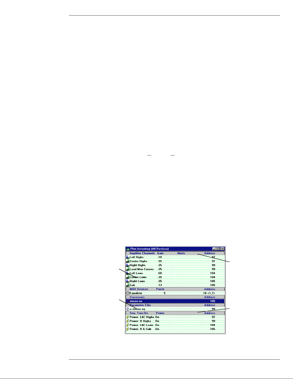
The Plan Inventory is the total collection of all devices that have been added to this plan.
The plan inventory serves as a good repository from which to copy devices when creating
logically-organized groups.
Double-click here to display
the planwide amplifier
Double-click on any device
to open its control panel.
control panel.
Right-click on any device to
pop-up a menu for device
setup or to open control
panels related to the
selected device.
Plan Inventory Window
Software Manual Page 2.1
Double-click here to display
the planwide sequential
turn-on control panel.
Page 12

NexSys v. 3.0 Crest Audio Inc.
Groups
A group is a collection of devices placed together for the purpose of common control or
monitoring. You can create a group by selecting Group | New from the menu. Any device
that can be controlled by NexSys can be added to a group. Asingle device may be added to
more than one group.
Groups exist to customize a Plan according to your specific needs. They serve as a tool to
logically organize your Plan. For example, you may create a group that contains all amplifier channels for the low frequency drivers. You may also have a group for the stage left.
There is no practical limit to the number of groups you can create.
All of the amplifiers within a group may be controlled by the group control panel. Different
group views provide console-like control arrangements for the channels in a group.
Snapshots - Plan & Group
Snapshots are a way to save NexSys control settings for later recall. A device’s current setting, such as gain, is “snapshotted” and saved under a user-defined name for instant recall
at a later time. Snapshots cover two levels, Plan and group. You can open the snapshot windows by selecting P
lan | Snapshot | Open or Group | Snapshot | Open.
Scenes
A scene is a way of saving/recalling different desktops (arrangements of windows) within
NexSys. One scene may contain the amplifier control windows for the lower level of a stadium while the controls for the upper level could be saved in a different scene. Another may
just contain the snapshot window as a means for simply controlling a complex sound system. Scenes can be saved via the scene maintenance window. This window is accessed by
the Scene button on the tool bar or from the DeskTop | Scene menu.
Event Monitor
The Event Monitor tracks system wide faults and activity and generates the Event Log. An
Event Log shows the “what and when” of events which occur while NexSys is running. The
Event Monitor can be viewed by selecting Options | Event Monitor. The Event Log can
also be saved to a file on the host computers hard disk. Once the Event Log is activated, all
critical system operation information, including date and time of the event is recorded to a
text file. You may give the Event Log a unique name to keep its data separate from other
logs.
Software Security
The security features of the NexSys program allow three levels of security access with varying privileges for each level. This feature allows the system administrator to tailor who will
have access to various control functions within the software. The Security Administrator
window can be opened by selecting Options | Security from the menu.
Event Scheduler
The Event Scheduler is a second software application supplied as a companion program to
NexSys. Event Scheduler allows almost limitless automated control of all NexSys functions. You can open or switch to the Event Scheduler by selecting Plan | Event Scheduler
from the menu. When NexSys and the Event Scheduler appear as the top two items in the
task list, you can switch between these two programs by pressing ALT + TAB.
Page 2.2 Software Manual
Page 13

Crest Audio Inc. NexSys v. 3.0
You can program the Event Scheduler to initiate tasks at a given time (computer clock) or
when some other event (such as a switch closure or a fault) takes place. A scheduled event
consists of four parameters:
• the event trigger
• the task or action to take place, i.e. what to do
• the target of the action, i.e. which device or devices to perform the action to
• number of times to repeat action & at what frequency (just once, hourly, daily...)
Load Monitoring
Systems configured with optional Load Monitoring hardware allows NexSys to perform
diagnostic impedance versus frequency testing of the load on each amplifier channel.
Audio Return
In systems where Load Monitoring hardware is installed, NexSys provides a line level
Audio Return port so that program material may be bussed to the remote control position
for audible monitoring.
MIDI Interfaces
MIDI-compliant third party devices (such as EQ’s, delays, etc.) may be controlled from
within NexSys via the optional MIDI Interface unit. NexSys can send (and receive) MIDI
patch changes from its control panel or as part of a snapshot.
Software Manual Page 2.3
Page 14

Page 15

Crest Audio Inc. NexSys v. 3.0
3. Network Topology
3.1 Amplifier Classes
NexSys hardware is broken into two general groups: components for the CKS, CKV and
CKX Series amplifiers or the “CK family amplifiers” and Professional, FCV, CC & CV
Series amplifiers or the “Pro class amplifiers”.
CK family amplifiers utilize a unique modular approach whereby both NexSys network and
Load Monitoring modules are installed in the amplifier itself. In addition, a variety of input
signal (analog and digital) processing modules are available to expand NexSys as a signal
processing system.
Pro class amplifiers are connected to the bus via a Supervisor main frame and daughter
cards; Load Monitoring also takes place via an outboard main frame and daughter card unit.
NexSys controllable signal processing modules are not available with this class.
3.2 Networks, Nodes and Buses
The NexSys network is EIA485 compliant. Each Device on the network is termed a node.
Nodes on a NexSys network include: NC-NXS modules installed in CKS, CKV and CKX
amplifiers, Hubs (NDP-JTH), MIDI Interfaces, Supervisor and Load Monitor Mainframes
(for Professional, CC/CV & FCV Series amplifiers), and the Bus Server itself.
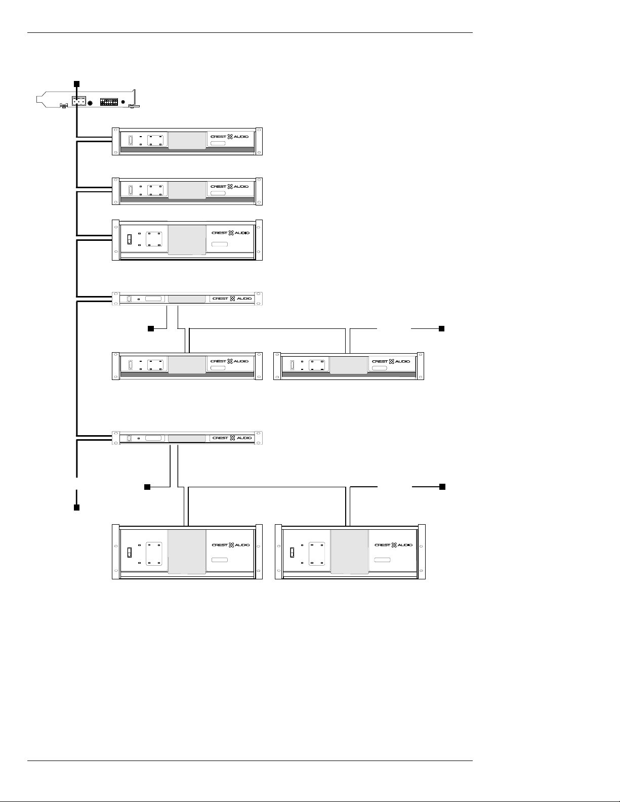
As with any network, each node must have a unique address. Valid addresses range from 1
to 111, inclusive. In the figure on the next page, an address for each node is shown outside
and next to the Device. For instance, the CKS 800 amplifier is at address 0,3.
Software Manual Page 3.1
Page 16
NexSys v. 3.0 Crest Audio Inc.
Termination
1
2
3
10
Primary Bus
On
Off
Remote
On
Off
Remote
On
Off
Remote
On
Off
On
Off
Remote
All bus wiring is twisted pair
Bus Server (in PC)
ACL
ACL
Signal
Signal
Protect
ACL
AC
Ch A
Ch B
Signal
Active
Signal
Protect
ACL
ACL
Ch B
Ch A
Signal
Active
Signal
Active
CKS 200
Professional Power Amplifier
CKS 400
Professional Power Amplifier
CKS 800
Professional Power Am
NexSys HUB
NDP-JTH
Secondary Bus
Termination Termination
Protect
ACL
AC
Ch A
Ch B
Signal
Active
Signal
45
CKV 200
Professional Power Amplifier
Amplifier
plifier
Amplifier
Amplifier
Amplifier
NexSys Hub
On
Off
Remote
Up to 32
devices
Protect
ACL
AC
Ch A
Ch B
Signal
Active
Signal
CKV 200
Professional Power Amplifier
Amplifier
20
Up to 32 devices
On
Active
Off
Termination
NexSys Hub
NexSys HUB
NDP-JTH
Secondary Bus
12
Up to 32
devices
Termination
Termination
Protect
ACL
On
Off
Remote
ACL
Ch B
Ch A
Signal
Active
Signal
CKS 1600
Professional Power Amplifier
-
2
Amplifier
Protect
ACL
On
Off
Remote
ACL
Ch B
Ch A
Signal
Active
Signal
CKS 1600
Professional Power Amplifier
-
2
Amplifier
A NexSys Network with CK family amplifiers and hubs
While a node itself can only be set with a single address, NexSys may report its address with
multiple levels or tiers. This is because multiple NexSys networks may be interconnected
using NexSys hubs or because data-concentrating devices (such as Supervisors) may reside
on the network.
Loosely defined, a bus represents a group of nodes connected together via twisted pair
cable, with a terminating resistor at each end. that are not separated by a hub. The group of
all busses that are interconnected via hubs is referred to as the network.
Page 3.2 Software Manual
Page 17

Crest Audio Inc. NexSys v. 3.0
A network may be made up of one or more busses. The bus connected to the Bus Server is
defined as the primary bus. All other busses in the network are referred to as secondary
busses and must be attached to the primary bus through a hub or data concentrator.
All nodes on the primary bus will have single-tiered addresses as follows:
Device Address
CKS 200 1
CKS 400 2
CKS 800 3
Hub (1st) 10
Hub (2nd) 20
Hubs
A network cannot support more than 32 nodes. Hubs must be used for networks larger than
32 nodes or where odd physical network runs are required. A hub has two bus connections,
one for the primary side and one for the secondary side. The bus on the secondary side of
the Hub (its secondary network) is electrically isolated from the primary bus but is still a
part of NexSys’ overall network.
Hubs expand the maximum number of nodes in a system from 32 to 1024. The number of
unique addresses is also expanded.
Nodes on a hub’s secondary side will have a “two part” address. The first address is the
hub’s primary address (i.e. the address of the hub on the primary bus.) The second address
is the address of the node on the secondary bus. In the figure, the first hub (at primary
address 10) has two CKV amplifiers attached to its secondary bus. Their addresses are:
Device Address
CKV 200 10,4
CKV 400 10,5
Similarly, the second hub (at primary address 20) has two CKS amplifiers attached to it:
Device Address
CKS 1600 20,1
CKS 1200 20,2
Notice that amplifiers “CKS 1600” and “CKS 1200” on the second hub’s bus have the same
addresses (1 and 2) as the CKS 200 and CKS 400 on the primary bus. This is acceptable
because the inclusion of a unique primary address differentiates them in the network .
Supervisors (Pro class only)
A Pro class network must have at least one Supervisor. Although the two classes of amplifiers may be combined on a single network, it is helpful to separate them for illustration purposes. Each amplifier has a two part address. The first being the node address of its
Supervisor main frame and the second being the amplifier number or Supervisor port number. There are two Supervisor ports per Supervisor daughter card. There is a one to one connection between each Supervisor port and amplifier.
Software Manual Page 3.3
Page 18
NexSys v. 3.0 Crest Audio Inc.
T ermination
1
Load Monitor (with channel numbers)
2
Primary Bus
1
3
Up to 32 devices
Bus Server (in PC)
Load Monitor
2
On
ACL
Off
Remote
Signal
Signal
All bus wiring is twisted pair
ACTIVE
POWER
Amplifier Outputs
12
ACL
CKS 200
Professional Power Amplifier
Supervisor (with port numbers)
Supervisor
12
Clip/Limit
Signal
Temp/DC
Active
-6
-6
-10
-10
-3
-3
-15
-15
-1
-1
-30
-30
-80
-80
0dB
0dB
Ch B
Ch A
Clip/Limit
Signal
Temp/DC
Active
-6
-6
-10
-3
-10
-3
-15
-15
-1
-1
-30
-30
-80
0dB
-80
0dB
Ch A
Ch B
Clip/Limit
Signal
Temp/DC
Active
-6
-6
-10
-3
-10
-3
-15
-15
-1
-1
-30
-30
-80
0dB
-80
0dB
Ch A
Ch B
POWER
24
8001
7001
Professional Power Amplifier
6001
Professional Power Amplifier
Professional Power Amplifier
Termination
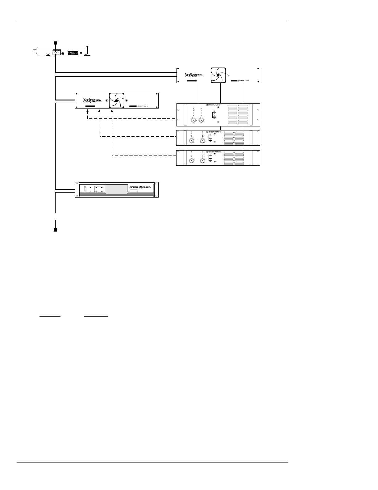
Pro class network setup diagram
The diagram above shows one Supervisor mainframe with three Professional Series amplifiers connected, one Load Monitor mainframe, and one CKS amplifier.
Each Supervisor main frame can accept up to 24 dual channel amplifiers. An amplifier
attached to a Supervisor uses the Supervisor’s address (primary) and its Supervisor port
number to specify its secondary address. NexSys would report addresses for the Devices in
this figure as follows:
Device Address
8001 1,1
7001 1,2
6001 1,24
The only time a Supervisor will appear in the software is when the system is being polled
during AutoPlan. NexSys does not need to identify the Supervisor as such; its presence is
indicated inherently by the amplifiers attached to it -- you can't "control" or monitor a
Supervisor, you can control and monitor the amplifiers.
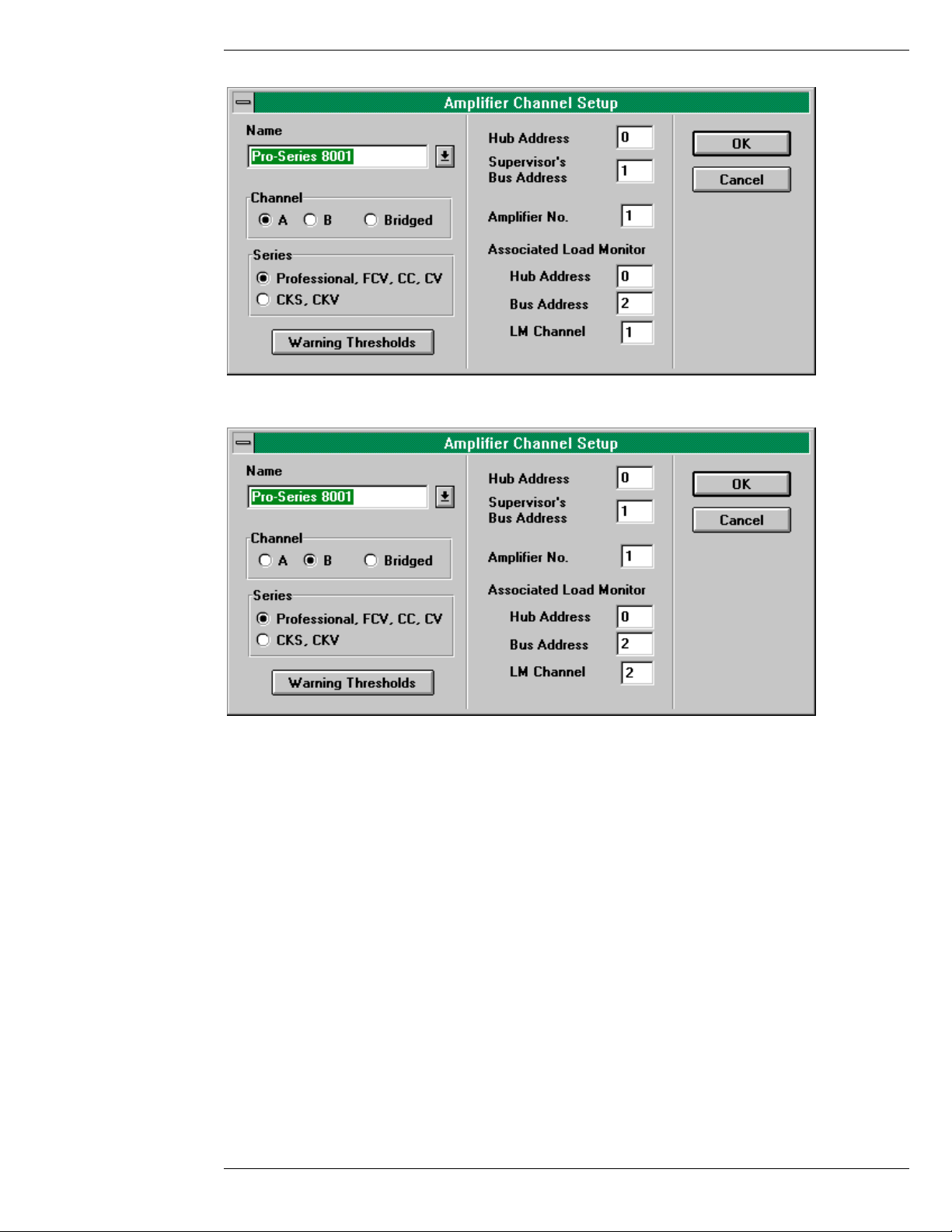
Load Monitor Mainframe (Pro Class only)
The Load Monitor is similar to a Supervisor in its transparent nature to the software. You
specify that an amplifier's outputs are connected to the channels of a Load Monitor in the
amplifier setup dialog. The setup dialogue for the amp labeled "Pro Series 8001" would look
like this for channel A:
Page 3.4 Software Manual
Page 19
Crest Audio Inc. NexSys v. 3.0
... and this set up information for channel B:
Amplifier Channel Setup Windows
Note that the Load Monitor must reside on the same network as the Supervisor. That is, it
cannot be separated by a hub.
3.3 Network Terminations & Bus Wire Type
In order to minimize data reflections, the network domain must be properly terminated at
extreme ends. Terminating a network is accomplished by placing a resistor (chosen to match
the characteristic impedance of the cable) across the twisted pair.
Crest Audio recommends using Belden 8442 unshielded twisted pair cable with 110Ω terminating resistors. Other cable may be used; however, the maximum transmission distance
may decrease due to increased distributed capacitance of the cable. Use of other cable may
also require different terminating resistors. Mixing different cable types on the same network or the use of star topologies within the same network must be avoided due to the
impedance mismatch between cables. All cables must have a characteristic impedance of
100Ω at 100kHz.
All bus connections are opto-isolated, thus eliminating any ground loops and to minimize
RF interference.
Software Manual Page 3.5
Page 20

NexSys v. 3.0 Crest Audio Inc.
3.4 Network Addressing
Hardware address settings are determined in two ways (depending on the amplifier class.)
In Pro class amplifiers, the network address is given by its Supervisor’s address. A
Supervisor is a unique network node whose address is set via DIP switches on the rear
panel. This is the primary address. The rear of the Supervisor holds up to 12 daughter cards
– each with 2 ports for a total of 24 ports. An amplifier’s secondary address is given by the
port number to which it is connected. The maximum number of amplifiers that can be connected to a network is 744 (31 Supervisors, each with 24 amplifiers.)
Pro class Load Monitor Mainframe’s network addresses are set in the same manner as
Supervisors. Load Monitors can hold up to 12 daughter cards which can accommodate 2
amplifier channels for a total of 24 amplifier channels.
CK family Power Processing amplifiers are connected directly to the network – there is no
need for Supervisors and Load Monitors. Each address is set via a hexadecimal* rotary
selector on the back of the NexSys network module (NC-NXS.) A network can accommodate 31 CK family amplifiers before a hub is needed. For systems with more than 31 nodes,
a NexSys Hub is needed. The secondary network of the hub can accommodate 31 more
nodes. So the largest CK class system would contain 961 amplifiers. Load Monitoring and
other processing functions in the CK family amplifiers use the same address as the amplifier.
* NexSys displays most addresses in decimal (Base 10). You must address
the CK family amplifiers using the hexadecimal spinwheels. A hex-to-decimal table is provided in Appendix A.
When NexSys displays or requires a number to be entered in hexadecimal
(Base 16), an ‘H’will appear next to the number. The bus server address
in the options bus server window is a prime example.
Page 3.6 Software Manual
Page 21
Crest Audio Inc. NexSys v. 3.0
4. Bus Server Installation and Connection
4.1 Installing the Bus Server Card
The Bus Server Card (NS-BUS-1) is an 8-bit ISAexpansion card which requires installation
in a vacant slot inside the NexSys host computer . If you are unsure how to insert an ISAcard
Device inside your computer, please consult a qualified computer technician for assistance.
Otherwise, follow these instructions to ensure a safe and speedy installation.
1. Make sure your computer is switched off and disconnected from the electrical
mains. Be sure to use an anti-static mat or other device to reduce the risk of
component failure due to static discharge.
2. Open the computer case & locate a vacant ISA card slot.
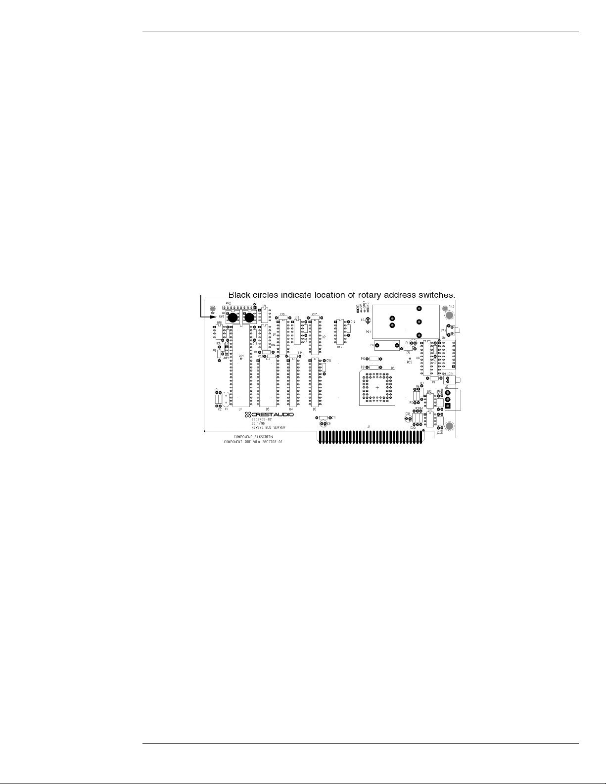
3. Remove the mating Phoenix connector from the Bus Server card. The card was
configured and tested prior to leaving the factory. However, shipping and handling may have caused the rotary address switches to shift so verify that they
are set to F (HI) and 0 (LOW).
Bus Server Card rotary switch locations
Carefully insert the Bus Server card into the slot ensuring that the edge connector is properly seated and that the Phoenix connector clears the computers rear
panel.
4. Reinstall the outer casing.
5. Affix the NexSys network wire into the mating Phoenix connector and insert it
into the Bus Server card. (See the section Connecting the Bus Server to the
NexSys Bus, below.)
6. Reconnect the AC mains
Connecting the Bus Server to the NexSys Bus
A 3-pin, 5mm removable terminal block (Phoenix Contact 17.5.4.46.5 or equivalent) connector is located on the back of the Bus Server card for connection to the data network. Only
the positive (pin1) and negative (pin2) pins of the connector are used. The third, ground pin
is normally left open. (See Appendix C for a detailed view of Bus Server connections)
Network polarity must be observed when connecting the Bus Server or any other network
device to a NexSys network. If reversed, the network will not operate and NexSys will not
be able to communicate with any network devices.
Software Manual Page 4.1
Page 22
NexSys v. 3.0 Crest Audio Inc.
4.2 Communicating with the Bus Server
The Bus Server resides at an I/O address range in your PC. Its base address (the beginning
address of the range) is referred to as the Bus Server’s I/O address, or I/O address for short.
This address is set using the DIP switches positioned on the Bus Server’s mounting bracket (at the back of the PC). The default address used for Bus Server testing at the factory is
380 Hex. In some instances this address may be in partial or total conflict with other cards
that are installed in the host computer. For example, Ethernet network and sound cards all
have I/O addresses that may use the same address (in entirety) or may partially over lap. In
these instances the base I/O address must be moved to a vacant address. Some common free
I/O locations and the corresponding DIP switch settings for the Bus Server card are listed
in the Dip Switch Settings (Appendix C) at the end of this manual.
Changing the Bus Server’s I/O Address
The Bus Server’s I/O address as given by its DIPswitches and its setting within the NexSys
software must agree. Changing the I/O address involves the following steps.
1. Set the Bus Server DIP switches to the desired
address.
(See Appendix C for dip switch settings)
2. Press the Reset button on the Bus Server mounting
bracket in order for the new address to take effect.
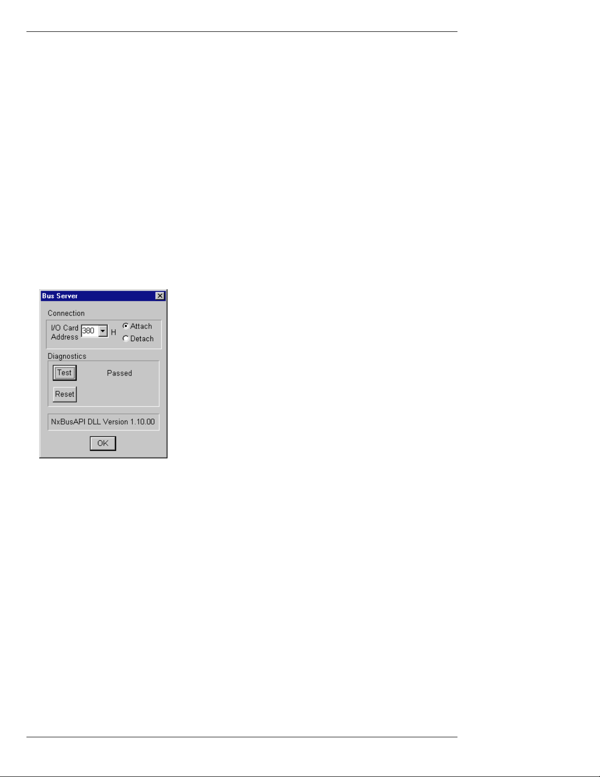
3. NexSys must be informed of the address change -open the Bus Server dialog (see the figure at left) by
selecting Options | Bus Server from the menu.
4. Select or type in the new address in the I/O Address
field.
5. Press the Test button (see note below)
Bus Server Dialog Window
6. If the tests pass, NexSys can successfully communicate
with the Bus Server card. Select “Attach” so that
devices within NexSys can communicate.
7. If the test fails, you need to select a new I/O address at
the Bus Server’s DIP switches and repeat the entire
process. (Rebooting the computer may also be
required in some instances.)
A note on the Bus Server diagnostics...
Pressing the Test button starts one of two tests. The first, the signature test, simply “looks”
to see if the Bus Server card is present. If it is, NexSys prompts you with a second, more
extensive test. The second is a test of the full I/O range the Bus Server will use. Warning:
of necessity ”Test Full I/O” is extensive and, if conflicts are found, it could crash your computer. Save your work prior to conducting the full range test.
Once you’ve established a connection with the Bus Server, save the plan so that the new setting will be in effect next time.
Page 4.2 Software Manual
Page 23

Crest Audio Inc. NexSys v. 3.0
5. The Toolbar & Menus
5.1 Toolbar
The toolbar offers quick access to more frequently used NexSys functions. The diagram
above identifies each functional grouping within the toolbar.
• Scene Selector - a drop down selection box to quickly load a new scene (i.e.
desktop).
• Scene Maintenance - brings up the Scene Maintenance dialog. You can create
and delete scenes in this dialog.
• Plan Snapshot Control - snapshot control for plan-wide snapshots.
• Plan-wide Amplifier Control Panel
• Group Selector - allows you to quickly open a group that is in the plan but not
on the screen.
• Group Views - a group must be the active window (a window with a highlight-
ed title bar) in order for these buttons to be enabled. Once they are enabled,
these buttons will display the group as a list of devices (list view) or one of the
various console views.
• Plan Inventory Selections - buttons that will open one of the plan inventory
windows.
Software Manual Page 5.1
Page 24

NexSys v. 3.0 Crest Audio Inc.
5.2 Menus
NexSys 3.0 menu hierarchy.
Complete listing (with a brief description) of all menu commands is located in Appendix B.
5.3 Right Mouse Menus
In many places throughout NexSys, right clicking on an object displays a pop-up
menu relating to that object. Look for this icon (shown at left) throughout this
manual to indicate that a right mouse selection is available.
Page 5.2 Software Manual
Page 25

Crest Audio Inc. NexSys v. 3.0
Software Manual Page 5.3
Page 26

Page 27

Crest Audio Inc. NexSys v. 3.0
6. Building a Plan
A NexSys Plan is made up of user-defined devices, groups, snapshots, scenes, and settings.
The Plan is stored on disk as a collection of data files organized in a subdirectory of the
NexSys program directory. Plan files have a default extension of “*.nx”. Plan files themselves are normally stored in the root NexSys directory which defaults to C:\NEXSYS.
Before proceeding, ensure you have a valid network connection. Refer to Section 4.2 on
Communicating with the Bus Server. Of course, if you’re not connected to a system you
may still build a plan, you just won’t have any communication with the devices you create.
6.1 Making a New Plan
Create a new Plan by selecting P
lan | New from the menu. The Plan Name dialog will
appear (see figure below) prompting you to name the Plan and select its location. Enter the
new name for the Plan file (CONVCTR2.NX is used for examples in this manual) and press
OK.
A note about directories and plans:
Most times you will simply save the Plan files (*.nx) to the NexSys root directory
(C:\NEXSYS). Or- you could elect to save it to a different drive or directory. In either case,
the Plan file will be saved to the specified directory and a subdirectory will automatically be
created with the same name as the Plan. The subdirectory is where NexSys will store the
various data files that are specific for that Plan.
Plan Name Window
6.2 AutoPlan
If you’re starting with a new system (all hardware connected), using AutoPlan is the easiest
method to build a Plan. AutoPlan polls the network and creates a list of every device it finds.
If you are adding devices to an existing Plan the AutoPlan Append feature will add the
‘newly found’devices to the existing device Inventory. From here it is a simple task to drag
and drop the new devices into any logical groups you create (see Chapter 7, groups.) Start
AutoPlan by selecting Option | AutoPlan from the menu.
Software Manual Page 6.1
Page 28

NexSys v. 3.0 Crest Audio Inc.
There are two principal components to the AutoPlan window:
a list of the network nodes and
devices AutoPlan finds is on the
left and a progress report showing the current state of the
search phase is on the right.
Each network address that is
found to have an active device
present is listed. Most times the
device will be an amplifier. Any
other devices, such as signal
processors sharing the same
address are shown as well.
NexSys Autoplan Window
When AutoPlan finishes searching for devices you will have three choices:
• Append - AutoPlan will add the devices it found to the Plan Inventory if they
aren’t in the inventory. Devices added by AutoPlan are named by their model
type.
• New Plan - Create a new plan based upon AutoPlan’s findings.
• Cancel - No changes to the plan will take place.
AutoPlan can also be a useful system troubleshooting tool. This is because AutoPlan searches for devices in phases, namely:
Bus device Search Phase - Searches for devices directly connected to the network,
including: the Bus Server, NC-NXS modules, Hubs,
Supervisors, Load Monitors and MIDI Interfaces.
Amplifier Search Phase - Searches for amplifiers containing the NC-NXS module
in the case of CK family amplifiers and those connected to Supervisors for NexSys Pro.
Amplifier Type Search Phase - Identifies the amplifier model.
CK Module Type Search Phase - Shows the type of input/output modules contained in a
CK family amplifier.
Troubleshooting an inoperative network follows these phases. If NexSys can’t find the Bus
Server, it surely won’t be able to find any amplifiers attached to the network. Similarly, if a
Supervisor does not report during AutoPlan, any amplifiers connected to it will not be
found.
6.3 Manually Adding devices
Devices can be manually added to a plan at any time by selecting device | New from the
menu and then selecting the type of device you would like to create. A setup dialog will
appear in which you can enter the name, address and any other device-specific data.
To manually add an amplifier channel to the plan:
1. Open the Plan Inventory window or the group to which you want to add the
Page 6.2 Software Manual
Page 29

Crest Audio Inc. NexSys v. 3.0
amplifier.
2. Make sure the Plan Inventory window (or the group window) is the active window. An active window is the one with the highlighted title bar.
3. Select D
evice | New | Amplifier from the menu.
4. Fill in the Setup dialog (see section on device Setup) and select OK.
5. The amplifier channel you created should now appear in the Plan Inventory
(and the group window, if that was the active window)
Although a somewhat more labor intensive process than AutoPlan, adding devices manually can prove useful in some situations. One situation is where the equipment has yet to be
installed. Under these circumstances, you are still able to manually build a plan with no
hardware connected. The plan can be as detailed as desired, complete with logically named
devices, organized groups, control settings, and even snapshots. When complete save the
plan to disk and copy it to the system’s PC.
6.4 Saving The Plan
As with any computer program, save your work often especially when making extensive
changes. To save your plan, just choose Plan | Save from the menu.
To save a plan under a different name (or to create a copy of the current one,) choose Plan
| Save As.
6.5 Plan Inventory
The Plan Inventory shows all of the devices that are part of the plan, including any device
added manually or by AutoPlan. The Plan Inventory categorizes devices by type. Within a
category, devices are sorted by their bus address.
You can open the Plan Inventory window by selecting Plan | Device Inventory or by pressing one of the Plan Inventory toolbar buttons. The basic plan inventory window shows all
devices in the plan. Limited views of specific types are also available.
All devices - Shows the entire plan inventory.
Amplifier Inventory
MIDI device Inventory
Sequential Turn-On Module Inventory
DSP Module Inventory
Crossover Module Inventory
Equalizer Module Inventory
List of all devices that are experiencing a fault.
Software Manual Page 6.3
Page 30

NexSys v. 3.0 Crest Audio Inc.
Double-click here to display
the planwide amplifier
Double-click on any device
to open its control panel.
Right-click on any device to
pop-up a menu for device
setup or to open control
panels related to the
selected device.
Plan Inventory Window
control panel.
Double-click here to display
the planwide sequential
turn-on control panel.
The plan inventory serves as a good repository from which to drag and drop devices to logically-organized groups. It is also a convenient place from which to set up each device in
the system.
6.6 Device Setup
A device may be configured by opening its setup dialog. This task can be accomplished in
one of three ways:
• In the process of creating a new device, Device Setup is automatically called.
• After having selected a device in the Plan Inventory or a group, select Device
| Setup from the menu.
• Right click on a selected device and select Device Setup from the
pop-up menu (below).
Device Setup Menu
A Cancel button appears on all Device Setup dialogs. Pressing it discards all setup changes
made to the device. Two parameters are common to all devices: the name of the device and
its address. These items are covered first. More specialized setups are then covered on a
device by device basis.
Changing the Device’s Name
You can enter a device’s name by typing in the Name combo-box. By pressing the down
arrow in the combo-box, you can choose a name from among the last few entered. This is
especially useful for repetitive names where perhaps only a single character is different.
Page 6.4 Software Manual
Page 31

Crest Audio Inc. NexSys v. 3.0
Changing the Device’s Address
A device address is based upon the device’s network node address. An address may be single- or two-tiered depending on its connection. Devices connected to a Hub or Supervisor
will always be two-tiered. Devices connected directly to the primary bus will be singletiered. Adiscussion of Networks, Nodes and Buses (Section 3.2) has been presented and is
worth reviewing if you’re not familiar with these concepts.
The highest acceptable node address is 111 decimal (see Appendix A for a decimal-hexadecimal conversion table). This applies to all network devices; including Hubs, Supervisors,
Load Monitors, MIDI Interfaces, and CK family amplifiers.
The lowest valid node address is 1 for all network devices. Note that a Hub address of 0
should be used as a placeholder for devices where no Hub is present.
CK family Amplifier Setup Window
Specify which channel of
the amplifier at this
address is "Balcony
Left." If the amp is
bridged, select it and
only make one channel
for that amplifier.
A Supervisor has 24
communication ports
available. Valid entries
are from 1 to 24.
If an optional Load
Monitor is connected to
the output of this
channel, enter the Load
Monitor’s address here.
... and enter the channel
number to which the amp’s
output is connected, here.
Valid entries are from 1 to
12.
Pro Class Amplifier Setup Window
After setting up a device and selecting OK,
you will see the communications alert icon… .
Software Manual Page 6.5
Page 32

NexSys v. 3.0 Crest Audio Inc.
If that device is found by NexSys at the address you selected, the alert will disappear shortly . If the alert remains for several seconds, there is something wrong with the address selected, the device or the network itself.
Duplicate address or out of range address are the most common reasons
for communication errors.
Enter the MIDI Interface's
network address here.
The MIDI Interface has
two MIDI Outs, select
which one the MIDI device
is connected to here.
MIDI devices at this
channel will receive
patch changes from this
NexSys MIDI device.
MIDI Device Setup Window
6.7 Venue Bitmap Background
If you have a bitmap file (Windows Paintbrush format .BMP) of the system or venue, you
can place this as the background of the Plan to serve as a graphical reference. Group icons
can be located on top of the bitmap graphic as desired and saved as part of a Scene. Once
saved, all icons will always be located in the same position when they are minimized. If you
would like your venue to be displayed with a “transparent background,” use cyan as the
background color in your bitmap. NexSys will replace cyan with the background color of
the window (i.e. the application workspace color.) The red, green and blue (RGB) components of cyan are 0, 255 and 255, respectively.
A venue bitmap can use a lot of memory. For example, a 256 color, 1024x768 pixel bitmap
uses almost 1 megabyte of memory. If your system has a limited amount of RAM (such as
8MB or less) and a large number of devices, you may not want to use a venue bitmap. The
same holds true for other Windows programs such as screen savers, elaborate desktop
themes, etc.
Venue Bitmap Background Example
Page 6.6 Software Manual
Page 33

Crest Audio Inc. NexSys v. 3.0
7. Groups
NexSys groups are designed to facilitate the control of amplifiers and other devices. Devices
that make sense to control and monitor together can be organized by moving them to the
same group.
For example, if we have a two-way stereo system with two amplifiers (left HF, left LF, right
HF, right LF), we might want to make groups of Left & Right High Frequency plus Left &
Right Low Frequency . That way we can control the amplifier channels together in these logical groups. Other examples of what might be a logical group are Concourse Level, Zone 1,
Delay Speakers, etc.
7.1 Creating a group
A group is created by selecting G
roup | New from the menu. You are then prompted to
name the group as shown here. Valid characters for group names include all alphanumerics,
spaces, and keyboard symbols.
There is no limit to the number of groups you
can create. However, there is a practical limit
beyond which adding groups adds complexity
without increasing functionality. It may confuse an operator to control a single device
from many different points within the soft-
New Group Dialog Box
ware. [Try starting with a lean plan and gain
some operating experience before creating
numerous groups.]
It is also possible for a device to be in more than one group. Remember, groups are for
access and control convenience and not only physical location.
7.2 Renaming a Group
You can rename a group as simply as you created it. First make sure that the group window
is active (i.e. its border is highlighted.) Then, select Group | Setupfrom the menu. You will
be prompted to change the name of the group. Press OK to make the change or Cancel to
discard it.
7.3 Deleting a Group
Make sure the group window you want to delete is the active window (by selecting it).
Select Group | Delete Groupfrom the menu. Awarning will appear to verify that you real-
ly want to delete the group.
7.4 Adding Devices to the Group
Most often, you will add devices to your group that already appear in the Plan Inventory.
Adding devices in this case is simply a matter of dragging them from the inventory and
dropping them into the group. Devices can be moved or copied from one group to another.
Note that devices can only be copied from the Plan Inventory, they cannot be moved from
it.
Software Manual Page 7.1
Page 34

NexSys v. 3.0 Crest Audio Inc.
Moving a Device
Ensure that the destination group window is open. Select the device from the source group
window (or the plan inventory). Press and hold the left mouse button. While moving the
cursor over a group window you will see it change to an amplifier icon:
This indicates that the device may be dropped into the group beneath the cursor .
In areas where the device cannot be dropped, the cursor will look like this:
Once the cursor is over the desired destination, release the mouse button. The
device will appear in the destination group and will be removed from the source
group. Remember, if the source group was the Plan Inventory, it will be copied,
not moved.
Copying a Device
The technique for copying a device from one group to another is virtually the same as moving a device. The only difference is that before the left mouse button is released, press and
hold the CTRL key. This will copy the devices (instead of moving them) to the destination
group. Be sure to wait to release the CTRL key until after the left mouse button is released.
Once again, with regard to the Plan Inventory, all you can do is copy from it. Holding the
CTRL key down to copy devices from the Plan Inventory is unnecessary.
Selecting Multiple Devices
Multiple devices may be moved or copied at one time. Select more than one device in the
source group or Plan Inventory by holding down the shift and/or control keys.
To move or copy consecutive devices, click on the first device with the left mouse button.
Then, while holding the Shift key down, select the last device in the block. Once the block
is selected, drag it to the destination (as explained above.)
To move or copy non-consecutive devices, click on each device while holding the CTRL
key down. When complete, drag the devices to the destination (as explained above.)
You may combine the two techniques above to move or copy both consecutive blocks of
devices and non-consecutive ones. Just be sure to hold the CTRL key down during the
entire selection process. Hold and release the SHIFT key to establish as many consecutive
blocks as needed.
Remember, you can drag and drop (copy) from the plan inventory to a group, but
the same drag and drop (without holding the CTRL key) from one group to
another will move the item, not copy.
Page 7.2 Software Manual
Page 35

Crest Audio Inc. NexSys v. 3.0
7.5 Quickly Opening a Group
You can quickly open a pre-established group with the group
selection tool on the toolbar. Pressing the down arrow presents an alphabetical listing of all of the groups in the plan.
Select the group you want to open from the list.
Group Selection Tool
7.6 Group Views
Groups may be viewed in two principal formats: list and console. The list view is the most
comprehensive of the views. It shows the channel name, amplifier address, current gain
(including mute/solo indicators) and amplifier faults. The other four views are console-like
control views where each channel is represented by a vertically oriented module. They range
from having all controls and readouts to just the VU and temperature readouts.
Group List View & the Plan Inventory
The most comprehensive view a group window can display is the list view. This is also the
only view the Plan Inventory offers. Each device appears as a separate line with an icon representing the type of device, its name, any relevant parameters, any faults, and the address.
The following example has a group entitled “Stage Right.” Stage Right is a group containing the B channels of three CKS series amplifiers and their corresponding sequential turnon devices. The figure below breaks down the components of the list view.
Amp channel's current gain Mute/Solo
Device Name
Press this button to open the
group's snapshot window.
Press this button to open the
group's amplifier control panel.
indication
("M" or "S")
Alerts for each device. Here,
"Right Lows" is clipping.
Double-click on any device
to open its control panel.
Right-click on any devce to
open its pop-up menu.
Device address
Double-click here to open
the sequential turn-on
control panel for this
group.
Power state of sequential
turn-on device.
Group-wide alert panel.
Alerts are summed for the
entire group and displayed
here.
Group List View
Software Manual Page 7.3
Page 36

NexSys v. 3.0 Crest Audio Inc.
As you can see from the figure, the amplifier channels are grouped together and the sequential turn-on devices are grouped together. In general, list view separates devices by type.
All device types display basic information such as their name, alerts, and address. Some
devices, especially amplifiers, present additional information. Here is device-specific information you can expect to see:
• Amplifier channels show their current gain, whether they are muted or soloed,
and any of seven different faults.
• Sequential turn-on devices show their switch position.
• MIDI devices show the last patch change sent.
• NC-DSP modules show the current DSP program or algorithm that is running
in the module.
Group Console Views
There are four other views in which a group of amplifier channels can be displayed. In the
console views, each channel is represented as a vertical module showing input and output
VU, temperature meters, faders, mute & solo buttons, phase and audio return (monitor) buttons. Each of these alternative views for the Stage Right example group follow.
Full View
No VU meters
VU meters only
Mute/Solo only
Page 7.4 Software Manual
Page 37

Crest Audio Inc. NexSys v. 3.0
Because of its compact format, it is sometimes difficult to know which amplifier channel a
module refers to. Balloon help alleviates this problem. Place and hold the mouse cursor in
the title bar of the module and a balloon will appear providing the amplifier’s full name,
address and channel. When the mouse is moved, the address information is no longer displayed.
Balloon Help example
Software Manual Page 7.5
Page 38

Page 39

Crest Audio Inc. NexSys v. 3.0
8. NexSys Faults, Alerts & Events
NexSys is always monitoring the system for faults. Faults or alerts are reported on screen
and are sent to the Event Monitor/Log.
8.1 Alert Panels
The bottom of the NexSys window and the bottom of every group window (in list view)
contain panels which illuminate alert icons when a fault is present. Next to each alert icon
is a count representing the number of devices (or amplifier channels) that are experiencing
the fault. For the alert panel at the bottom of the NexSys window, this count is representative of all devices in the plan. For the alert panels at the bottom of group windows, the count
represents only those devices contained in the group.
Communications Alert - NexSys is unsuccessful in its attempts to communicate with
devices showing this fault.
Thermal Protect Alert - amplifier channels with
this alert are in thermal protect.
DC Protect Alert - amplifier channels with this
alert are in a DC protect state.
IGM Alert - Instantaneous Gain Modulation circuit has activated for amplifier channel with this
fault.
Clip Alert - amplifier channels with this alert
have exceeded their clipping threshold.
User Thermal Protect - amplifier channels with
this alert have heatsink temperatures above
their user-specified threshold.
Alert Panels (above) and icons (below)
While alerts are “summed” on these alert panels, they are individually represented by the
following icons in list view.
Communications Thermal Protect DC Protect
User Thermal Warning Clip Event IGM Event
Power Alert - While not a true fault, this alert shows that the CK family amplifier is
off. When this alert appears simultaneously with the Communications alert, it is likely that
the amplifier has no mains power supplied. Power alert is exclusive to CK family of amplifiers. It does not appear on Pro class amplifiers. Power loss in that class is typically indicated by a Communications alert.
Software Manual Page 8.1
Page 40

NexSys v. 3.0 Crest Audio Inc.
8.2 Amplifier Warning Thresholds
The warning thresholds window may be accessed by pressing the Warning Thresholds button in the Amplifier Setup (Device | Setup) dialog. User thermal temperature, IGM and
clipping are user-definable thresholds.
User Thermal-- When the heatsink temperature
exceeds this threshold the user thermal fault, is
illuminated. The default is 60°C.
IGM (Instantaneous Gain Modulation) -- When the
amplifier has to attenuate the input signal to prevent hard
clipping. If the number of IGM events occurring in the
time allotted exceeds the threshold then the IGM alert is
illuminated. The default is 10 IGM events in 10
seconds.
Clip-- If the amplifier clips more times than the
threshold within the time allotted, the clip alert is
illuminated. The default is 10 clips in 10 seconds.
Amplifier Warning Control Window
8.3 Event Monitor and the Event Log
The Event Monitor and Event Log keep a record of all NexSys system events with a date
and time stamp. These events may include hardware faults, actions initiated by the Event
Scheduler, user log on/off and load monitor results. The Event Monitor is a window within
NexSys while the Event Log is a text file that may be saved to disk. Windows word processing programs such as Wordpad, Write or Notepad may be used to edit or print the Event
Log.
Opening the Event Monitor
Select Options | Event Monitor | Openfrom the menu to open the event monitor window.
The Event Monitor is always recording events to its internal buffer which can hold approximately 600 events in memory. Since it is a memory based buffer, when the program ends
or when it overflows the recorded events will be cleared. If you want a permanent record
(i.e. saved to disk) of events, then enable the Event Log.
Event Log Setup
The Event Log, once activated, will create a text file which is an exact record of all events
that have taken place since the time the log was activated. You must specify a file name for
the Event Log. Do so by selecting Options | Event Monitor | File... from the menu. Once
a file is selected, turn on the Event Log by selecting Options | Event Monitor | File On
from the menu. Similarly, select Options | Event Monitor | File Off to turn it off.
Page 8.2 Software Manual
Page 41

Crest Audio Inc. NexSys v. 3.0
You can print or review the Event Log by opening the event log file from a word processor
such as Word, Wordpad or Notepad. You may also use these programs to create additional
notes within the body of the file. This is helpful in adding system notes to the event file to
document such things as routine system maintenance, addition of devices, transducer
replacement, etc.
Software Manual Page 8.3
Page 42

Page 43

Crest Audio Inc. NexSys v. 3.0
9. Controlling Amplifiers
9.1 Amplifier Controls
Double clicking on an amplifier channel in list view (in a group or in the Plan Inventory)
will open its control panel. Selecting Device | Control from the menu is another way to
open a control panel. The figures below show the single amplifier control panel. Variations
of this control panel appear in the group console view, the most comprehensive of which is
depicted in the figure on the right. Note that the descriptive callouts in the figures below
apply to both variants of the control panel.
VU’s
Input Level (on left) &
Output Level (on right.)
+1 dB
Current gain.
+10 dB
Continuous
Hand cursor constrains
the mouse from moving
off of the fader until the
mouse button is
released.
Mutes this channel.
Solo’s this channel by
muting ALL other
channels in the plan.
Single amplifier control panels
Audio Return Monitor (for systems
with optional load monitoring)
Heatsink Temperature
-10 dB
-1 dB
Polarity
Double-click the Heatsink
Temperature to change it
between Celsius and Fahrenheit.
Amplifier Level Control
Each amplifier channel’s attenuator operates within a range from no attenuation (0dB) to full
attenuation (-83dB). For convenience, the fader functions in three ways. The fader’s “knob”
or “thumb” itself may be grabbed and continuously raised up and down. For quick and large
steps, clicking in the area above or below the thumb will change the level in 10dB increments. For finer 1dB steps, click the arrows at the top and bottom of the fader.
Pressing the left mouse button on the fader changes the cursor to a hand. This indicates that
the cursor cannot be moved off of the fader until the left mouse button is released -- preventing undesirable gain changes from occurring accidentally.
Amplifier Mute Control
Pressing the mute button will fully attenuate the channel. Releasing the mute button will
restore the level to that shown by the fader. Achannel may have been muted by some other
object in NexSys (see Section 9.4 on Control Hierarchy .) If so, pressing the mute button will
unmute it. This is because NexSys gives control changes at the amplifier control level the
highest priority. Therefore, a channel that has been muted at the amplifier cannot be unmuted by a group or the plan.
Software Manual Page 9.1
Page 44

NexSys v. 3.0 Crest Audio Inc.
Amplifier Solo Control
Soloing a single channel is a useful troubleshooting tool. By pressing the solo button, all
other channels in the plan will mute, leaving this channel as the only audible one. As its
name implies, only one channel may be soloed at a time. Pressing another’s solo will mute
the first channel soloed and solo the second.
Although useful for troubleshooting, an inadvertent solo while the system is in use can put
the operator in an embarrassing situation. To prevent this situation Solo buttons may be
defeated by enabling the Solo Safety (see Section 9.5.) Solo Safety can be enabled or disabled from the menu by selecting Options | Solo Safety.A word of advice; keep your job
- engage solo safety during regular operation.
Amplifier Polarity
The polarity control, labeled “Ø ” will invert the polarity of the channel.
Audio Return
Audio Return allows system operators at the control position to “listen in” to program material delivered to remote locations. A line level signal of the output of each amplifier channel is made available on Load Monitor-equipped systems. The audio return lines from several amplifiers can be bussed together and routed to a central control position. (Since the
signal is line level, a monitor amplifier and speaker will also be required.)
To enable a channel’s audio return press its monitor button, labeled “monit.” This button
can be found in the group console view.
Only one channel within a system may be monitored with audio return at a time. To monitor a different amplifier, simply select the monitor button on that amplifier. The original
amplifier monitored will automatically be deselected.
CK family amplifiers have a Phoenix style connector on the NC-SLM Load Monitor module which brings a line level signal out of the amplifier. With Pro class amplifiers, Audio
Return is available at a barrier strip on the rear panel of the Load Monitor main frame.
VU Meters
Each amplifier channel’s VU display contains two meters: input and output level. Both
meter’s scales can be changed and both meters show peak hold. The output meter’s peak
hold indicator turns red when the amplifier clips.
Output Peak Hold (green) &
Input Peak Hold
Input Scale. Double-click in this
area to cycle it through 4 scales:
· 0 to .5V
· 0 to 1V (shown)
· 0 to 100V
· 0 to 200V
Input Meter Output Meter
Clip Indicator (red)
Output Scale. Double-click in this
area to cycle it through 3 scales:
· -50 to 10dB from rated full scale
voltage (shown)
· 0 to 100V
· 0 to 200V
Page 9.2 Software Manual
Page 45

Crest Audio Inc. NexSys v. 3.0
9.2 Related devices
When pointing to a device, right clicking will show a menu of related devices those devices sharing the same address. In a CKS amplifier, there may be a
crossover, a load monitor, and a sequential turn-on control as well as the two
amplifier channels. Each is a separate device as far as NexSys is concerned but all
appear on the right-button menu. For instance, right-clicking on CH A shows this related
device menu:
Related Device menu
9.3 Group & Plan Amplifier Control Panel
When in list view, a group level control may be accessed by clicking the group con-
trol panel button at the bottom left of the group window. When in console view, the
left most module is the group control panel. The Plan amplifier control panel is accessed
by the fader button on the left of the toolbar (at the top of the NexSys window.) To open
these controls from the menu select Group | Control and/or Plan | Control.
The Plan & group amplifier controls are very similar. In fact, if you think of the Plan itself
as the largest group available in NexSys, they are identical. So in the following discussion
about how they operate what is said about one applies to the other -- only their scope is different.
Group/Plan Level
The group plan control is pictured here. Notice that the fader ranges from
+83dB to -83dB. It is a relative level to the amplifiers in its group. Positive
changes here will have the same magnitude increase for every amplifier channel in the group. A negative change here will decrease each amplifier channel
level in the group by the same amount. For instance, if the amp is set to -10,
and the group level is raised +5, the amp level will increase by 5dB to a level
of -5.
Group and plan level settings are not saved. They are simply relative controls.
However, the changes they have upon the amplifiers they control are saved in
snapshots and in the plan itself.
Group/Plan Level Control Panel
Group/Plan Mute
Pressing the group mute button will mute all of the amplifier channels in the group. Pressing
it again, will unmute all of the channels that the first action muted. Remember, NexSys treats
the amplifier channel with the highest priority. So if you have purposefully muted a single
amplifier channel within a group, unmuting the group will not override that channel’s mute.
These different conditions are conveyed by the “LED” indicator next to the group mute button.
Software Manual Page 9.3
Page 46

NexSys v. 3.0 Crest Audio Inc.
A red group mute LED indicates that all channels within that group are muted. A yellow
LED indicates that some channels within the group are muted. Agray or dimmed LED indicates that no channel in the group is muted.
9.4 Control Hierarchy
A single amplifier channel may be controlled from different points within
NexSys. Double clicking on the channel's
name within the inventory window will
open its control panel. This control panel is
the most direct way to control a channel
but there are other ways as well.
In the least complicated scenario, channel
"alpha" is part of the Plan inventory and no
groups have yet been defined. There are
two methods to change alpha's gain
(excluding snapshots): 1) directly via its
control panel, and 2) relatively, by moving
the Plan fader. The relative gain changes,
positive or negative, made at the Plan fader
will be added to or subtracted from the
alpha channel's current gain.
Control Hierarchy Examples
Now assume that alpha is also in a group named “Group 1.” The group fader is another way
of changing alpha's gain. It operates in the same manner as the Plan fader. What is important to note is that the Plan fader has no effect on the group fader . They are at the same level
of control hierarchy.
The following two diagrams depict even more complicated scenarios (though ones quite
likely to occur in a real system). The first diagram shows that there are three channels in the
Plan, "alpha," "beta" and "gamma" and two groups, "group 1" and "group 2." Group 1 contains channels alpha and gamma. Group 2 contains beta and gamma. The second diagram
shows the controls for each channel as well as the group and Plan faders. The group controls and the Plan control do not affect each other but do affect the channels.
Page 9.4 Software Manual
Page 47

Crest Audio Inc. NexSys v. 3.0
Control Hierarchy Diagram
9.5 Solo Safety
During system testing it is often useful to solo a particular amplifier
channel. However, during a performance, soloing one amp channel
and muting all others is generally not a good thing to do. Enabling
the solo safety prevents amplifiers from accidentally being soloed.
Solo safety can be toggled on and off by selecting O
ptions | Solo
Safety from the menu.
Solo Safety Toggle
Software Manual Page 9.5
Page 48

Page 49

Crest Audio Inc. NexSys v. 3.0
10. Snapshots
A snapshot is a record of device settings. Settings include levels, mutes, polarity, solo’s,
MIDI patches, NC-module parameters, etc. Once saved, the settings in a snapshot can be
instantly recalled at a later time.
There are two levels of snapshots: one for the entire plan and one for a group .
The snapshot records the control settings of the devices in its domain (either plan or group.)
Snapshots are created, deleted, edited, and updated through the snapshot window.
10.1 Inserting a New Snapshot
The first step in creating a snapshot is to make the system changes you want to snapshot.
Once (plan and/or group) settings have been made, access the snapshot window by select-
ing P
lan | Snapshot | Open or Group | Snapshot | Open from the menu. Note that to
access a group snapshot, you must have the group window open and active before selecting the pull down menu. Alternatively, just press the Plan Snapshot button on the NexSys
toolbar or the Group Snapshot button at the bottom left corner of the group window.
Right clicking on the snapshot window will open a pop-up
menu like the one to the left. Pressing the Edit button at the
bottom of the snapshot window will do the same thing.
Select Insert from the menu and an Insert
Snapshot dialog will appear as shown in
the figure. Label the snapshot in the
Name box and assign it a sequence number. Click OK. To insert another snapshot, make the changes you want to the
devices and then repeat the steps outlined
above.
Insert Snapshot Dialog Box
10.2 Recalling a Snapshot
Once saved, snapshots can be recalled in several ways. Double clicking on a snapshot recalls
it. This snapshot is considered active and is denoted by a black arrow to the left. The active
snapshot is defined as the last one that has been recalled. The Up/Down buttons sequentially recall snapshots. The Down button recalls the next snapshot in the sequence. The Up button recalls the snapshot above the active one. The snapshot list circular, pressing Down at
the last snapshot will recall the first. Similarly, pressing Up on the first will recall the last.
Software Manual Page 10.1
Page 50

NexSys v. 3.0 Crest Audio Inc.
The presence of an active snapshot does not guarantee the system is still configured as that snapshot was saved. The operator may have made changes since
the snapshot was recalled. In which case, the system would no longer be in the
state indicated by that snapshot.
Double-click on a
snapshots name to recall
a snapshot directly.
Arrow Indicator marks the
active snapshot (the last
snapshot that was
recalled.)
Press the Up or Down
button to recall
snapshots in sequence.
Snapshot Window
Selected (highlighted)
snapshot can be modified,
updated, deleted.
Right-click on a snapshot
to open its pop-up menu:
10.3 Updating a Snapshot
Asnapshot can be changed, or updated, from its original settings. Most times you will make
a minor adjustment to a snapshot. These times its best to recall the original first and then
make any adjustments necessary. Now, select (single click) the same snapshot and select
Update from the pop-up snapshot menu (either right click to open the menu or push the Edit
button.) The new settings have now been updated in the snapshot.
10.4 Editing a Snapshot
You can change the name or the sequence number of a snapshot by selecting Edit from the
pop-up snapshot menu.
Edit Snapshot Window
Page 10.2 Software Manual
Page 51

Crest Audio Inc. NexSys v. 3.0
10.5 Executing a Snapshot on Startup
You may select one Plan snapshot to be recalled when NexSys starts. This snapshot can be
considered your “default” configuration. This is an optional feature and you are not required
to enable this feature. If you do not, NexSys will load the settings that were in effect when
the plan was last saved.
The "Execute on Startup"
snapshot is denoted by a
red sequence number.
Edit Snapshot Window
10.6 Recalling Snapshots from Outside of NexSys
The Event Scheduler can be used in conjunction with snapshots to automate their recall or
to tie them to external control surfaces such as touch panels. Refer to Chapter 13 on the
Event Scheduler for more information.
Software Manual Page 10.3
Page 52

Page 53

Crest Audio Inc. NexSys v. 3.0
11. Scenes
Ascene is a graphical “desk top” arrangement. It is a collection of NexSys windows that you
have opened for viewing or control. Once saved, a scene can be quickly recalled by using
the Scene Selector on the tool bar . Recalling a scene returns the desktop to the state in which
it was saved. Windows will be opened, sized and positioned the way you left them. Scenes,
unlike snapshots, have no effect on device settings.
Scenes serve two functions. First, they allow you to tailor the desktop. You may always want
certain windows to be open at the same time. For example, you may want to create a scene
that includes the control panels for all the zones in a section of the building. By having them
available at the click of a mouse, you can quickly access (monitor and adjust) different areas
of a large system. If you hadn’t defined a scene, you would have to open and arrange each
zone control individually -- a time consuming task.
Second, scenes serve as the basis for security. An administrator can limit access to controls
and groups by not placing them in a scene. That is, only the windows that the administrator
adds to a scene can be accessed by a restricted user. See Chapter 12 on Security for more
information.
11.1 Scene Maintenance
The Scene Maintenance dialog is the focal point for scene creation, deletion, and
modification. Open the Scene Maintenance dialog by pressing the Scene
Maintenance button on the toolbar or by selecting D
eskTop | Scene from the menu.
Open and arrange any windows you would like to save in a scene. Close any windows you
don’t want. Then press Insert to create a new scene or Update to update an existing one to
the current desktop.
11.2 Recalling a Scene
To recall a scene, just select it from the Scene Selector on the NexSys toolbar. Scenes are
always listed alphabetically.
Updates the selected
(highlighted) scene to
the current desktop.
Inserts a new scene
based upon the current
Double click on a scene to
recall it. Single click to cue
it for updating, renaming,
deleting.
desktop.
Rename or Delete the
selected (highlighted)
scene
Scene Maintenance Window
Software Manual Page 11.1
Page 54

Page 55

Crest Audio Inc. NexSys v. 3.0
12. Security
Scenes are the basis for setting up Security. NexSys Security functions by establishing two
selection criteria; determining which controls are included in scenes and then limiting access
to those scenes via password protection. In addition, security is plan-based so different plans
can have different users who, in turn, could have different access levels.
12.1 Access Levels
There are three access levels in NexSys:
• Administrator - The administrator has access to all scenes, functions and controls. The administrator is the only level with access to the Security
Administrator dialog which is used to add users and set up their access level.
The administrator alone can enable or disable security.
• Full access privileges enable the user to all areas of the program with the
exception of system security. Afull user may open any control panel, create
snapshots and scenes.
• Restricted users are limited to marked or assigned scenes. Restricted users can
control only those elements that have been placed in the scene by an administrator. Restricted users cannot open windows.
12.2 Security Setup
Security for a plan is configured in the Security Administrator dialog; opened by selecting
O
ptions | Security from the menu. Add users as needed, being sure to make yourself an
administrator. Press New to add a user. In the User Setup dialog enter the user’s name and
have the user enter their password. Once added, you can assign the user an access level.
Before implementing security, be sure that you have created the scenes you need. Design
your scenes based upon your Restricted Users. Add controls for a more sophisticated user,
and less controls (maybe just a snapshot window containing system presets) for a less
sophisticated user.
Once you have a set of scenes, go through each Restricted User and select the scenes you
want him/her to access.
You may want to create two or more administrators as a failsafe in case one is unavailable
or forgets their password. If the administrator(s) lose or forget their passwords, their is no
way to recover them. Contact Crest Audio for a temporary password if this scenario occurs.
Software Manual Page 12.1
Page 56

NexSys v. 3.0 Crest Audio Inc.
Security Administrator Dialog Window - The highlighted scenes have been selected for ‘Dan’ to access as a
restricted user.
Finally, activate security by selecting the "Enable Security" checkbox. Once enabled, you
can only access NexSys by logging in with a valid user name and password. Be sure to save
your plan for security to take effect the next time NexSys is started.
12.3 Login / Logout
To login to NexSys or to logout from your current session select Options | Login/Logout
from the menu.
NexSys Login Window
Page 12.2 Software Manual
Page 57

Crest Audio Inc. NexSys v. 3.0
13. Event Scheduler
The event scheduler is one of the most powerful and useful tools in the NexSys system. It
allows the system operator to automate all functions that can be executed by a user.
A desire to automate some NexSys function is the first step in utilizing the event scheduler.
For example, to perform a weekly Load Monitor impedance sweep of all speaker lines in
the system is a common system use criteria. Once you have an idea of what automated function you want the system to do, you can setup the scheduler to perform that function.
13.1 Event Setup and Operations
Select the program manager and execute the Event Scheduler program (EVENT.EXE) by
double clicking on the event scheduler icon.
When the Event Scheduler window is open it will display the current date and time at the
top, pull down menu items, the current Plan loaded (if any), the scheduler window , and several command buttons at the bottom.
To begin working on the scheduler, you must first ensure that the scheduler Plan loaded is
the Plan you wish to work on. Load the Plan desired by selecting F
the menu, then select the Plan desired. This is the same Plan you have saved in NexSys. It
will be an *.nx file.
ile | Read Plan... from
Now let’s schedule an event. We need to identify an
new event by selecting the New button at the bottom
of the scheduler window, or by using the pull down
menu commands:
Event | New
This will display a Define Event window.
Define Event Window
There are several fields that need to be selected in order to define a scheduled event
including:
Event Name Name of the event to take place
On/At Time, date, or other trigger for
this event
Do What action the Event Scheduler
is to take
To The target group or individual
Device
Frequency How often the event is to take
place
You can click on the down arrow for each
window to see a listing of possible event
configuration options.
Define Event Window
Software Manual Page 13.1
Page 58

NexSys v. 3.0 Crest Audio Inc.
Other setup parameters include saving the Event Schedule by selecting:
File | Save As...
from the pull down menus, and then defining the desired file name.
You can also define the event scheduler to always be the top window on the desktop by
selecting:
O
ptions | Always On Top
This will place the event monitor window on top no matter which window is active at the
time.
In order to ensure that scheduled events take place as desired, the correct date and time must
be properly set on the computer, the desired NexSys Plan must be available on the hard disk
and the scheduler software must be open and operating. The scheduler will not perform
automated functions if the software program is not operating.
13.2 Report Modes
One of the nice features of the Event Scheduler is the ability to report when there is a problem. For example, you could have the system setup so that if a fault message is generated,
the event scheduler may execute another program that will automatically dial a modem and
send out a message to the pager number of the system operator. Another option would be to
send out a MIDI command to a MIDI capable piece of equipment that will issue an audible
alert for the system operator. There are almost an infinite number of possibilities that can be
setup and executed.
13.3 Example Application
We will take the example of running a Load Monitor impedance test once a week to ensure
proper operation of all speaker lines. First load the target Plan with *.nx file extension. Then
open a Define Event window by selecting New in the event scheduler window . This will display a new event window.
We must Name the event... in this case we will choose "Weekly Load Monitor." Activate
the name window and type in the corresponding name.
Next we need to define when the event will take place. In this case, we will choose Time in
the On/At window by clicking on the down arrow and click on Time. This will display
another window requiring you to select the day and time for the event to take place. Note
the units of entry for each window. Type in the day and time you first wish the event to take
place. In our example we will choose the next Sunday morning date and the time of
00:01:00 to begin the Load Monitor sweeps at one minute after midnight.
Next we will define what the event is to Do by selecting the down arrow key and selecting
Load Monitor.
Next we need to define what Devices we want to test. From the To window down arrow,
select group. This will give us the option of selecting a logical group or the entire Plan. For
this example we will choose Plan Inventory to sweep all amplifiers. Note that all groups
defined can be accessed by clicking on the down arrow key in the Choose Group window.
Now we must define the Frequency with which we wish our event to take place. In this case,
we will select the down arrow that will display all alternatives for this command item and
Page 13.2 Software Manual
Page 59

Crest Audio Inc. NexSys v. 3.0
select Periodically. A Repeat Response Period window will display allowing you to define
how often the event will be repeated. In our case, we will use the up arrow key in the days
display to define that we want the event to take place every 7 days. Note that after clicking
on the OK button, details of each event parameter are displayed to the right of the window.
We can choose to log the event to NexSys event monitor at each execution, or not. Click on
the log button at the bottom of the window if you want to log the event. Click the OK button and now our event is defined.
In the Event Scheduler window, we can perform any number of operations on this or any
other event by highlighting the event (single click), then choose to Do Now, Edit the event,
or Delete the event if it is no longer needed.
Most of the triggers and actions are intuitive and don't require anything more than selection
from the options listings. The MIDI message option is an exception. If you want to trigger
an event or report a message out of the system via the MIDI interface additional definitions
are required.
If you want to receive a MIDI message to trigger an event you must select the following:
E
vent | New
Give the event a name.
On/At
Enter the address of the MIDI interface as it appears on the NexSys data bus. This is the
same address as selected via the DIP switches on the rear of the chassis. Add the HUB
address if one is used. At the very bottom of this set up window is a box labeled Bus
Message (Hex) It is here that you will enter the hex message to which you want the Event
Scheduler to respond. You must enter C0 prior to all inbound Hex messages to indicate to
NexSys that this will be treated as a program patch change. After you enter the Hex string
and close this window make the appropriate snapshot selection from D0. Complete the
remaining selections and select OK.
For outbound messages select Send Midi Message from D0. Enter the bus address of the
MIDI interface as required. Note that there is an additional selection for Port. The MIDI
interface has two output ports for sending messages; each port supporting 16 MIDI channels. Select the port to which you have made the physical connection to the receiving MIDI
Device- (NexSys Midi Interface to receiving MIDI unit). Finally enter your Hex message as
you want it sent.
13.4 MIDI HEX Programming
The NexSys MIDI interface is designed for two way communications to the data bus.
Outbound program patch changes are issued directly from the NexSys software as referenced above. Provided you have properly configured the NexSys software all you need do
is select a target Device, a patch number and execute.
Inbound MIDI patch changes are handled differently from outbound patch changes. All
inbound patch changes are received in HEX notation by the MIDI Interface and are passed
on to the Event Scheduler. The Event Scheduler associates the received HEX message
(Event Scheduler trigger) with a pre-defined action and then executes it. If an inbound message is received and it can not be associated with any action the Event Scheduler will disregard it.
Software Manual Page 13.3
Page 60

NexSys v. 3.0 Crest Audio Inc.
Patch changes are of the format Cn NN. Where Cn is the byte containing the channel number (C0 - CF Hex) and NN is the byte containing the patch number (00 - FF Hex corresponding to patches 1-256.) Any incoming MIDI message that is not a patch change will be
disregarded by the MIDI Interface.
Page 13.4 Software Manual
Page 61

Crest Audio Inc. NexSys v. 3.0
14. MIDI Interface
NexSys and the Event Scheduler can interact with MIDI equipment via the optional NexSys
MIDI Interface. MIDI (Musical Instrument Digital Interface) equipment can range from signal processing devices and show controllers to mixing consoles.
The NexSys MIDI Interface is bi-directional and can send or receive MIDI data. Patches, a
common MIDI construct, may be sent directly by creating a MIDI device within NexSys.
Patches and more complex MIDI data strings may be received by the Event Scheduler.
The patch changes may be made part of a Snapshot or they may be manually cued and fired.
In addition MIDI functions may be automated when programmed in conjunction with the
Event Scheduler
Refer to section 13 for advanced use of MIDI commands with the Event Scheduler.
14.1 Creating a MIDI Device within NexSys
MIDI devices must be manually added to NexSys because AutoPlan recognizes a MIDI
Interface but cannot recognize third party MIDI equipment attached to it. To add a MIDI
device, open the destination group window or the Plan Inventory then select D
| MIDI from the menu. Setup the MIDI device with the Setup Dialog that appears below.
evice | New
Each MIDI Interface has 2
MIDI Out Ports. Each MIDI
Out can address 16 MIDI
channels.
MIDI equipment at this
channel will receive patch
changes from this NexSys
MIDI device
MIDI Device Setup Window
14.2 Recalling MIDI Patches
In order to send a MIDI patch you must first open its control
window. Double click on the Device in either the Plan Inventory
window or the group window containing the MIDI device (represented by a DIN connector.) Select or type the desired patch
number and press Execute. Remember, NexSys MIDI devices are
limited to sending patches; they cannot receive them.
MIDI Patch control window
This same procedure will ready the MIDI device to be saved as part of a snapshot. To do so,
execute the patch and then save or update the snapshot. In this way, patches can be sent
along with gain changes in a NexSys snapshot.
Third party devices must be configured to act upon a patch change manually - refer to the
respective devices owner’s manual.
Software Manual Page 14.1
Page 62

Page 63

Crest Audio Inc. NexSys v. 3.0
15. Load Monitoring
Optional NexSys Load Monitoring is a powerful diagnostic tool that provides a consistent
means to verify performance of the drive lines and speakers in the system. Load Monitoring
inserts a test signal into the amplifier and then measures load impedance & current to derive
an impedance versus frequency response curve.
Pro class systems have an oscillator within the Supervisors to generate the test signal. The
Load Monitor main frame that is positioned post amplifier will measure and report the load
impedance at various test frequencies. This data is represented in NexSys as a graphic
impedance versus frequency response chart.
CK family amplifiers perform the same tests entirely on-board the amplifier (with the
optional NC-SLM module).
Load Monitor tests can run automatically at periodic time intervals using the Event
Scheduler. For example, if your system is in a busy transportation station, an impedance
sweep of each speaker line can be set to take place every night at 2AM. If the Load Monitor
detects an impedance variance beyond the user defined tolerance, an alert will be sent to the
Event Log. Each test sweep is saved forming an impedance history for each amplifier channel - driver pairing.
Amplifier output and line impedance changes are most often caused by weakened or failed
speaker components or wiring. Whenever there is a major change in the impedance, thorough testing may be necessary to determine where the fault resides within the speaker circuit.
15.1 Load Monitor Setup for CK family Amplifiers
CK family amplifiers incorporate the Load Monitor as an integral part of the amplifier so no
additional wiring or software configuration is necessary.
15.2 Load Monitor Setup for Pro Class Amplifiers
The Load Monitoring process is tied to an amplifier channel. For the Pro class additional
wiring and software configuration is required. You must connect Supervisor and Load
Monitor mainframes to the test amplifier and then enter their configuration into NexSys’
amplifier setup window. The data specifies the address of the Load Monitor mainframe and
the channel (daughter card) to which the amplifiers output is fed.
First, highlight the test amplifier in either the Plan Inventory or group window. Then click
the right mouse button to access its Setup window. The data you are required to enter will
include is the HUB address (if one is used) the Load Monitor address and the specific channel to be measured.
15.3 The Reference Curve
Once you have entered the configuration data for addressing you must establish the actual
test parameters. Make sure the test amplifier is highlighted and click the right mouse button
to access it’s Load Monitor window
D
evice | Load Monitor
A graph will appear which is the template that all Load Monitor test use. Prior to conducting an actual test you must first specify the tests parameters. These include frequency pass
Software Manual Page 15.1
Page 64

NexSys v. 3.0 Crest Audio Inc.
band, number of sample points, number of cycles per sample point, and test signal attenuation. Once this data is entered a test sweep may be conducted by clicking on the sweep button located below the graph. When the reference curve is completed you may elect to save
the reference which means that that exact curve will be used as the baseline for all subsequent tests.
Entering Test Parameters
Remember that the test signal is generated at the amplifier, so any limiters, crossovers, etc.,
at the head end will be out of the signal chain. First, enter the pass band of the test- if you
are testing compression drivers with a response range of 800Hz - 10kHz then this same
range should be entered. Next, enter the number of sample points. The maximum number
of points is 200 and this will produce the most detailed results- but it also takes the longest
time to perform and the detail it provides may not be required. Try using 50 sample points
first. If the detail of the curve is acceptable then leave that as a default value. If the 50 point
curve takes longer than desired then try a smaller number bearing in mind that the resolution of the curve will decrease.
Next set the samples per point parameter. This defines how may samples per discrete frequency will be acquired, averaged and then reported to the host computer. Typically a value
of 3 yields consistent results without taking excessive time that additional samples would
require. Using larger numbers to acquire more samples will definitely slow the process.
Always enter an attenuation value that is high (30 dB for example) until you determine how
the system will respond. The reason is very simple- the test inserts pure tone into the amplifier which may result in some very high SPL as compared to dynamic program material.
Always start with a large number for this selection. After running your first curve you must
determine if the amount of attenuation is correct for the test. Excessive attenuation may not
exercise the drivers (especially LF drivers in reinforcement systems) sufficiently to have the
test yield results that would indicate a failure. If the initial attenuation levels are high try
additional tests entering a lower attenuation value so that the drivers are fully exercised but
are at levels that are not painful to humans and other living things.
Distributed high impedance systems typically do not require the detail of testing or the
sound pressure levels that reinforcement systems do. W ith careful attention and some experimentation on how to best set these parameters, impedance sweeps can take place largely
unnoticed. This testing procedure will however, be more effective if conducted at realistic
sound levels and duration.
Care must be taken when initiating an impedance sweep. Excessive duration or
sound levels could cause speaker damage or personal injury.
If any of the sweep parameters require changing you may either abort the sweep (click on
the abort button) or finished the test and select a new reference. You may need to run the
reference sweep several times in order to determine the optimum setup parameters. Once
you have determined the proper test settings save the reference. This will automatically use
the same parameters on all subsequent sweeps.
Be sure the reference sweep is done on the system when all speakers and speaker wiring is
working properly. This will ensure a proper reference sweep.
Page 15.2 Software Manual
Page 65

Crest Audio Inc. NexSys v. 3.0
Other parameters that can be set include the Grid Scale and Limit Offset. These are adjusted by clicking on the up and down arrows as appropriate.
Once Load Monitoring parameters are setup, these parameters can be copied to
other amplifiers by selecting an amplifier from a group or Plan window and
dragging it onto the open Load Monitor window which has the desired test values.
Pass/Fail Limits
Load monitor pass/fail limits automatically set to ± 10%. These limits are adjustable by
selecting Limit/Offset. Click on the up arrow to loosen tolerances or on the down arrow to
tighten. Always leave room for deviation in your reference for normal changes to the load.
For example, drivers that are well exercised may have a slightly different response from a
new driver out of the box. Both may be within the manufactures acceptable tolerances yet
they may not test exactly the same. Test tolerances that are set too tight may indicate failure
when in reality there is none. Passive crossover networks, long drive lines, wind loading on
a transducer and distributed line transformers (to name a few items) will also effect the test.
Bear in mind that a NexSys Load Monitor test measures the entire load that is connected to
the amplifier- so any changes that occur which cause the test sweep to indicate failed may
be attributable to influences other than transducer breakdown or failure. Load monitoring
indicates change- not the cause of change.
Once a good sweep is
made, the reference
sweep is stored by pressing the Save button.
Curve Limits - Further
Manipulation
Further manipulation of
the limits of a reference
curve is available by using
the right mouse button.
For example, wider tolerances may be required
around the resonant frequency of a passive cabi-
Load Monitor Window
net while tighter tolerances may be required in the upper frequency
range. To custom draw reference limits run a reference curve and
when the curve is complete double click the right mouse button on the response graph. The
arrow cursor will change to a cross hair cursor and the title bar in the Load Monitor window
will indicate "edit upper limit." While in this mode you can "draw" the limit by holding the
left mouse button down and dragging a new upper reference. Release the left mouse button
when you are finished editing the upper limit. Double click on the right mouse button to edit
the lower limit using the same procedure. Double click on the right mouse button a third
time and the cross hair cursor will return to the arrow indicating that you are out of the edit
mode. Once properly edited save the curve as the reference and it will be your base line for
all subsequent tests.
Software Manual Page 15.3
Page 66

NexSys v. 3.0 Crest Audio Inc.
Curve Names
When initiating a new test curve you will be prompted to enter a name for that curve. If you
do not enter a name the date and time of the curve will be automatically entered. All saved
curves will be listed chronologically in the history box just below the grid.
Double clicking the left mouse button on any of these stored curves will open that test and
will display the curve on the grid. Multiple curves may be opened at one time. Opening
curves in the order in which they were recorded allows you to determine if they are migrating in a particular direction which may be an indicator of a weakening driver and potential
failure.
Page 15.4 Software Manual
Page 67

Crest Audio Inc. NexSys v. 3.0
16. CK family Sequential Turn-On/Turn-Off (STO)
Sequential Turn-On/Turn-Off is a standard feature on CK family amplifiers. The STO feature allows the user turn on their amplifiers sequentially with a delay between each one. This
protects the electrical system from excessive current draws due to in-rush current demands
of the amplifiers.
NexSys Sequential Turn-On/Turn-Off control is accessed in several ways. One method is to
open individual controls (per amplifier) from the Plan Inventory window. Another is to
select the Sequential Power button on the toolbar which displays all units in the Plan. When
in either window a double click on the sequential power Device line will open the window
for an individual amplifier. A double click on the sequential power title bar just above the
individual listings will open the window controls the entire Plan. The Plan wide sequencing
window also allows you to select the turn on/off delay times between all units. CK family
amplifiers equipped with the optional AC mains monitor (NC-SAC or NC-SLM module)
will see the line voltage, current and wattage consumption in addition to the sequential turnon/turn-off button. Sequential power control may be added to any of the groups you create.
Sequential power units may be renamed by selecting it with the right mouse button and then
choosing the set up menu.
The sequential power control is only available with CK family amplifiers.
Plan Inventory (Sequential Turn-On) window
Software Manual Page 16.1
Page 68

Page 69

Crest Audio Inc. NexSys v. 3.0
17. CK family Input Modules & Control Panels
Signal processing controls for NC modules are setup and displayed in much the same way
as other controls described in this section. Controls are accessed by double clicking on the
Device to be controlled in the Plan inventory window or the group window . This will expose
the control panel for that particular Device. Controls are set using the mouse with a clickhold and drag technique.
Input module signal processing control functions are covered in detail in the CK family
Amplifier manuals.
Above: STO control panel window
Left: EQ control panel window
Above: Crossover control panel window
Left: DSP control panel window
Software Manual Page 17.1
Page 70

Page 71

Crest Audio Inc. NexSys v. 3.0
Appendix A - Decimal to Hexadecimal Conversion Table
Dec. Hex. Dec. Hex. Dec. Hex. Dec. Hex.
0 0 32 20 64 40 96 60
1 1 33 21 65 41 97 61
2 2 34 22 66 42 98 62
3 3 35 23 67 43 99 63
4 4 36 24 68 44 100 64
5 5 37 25 69 45 101 65
6 6 38 26 70 46 102 66
7 7 39 27 71 47 103 67
8 8 40 28 72 48 104 68
9 9 41 29 73 49 105 69
10 A 42 2A 74 4A 106 6A
11 B 43 2B 75 4B 107 6B
12 C 44 2C 76 4C 108 6C
13 D 45 2D 77 4D 109 6D
14 E 46 2E 78 4E 110 6E
15F 472F 794F 1116F
16 10 48 30 80 50 112 70
17 11 49 31 81 51 113 71
18 12 50 32 82 52 114 72
19 13 51 33 83 53 115 73
20 14 52 34 84 54 116 74
21 15 53 35 85 55 117 75
22 16 54 36 86 56 118 76
23 17 55 37 87 57 119 77
24 18 56 38 88 58 120 78
25 19 57 39 89 59 121 79
26 1A 58 3A 90 5A 122 7A
27 1B 59 3B 91 5B 123 7B
28 1C 60 3C 92 5C 124 7C
29 1D 61 3D 93 5D 125 7D
30 1E 62 3E 94 5E 126 7E
31 1F 63 3F 95 5F 127 7F
Appendix A
Page 72

Page 73

Crest Audio Inc. NexSys v. 3.0
Appendix B - Menu Reference
(A reference description of all the pull down menu commands
Plan
New Starts a new Plan
Open... Opens an existing Plan
Save Saves the current Plan
Save As... Saves the current Plan to a specified name
Inventory
All Devices Opens the device inventory window and displays all devices
Alerts Opens the device inventory window and displays all devices
showing alerts
Amplifiers Opens the device inventory window and displays only
amplifiers
MIDI Opens the device inventory window and displays only MIDI
devices
DSP Opens the device inventory window and displays only DSP
devices
Crossover Opens the device inventory window and displays only
crossover devices
Parametric Equalizer Opens the device inventory window and displays only
equalizer devices
Sequential Turn On Opens the device inventory window and displays only
sequential turn on
Control Opens the control window for the Plan
Snapshot Opens the snapshot window for the Plan
Load Monitor Initiates multi-device Load Monitoring session for the Plan
Plan Information Creates and displays a file containing detailed information
about the Plan
Event Scheduler Switches to the Event Scheduler
Exit Exits the program
Group
New Creates a new group
Setup Allows changing the name of the selected group
Delete group Deletes the selected group
Control Opens the amplifier control window for the selected group
Snapshot Opens the snapshot window for the group
Open Opens the snapshot window for the Plan
Update Updates the selected snapshot
Insert Inserts a new snapshot
Edit Allows editing of the snapshot
Delete Deletes the current snapshot
Load Monitor Initiates multi-device Load Monitoring session
Appendix B
Page 74

NexSys v. 3.0 Crest Audio Inc.
Device
New
Amp Adds a new amplifier to the Plan
MIDI Adds a new MIDI device to the Plan
DSP Adds a new DSP device to the Plan
Crossover Adds a new Crossover device to the Plan
Parametric Equalizer Adds a new Parametric EQ device to the Plan
Sequential Turn On Adds a new Sequential Power device to the Plan
Mixer Adds a new Mixer device to the Plan
Setup Allows setup editing of a selected device
Delete Deletes a selected device
Control Controls a selected device
Load Monitor Initiates a Load Monitoring session on a selected amplifier
Desktop
Scene Displays the scene control window
Views
Device List Displays all devices in the group window
All Controls Displays all device controls in the group window
No Meters Displays all controls without meters in the group window
Mute and Solo Displays only mute and solo controls in the group window
VU's Only Displays only VU meters in the group window
Options
Event Monitor
Solo Safety Toggles the solo safety function on and off
Venue Enables use of a bitmap file for the display background
AutoPlan Initiates AutoPlan function to search for all devices in
Bus Server Displays bus server control & setup parameter window
Security Displays the security window
Login / Logout Displays the login window for gaining access to system
Window
Tile Tiles all open windows
Cascade Cascades all open windows
Arrange Icons Arranges all icons at the bottom of the screen
Close All Closes all open windows in the Plan
Log to file Initiates writing the event monitor information to a file
Setup … Selects the file name for the event monitor
View Event Monitor Displays the event monitor window
Load Venue Selects the bitmap file to use for a background
None Selects a blank background
system
control
Help
Contents Displays the help table of contents
Search for help on … Searches for help on a keyword
About.. Displays current software release information
Appendix B
Page 75

Reset Button
I/O Address DIP switches
In this example, DIP switches
1 & 2 are set down in the
‘on’ position (380h) .
DATA LED
Open
–
+
Twisted Pair
110Ω
Terminating
Resistor
I/O Address DIP switch
‘on’ position is DOWN
Crest Audio Inc. Addendum for Nexsys software manual—Appendix C NexSys v. 3.0
Appendix C
Bus Server
End View
Appendix C - Bus Server Dip Switch Settings
DIP Switch
Typical Use I/O Address 12345
game port 200 on on on on off
bus mouse 220 off on on on off
free 240 on off on on off
LPT2 260 off off on on off
free 280 on on off on off
EGA 2A0 off on off on off
EGA 2C0 on off off on off
Serial Ports 2 & 4 2E0 off off off on off
prototype card 300 on on on off off
hard disk XT 320 off on on off off
free 340 on off on off off
LPT1 360 off off on off off
SDLC 380 on on off off off
VGA & SDLC 3A0 off on off off off
VGA & EGA 3C0 on off off off off
Disks & Serial Ports 1 & 3 3E0 off off off off off
Notes:
• I/O addresses are given in hexadecimal notation.
• I/O addresses in bold are default selections within NexSys.
• I/O addresses whose “typical use” are italicized should be tried first.
• Ethernet cards are often found at addresses 240, 280, and 300.
• DIP switches 6, 7 and 8 are not used.
switches 1 and 2 are on
Page 76

100 Eisenhower Drive Paramus NJ 07652 USA
tel: 201.909.8700 fax: 201.909.8744
http://www.crestaudio.com
VERSION 3.0
Software Manual
*C4400008*
 Loading...