

Page 1
Power
Processing
N-CODER OWNERS MANUAL
Control
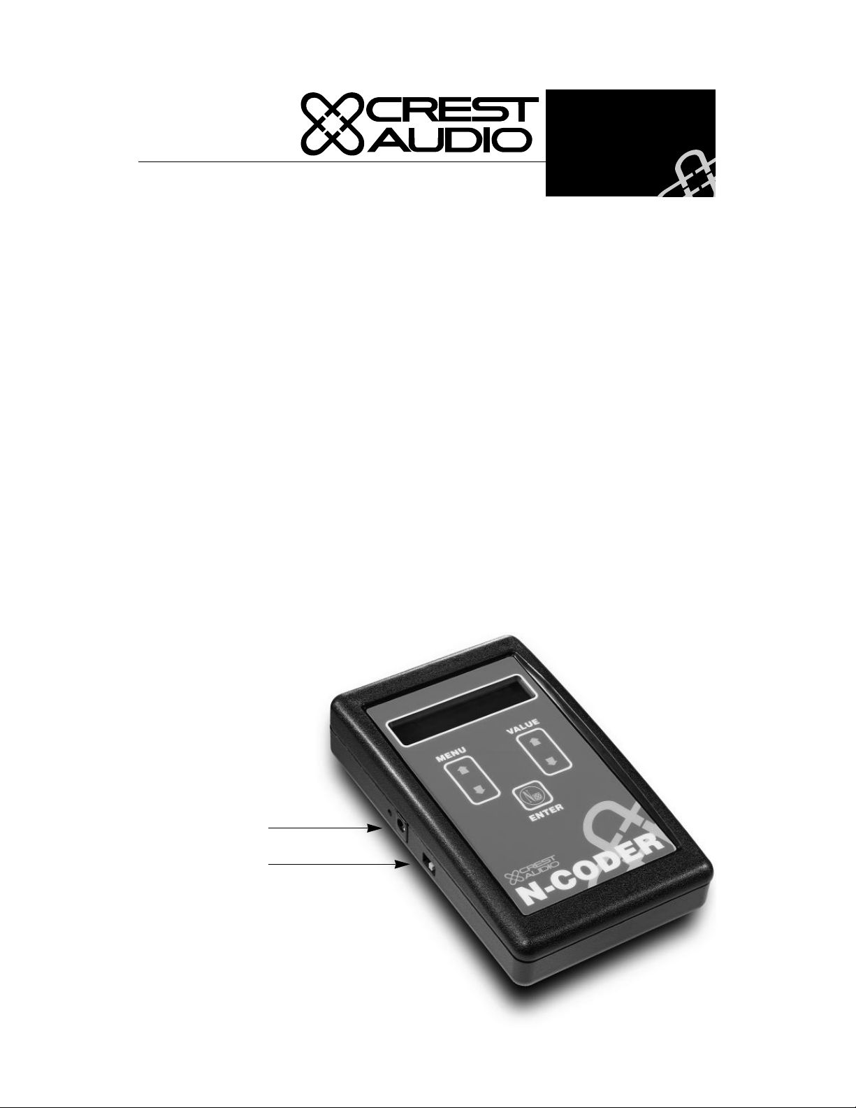
About the N-Coder
The hand-held N-Coder is used to configure all Input Processing “NC-” Modules except
for DSP modules. The N-Coder allows you to change parameters affecting the amplifer's
level, eq settings, crossover point, etc. Once set, the parameters are stored in non-volatile
memory so that the amp will always power up the same way -- without battery backup.
Processing parameters can also be created and stored ahead of time in the N-Coder without any modules attached, then downloaded to the modules later.
Powering the N-Coder
The N-Coder can be powered from a common 9VDC battery or the supplied 12VDC wall
adapter. To install a battery in the N-Coder, remove the battery cover on the back of the
N-Coder, connect the battery to the snap-on terminal, insert the battery into the cavity, and
replace the cover. To connect the 12VDC wall adapter, insert the adapter cable plug into
the N-Coder’s 12VDC In port, and plug the wall adapter into a 120V 60Hz AC mains outlet. Whether powered by battery or wall adapter, the N-Coder must then be switched on.
(See diagram below). Note:
Notes: The N-Coder does not have an Auto-of f featur e . As suc h you must r emember to turn
off the unit after use. The unit's Serial Number is also located inside the battery compartment. When a 9VDC battery has been installed in the N-Coder AND the wall adapter is
connected, the N-Coder
will use the wall adapter as
its primary power source.
The N-Coder must always
be self-powered – a connected Input Processing
Module does not supply
power to the N-Coder.
12VDC in port
On/Off switch
Page 2
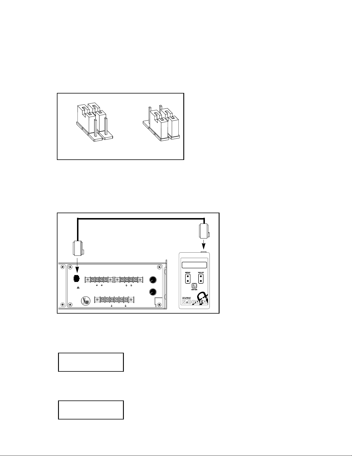
N-Coder Setup Jumpers.
All NC Modules have internal jumpers used to set the module for operation with NexSys
or N-Coder. These jumpers are labeled “W4 W5” on the Input module circuit board. The
“NC-NXS” jumper position allows operation with NexSys, while the “NCODE” jumper
position permits the Input module to be programmed through N-Coder (or N-Coder/PC
software) when the amplifier is off. Note: Modules shipped as separate items or with non-
N-Coder/NexSys Setup Jumpers Diagram.
NexSys-related orders are configured
for use with N-Coder; the jumper is set
in the "NCODE" position. Complete
NexSys systems are pretested at the factory; the jumper is set to the "NC-NXS"
N-CODE
NC-NXS
N-Coder Setup
N-CODE
NC-NXS
NexSys Setup
position. If N-Coder is being used,
jumper position must be in the
“NCODE” position.
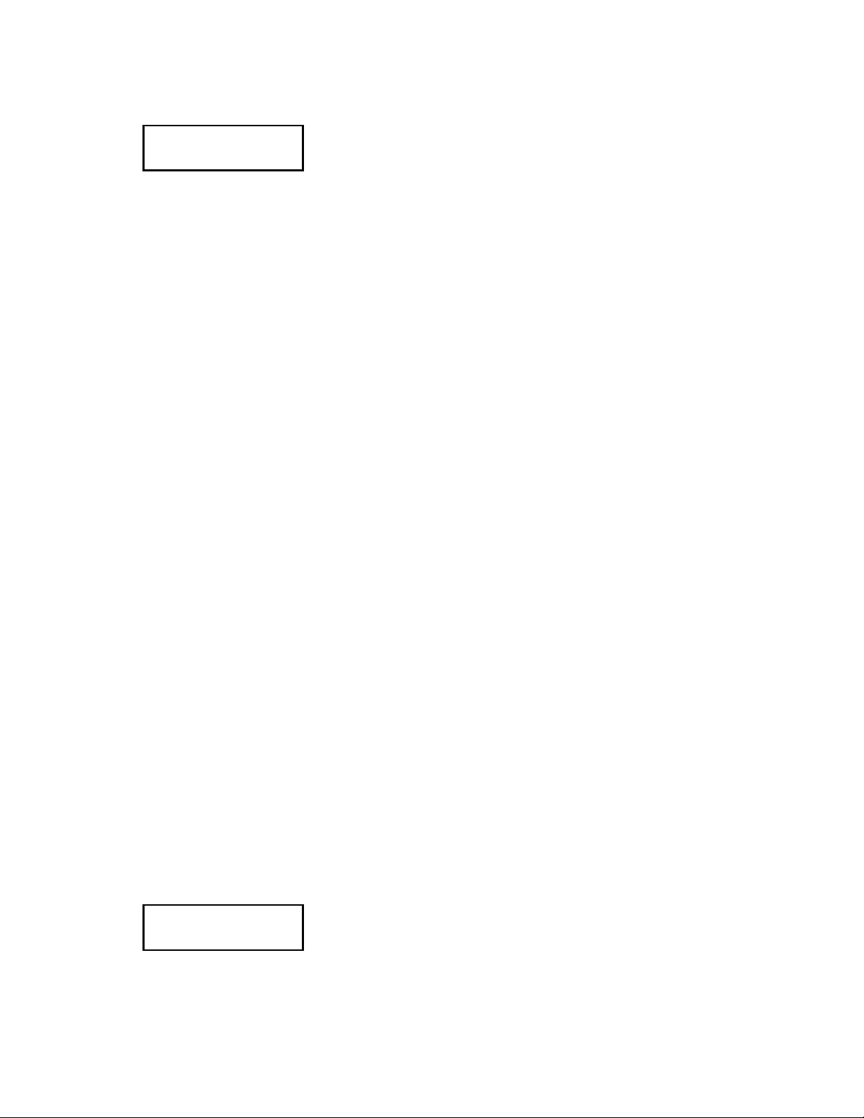
Connecting the N-Coder to the Input Processing Module
The N-Coder is connected to Input Processing Modules using an RJ-14 cord (supplied).
One end of the cord plugs into the N-Coder’s RJ-14 port (located on the top of the NCoder), and the other end plugs into the Input Processing Module’s Data Port. (See diagram below).
NOTE: the supplied RJ-14
cord (Crest part number
82510045) uses a ‘six conductor’cable. It is NOT the
same as a common telephone cord, which uses a
‘four-conductor’ cable.
Model
CC-BLK
N-Coder
Data
Port
READING DEVICE:
NC-SCO
Out A
HP
LP
Input A
–
+
Out B
HP
LP
Input B
–
+
Model
NC-SCO
5
Level
4
6
A
3
7
2
8
1
9
0
10
5
Level
4
6
B
3
7
2
8
1
9
0
10
Programming with N-Coder connected to module
Connect the N-Coder to the Input Processing Module using the supplied RJ-14 cable.
Once turned on, the N-Coder will display:
Crest Audio, Inc
Revision N.NN
N-Coder will automatically identify the connected module, read its current settings, and
briefly display the module ID (NC-IPN is used as an example here):
Reading Module:
NC-IPN
Page 3
Then N-Coder will then display current parameters for the module, beginning with:
CH A Level
* -80dB *
To scroll through the adjustable parameters, use the ‘Up’ [d] and ‘Down’ [f] MENU
keys. Parameter titles will be shown on the top line, with the parameter values displayed
on the second line. (Parameter values that are currently in effect are always bracketed by
asterisks). Parameter values can be changed by using the ‘Up’and ‘Down’VALUE keys.
Programming with N-Coder connected to module (continued)
Note: Changes to parameter values can be ‘auditioned’if you are passing signal
through the amplifier to your loudspeakers/drivers. However, these audible changes will
not be permanent unless you:
A: Save the settings directly to the module; or
B: Save the settings to the N-Coder for later download.
The following NC-IPN (Basic Input module) parameters are common to all NC Input
Processing modules:
Parameter Selectable Values
CH A Level 0dB to -80dB
CH B Level 0dB to -80dB
Phase A+ B+ / A- B- / A- B+ / A+ B-
WRITETOMODULE Yes / No
STORETOMEMORY Yes / No
READFROMMEMORY Yes / No
Channel A and B levels are attenuated in whole number dB steps.
Four different channel phase settings are available.
Once you have adjusted a parameter to the desired value, press ENTER. This will cause
the displayed parameter value to be saved into the N-Coder’s buffer. This will be indicated by the asterisks that appear to either side of the displayed (“current”) value.
Writing Settings to the Module
Parameter adjustments can be saved to the non-volatile module memory by scrolling to
the “Write To Module” menu command, selecting the value “Yes”, and pressing
ENTER:
WRITE TO MODULE
* Yes *
Remember that when you execute a “Write to Module” menu command, only those
parameter values that are bracketed by asterisks will be written to the module!
Page 4

Storing Settings Within the N-Coder
The “Store to Memory” menu command permits the storage of up to 32 module parameter settings within the N-Coder. Settings may be read from a module and then stored in
the N-Coder for ‘porting’ to other modules, or settings can be configured right in the NCoder for downloading to modules later. Settings are stored in the N-Coder even if the NCoder is turned off; only overwriting these settings will cause them to change.
Once parameter values hav e been selected and stored in the N-Coder's buffer (by pressing
ENTER with the desired parameter values displayed), this data can be stored in the NCoder by scrolling to the “Store to Memory” menu command:
STORETOMEMORY
* 1: ??? *
Notice the second line of the display . N-Coder permits the storage of up to 32 module presets; the display above indicates that preset #1 is empty and is ready to use for storage.
With the ‘Up’[d] and ‘Down’ [f] VALUE keys, you may scroll among the 32 presets.
Press ENTER to store the parameter values currently residing in the N-Coder's buffer as
Preset #1. The display will briefly show:
Storing to
Buffer 1
When a “Store to Memory” menu command is executed, only the parameter values currently in effect (bracketed by asterisks) will be written to the N-Coder’s memory!
N-Coder automatically assigns the module name to the Preset title. If you scroll to the
“Read from Memory” menu command, you can use the VALUE keys to view the various
stored presets in the N-Coder. Presets will display like this:
READFROMMEMORY
1: NC-IPN
Page 5

Recalling Stored N-Coder Settings
for Download to Input Processing Module
Stored settings residing in the N-Coder can be easily downloaded to Input Processing
Modules. Connect the N-Coder to the Input Processing Module using the supplied RJ-14
cable. Once turned on, the N-Coder will display:
Crest Audio, Inc
Revision N.NN
N-Coder will automatically identify the connected module, read its current settings, and
briefly display the module ID (NC-IPN is used as an example here):
Reading Module:
NC-IPN
Then N-Coder will display current parameters for the connected module, beginning with:
CH A Level
* -80dB *
Scroll through the adjustable parameters, using the ‘Up’[d] and ‘Down’ [f] MENU
keys until the following is displayed:
READ FROM MEMORY:
No
Using the ‘Up’ [d] and ‘Down’ [f] VALUE keys, you can scroll among the 32 stored
presets. Once you find the desired preset for the connected module, the display will look
like this:
READ FROM MEMORY:
1: NC-IPN
(Note that N-Coder will not permit module settings for one type of module to be downloaded to a different module type). Press ENTER to move the display presets from N-
Coder memory to the N-Coder's buffer. N-Coder will briefly display:
Recalling From
Buffer 1
Parameters recalled from the N-Coder’s memory will be displayed, beginning with:
CH A Level
* -80dB *
You may then change parameter values (if desired) and download the settings to the module by following the instructions for Writing Settings to the Module.
Page 6

Stand-Alone Programming with the N-Coder
Module settings can be programmed ahead of time without the N-Coder connected to a
module. Saved settings can then be downloaded to the module at a later time.
Turn on the unconnected N-Coder, which will display:
Crest Audio, Inc
Revision N.NN
N-Coder will then prompt for module selection:
Select Module:
NC-IPN
Note that once a module is selected, it cannot be unselected. To select a different module,
just cycle the N-Coder's power.
Scroll through the modules by using the ‘Up’and ‘Down’VALUE keys, and press ENTER
to select the desired module type. (NC-IPN is used as an example here). The N-Coder will
then display parameters, beginning with:
CH A Level
* -80dB *
To scroll through the adjustable parameters, use the ‘Up’ [d] and ‘Down’ [f] MENU
keys. Parameter titles will be shown on the top line, with the current parameter values
displayed on the second line. (Currently-selected parameter values are always bracketed
by asterisks). Parameter values can be changed by using the 'Up' and 'Down' VALUE
keys, pressing ENTER to select the desired parameter value.
Once parameter values have been selected and moved to the N-Coder’s buffer, follow
the instructions for Storing Settings Inside the N-Coder.
Note: Once stored, settings may be changed and stored into a different buffer. However,
to work with a different module type, power must be cycled.
Page 7

N-Coder SPECIFICATIONS
Display: 2 x 16 character LCD window
Connectors: RJ-14 jack connection to NC module (cable supplied)
Power Source: 12VDC external power input (supplied), or 9VDC battery
Controls: On/Off switch and panel buttons (MENU,VALUE, ENTER)
N-Coder RJ-14 Cable Pinout Information
Page 8

N-Coder - Menu Command Overview by Module
NC-IPN - Basic Input
NC-IPE - Input with Priority Page
CH A Level
CH B Level
Phase
WRITE TO MODULE
STORE TO MEMORY
READ FROM MEMORY
NC-MEQ - Mono EQ
CH A Level
CH B Level
Phase
EQ LF Boost
EQ LF Freq
EQ LF BW
EQ LM Boost
EQ LM Freq
EQ LM BW
EQ HM Boost
EQ HM Freq
EQ HM BW
EQ HF Boost
EQ HF Freq
EQ HF BW
HPF Freq
HPF Trim
LPF Freq
LPF Trim
WRITE TO MODULE
STORE TO MEMORY
READ FROM MEMORY
NC-SEQ - Stereo EQ
CH A Level
CH B Level
Phase
CH A EQ LF Boost
CH A EQ LF Freq
CH A EQ LF BW
CH A EQ LM Boost
CH A EQ LM Freq
CH A EQ LM BW
CH A EQ HM Boost
CH A EQ HM Freq
CH A EQ HM BW
CH A EQ HF Boost
CH A EQ HF Freq
CH A EQ HF BW
CH B EQ LF Boost
CH B EQ LF Freq
CH B EQ LF BW
CH B EQ LM Boost
CH B EQ LM Freq
CH B EQ LM BW
CH B EQ HM Boost
CH B EQ HM Freq
CH B EQ HM BW
CH B EQ HF Boost
CH B EQ HF Freq
CH B EQ HF BW
WRITE TO MODULE
STORE TO MEMORY
READ FROM MEMORY
Parameter Selectable
Values
CH A Level 0dB to -80dB
CH B Level 0dB to -80dB
Phase A+ B+
A- BA- B+
A+ B-
WRITETOMODULE Yes / No
STORETOMEMORY Yes / No
READFROMMEMORY Yes / No
EQ LF Boost -12 to +12dB
EQ LF Freq 20Hz to 2kHz
EQ LF BW 1/6 to 1-2/3 oct.
EQ LM Boost -12 to +12dB
EQ LM Freq 20Hz to 2kHz
EQ LM BW 1/6 to 1-2/3 oct.
EQ HM Boost -12 to +12dB
EQ HM Freq 210Hz to 20kHz
EQ HM BW 1/6 to 1-2/3 oct.
EQ HF Boost -12 to +12dB
EQ HF Freq 210Hz to 20kHz
EQ HF BW 1/6 to 1-2/3 oct.
HPF Freq 75Hz to 8kHz
HPF Trim 0db to -20db
LPF Freq 75Hz to 8kHz
LPF Trim 0db to -20db
NC-MCO - Mono Crossover
CH A Level
CH B Level
Phase
HPF Freq
HPF Trim
LPF Freq
LPF Trim
WRITE TO MODULE
STORE TO MEMORY
READ FROM MEMORY
v. 1.0 11/17/97
NC-SCO - Stereo Crossover
CH A Level
CH B Level
Phase
CH A HPF Freq
CH A HPF Trim
CH A LPF Freq
CH A LPF Trim
CH B HPF Freq
CH B HPF Trim
CH B LPF Freq
CH B LPF Trim
WRITE TO MODULE
STORE TO MEMORY
READ FROM MEMORY
A4400049
Crest Audio reserves the right to make improvements in manufacturing or design which may affect
specifications.
Crest Audio specification literature is available in
downloadable PDF file format; visit our website at
http://www.crestaudio.com. NexSys is a registered
trademark of Crest Audio Inc. ©1997 Crest Audio
Inc.
Crest Audio Inc.
100 Eisenhower Dr., Paramus NJ 07652 USA
TEL: 201.909.8700 FAX: 201.909.8744
http://www.crestaudio.com
Printed in USA
 Loading...