

Page 1
SAFETY FIRST
1. Installation of this TV Wall Mount will be easier with two people.
2. Some images in this guide may vary slightly from the actual
components supplied.
3. Ensure this instruction manual is completely read and
understood before attempting installation.
4. This TV Wall Mount MUST NOT be installed solely in
plasterboard, bre cement and similar surfaces.
5. This TV Wall Mount MUST be installed in sound supporting
structures such as those made of timber, steel or masonry
using appropriate fasteners.
6. The supporting structure must be capable of sustaining
the combined weight of the TV Wall Mount and the display
otherwise the structure must be reinforced.
7. The fasteners supplied in this hardware pack allow for xing
into timber and masonry only. If installing into a supporting
structure made of steel, appropriate fasteners must be used
and sourced from an appropriate supplier.
8. Use appropriate tools and safety equipment and ensure
adequate ventilation during installation.
9. If uncertain about any aspect of installation, contact
The Crest Company or an installation professional.
Please retain these instructions for future reference.
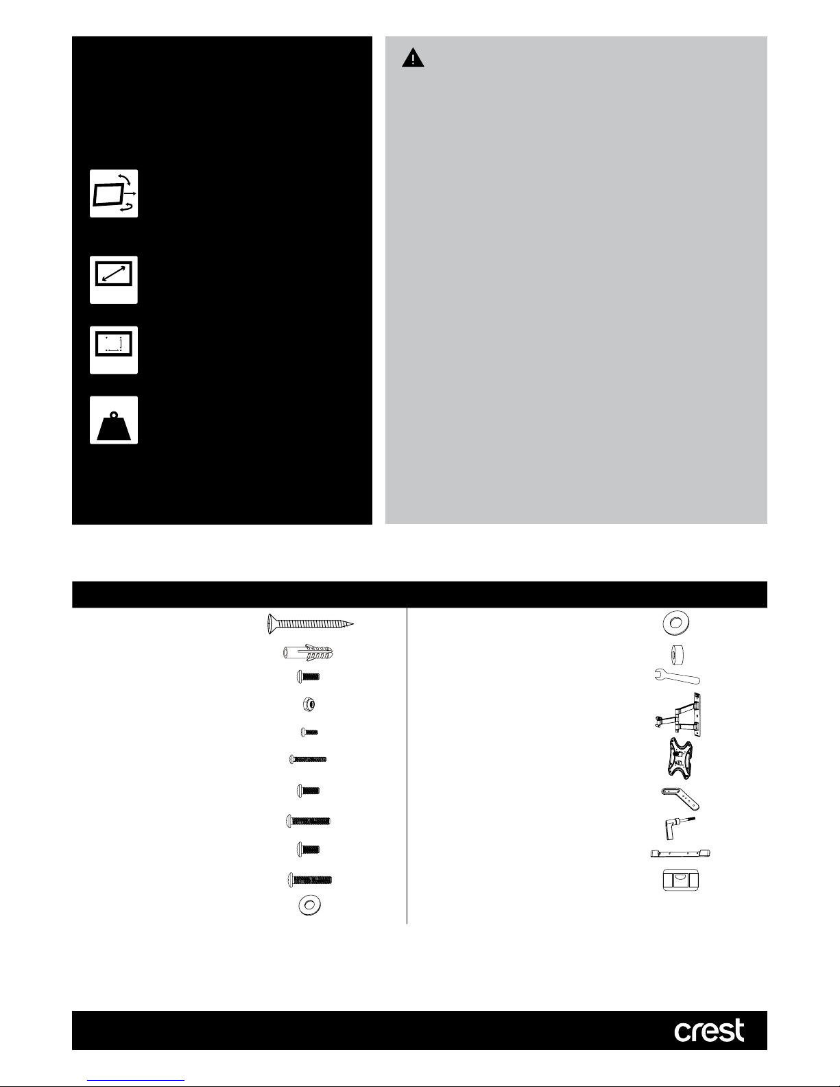
Hardware Kit Contents
ITEM DESCRIPTION QTY ITEM DESCRIPTION QTY
A Screw 3
L
M8 Washer
4
B Concrete Anchor 3
M
Spacer
8
C M6 x 12mm Bolt 8 N S10 Wrench 1
D M6 Locknut 8 O Wall Plate 1
E M4 x 12mm Bolt 4
F M4 x 20mm Bolt 4 P Display Plate 1
G M6 x 12mm Bolt 4 Q Display Plate Adaptors 4
H M6 x 30mm Bolt 4 R Tilt Adjustment Knob 1
I M8 x 12mm Bolt 4 S Plastic Cover 2
J M8 x 30mm Bolt 4 T Spirit Level (included) 1
K M6 Washer 4
MFP5FM
TV Wall Mount
Compatible TV Size
This TV Wall Mount ts 25-55”
(63-140cm) TV Screens
25-55”
Maximum TV Weight
This TV Wall Mount supports TVs
weighing up to 35kg
HOLDS
35
kg
Maximum Mounting Pattern
This TV Wall Mount has a mounting
hole pattern up to 400x400mm (WxH)
400x400mm
Full Motion
This TV Wall Mount allows you to move
your TV at all angles and extends out
up to 41cm from your wall
10.
Page 2

DRYWALL INSTALLATION (TIMBER SUPPORTS):
• Adjustable spanner/socket set
• Philips head screwdriver
• Power drill
• High speed 3mm drill bit
• Spirit level (included) and pencil
MASONRY INSTALLATION:
• Adjustable spanner/socket set
• Philips head screwdriver
• Power drill with hammer function
• 8mm Masonry drill bit
• Spirit level (included) and pencil
• Hammer
Tools Required
Using Spirit Level
Use the supplied spirit level to level your TV Wall mount before installation.
Step 1: Remove Front Part from Mount
Remove the front part of the mount from the back part by removing the wing nuts and washers shown (see Fig.1).
Place the wing nuts and washers in a safe location.
Step 2: Fix Wall Plate to Wall
A. INSTALLING IN DRYWALL (TIMBER SUPPORTS)
WARNING: If attaching this TV Wall Mount using this method, you MUST position the wall plate over a wall stud. The
Crest Company will not accept any damages that may occur and holds no responsibility for incorrectly installed TV
Wall Mounts.
1. Locate the centre of two adjacent timber studs. Crest recommends the use of a stud finder (not included).
(NOTE: You must use the centre of the stud to avoid cracking or splitting the timber during installation).
2. Mark 3 fixing holes over the stud centre using the wall plate as a guide. Ensure Wall Plate is straight and level.
3. Pre-drill holes to a depth of 75mm using a high speed 3mm drill bit. If installing in hardwood, larger diameter and deeper
holes may be required.
4. Attach the Wall Plate using the screws (A) (see Figure 2). Do not over tighten.
B. INSTALLING IN MASONRY
WARNING: Ensure you have a minimum of 35mm of actual concrete/brick thickness in the hole for the anchors.
Do not drill into mortar joints. Installer must verify that the supporting surface will safely support the combined
weight of the mount and TV.
1. Mark 3 fixing holes using the Wall Plate as a guide. Ensure Wall Plate is straight and level.
2. Pre-drill holes to a minimum depth of 75mm using 8mm masonry drill bit. Clean out holes.
3. Fully insert the concrete anchors (B). Tap in with hammer if required.
4. Attach the Wall Plate using the screws (A) (see Figure 3). Do not over tighten.
Figure 1
Page 3

Step 3: Attach Display Plate
1. Using a second person for assistance, lay your TV face down on something soft so as not to scratch the TV screen.
2. Check the back of your TV to find the appropriate mounting pattern. If the mounting pattern is spaced more than 200mm x
200mm apart, you will need to attach the Display Plate Adaptors (Q) to the Display Plate (P). Use the M6 x 12mm (C) bolts,
M6 lock nuts (D) and S10 wrench (N) for this (see Figure 4).
3. Sort through the provided bolts until you find the correct size that easily fits into the back of your TV and fits snugly (the
bolt must turn at least 3 full turns. If you feel resistance stop immediately and select a smaller bolt.
The Crest Company is not responsible for any damage caused by screwing the bolt too far into the back of the TV.
Once you have selected the correct bolts (E to J), find the corresponding washers (K to L). If no bolts fit you will need to go
to your local hardware supplier to find the correct bolt and washer sizes.
4. Gently put the Display Plate on the back of the TV and align to the correct holes. Make sure it is oriented as shown (see
Fig. 5).
5. Using the correct bolt size and length, insert these through corresponding washers to attach the Display Plate to the rear
of the TV (see Figure 6). If one of the smaller bolts is selected then use the hole spacer (M) to fill out the Display Plate hole
and reduce its size for a snugger fit To avoid damaging TV, do not over tighten bolts.
Figure 3
A
B
A
A
A
A
A
Figure 2
Figure 4
Figure 5
Top
Bottom
Figure 6
Without spacers
With spacers
Page 4

5 YEAR WARRANTY
Olbertz Holdings Pty Ltd ACN 010 003 933 trading as The Crest Company of 165 South Pine Road, Brendale, Queensland, 4500, Ph: 1800 812 261,
www.crest.com.au, warrants that if this Crest product purchased by you from The Crest Company or a retail outlet is found by The Crest Company to be
defective in workmanship or materials within 5 years of the date of purchase, The Crest Company will (at its election) either repair that product, replace the
product, supply an equivalent product or pay the costs of repairing or replacing the product or acquiring an equivalent product.
This limited warranty will not extend to or cover any expenses associated with removing, demounting the original product or installing the repaired, replaced
or equivalent product or all or any of its components, you must bear these expenses. It also does not cover damage or loss resulting from intentional or
unintentional misuse of, tampering with, alterations to or incorrect installation of this product or use of this product for purposes other than that for which it
is designed or in a manner inconsistent with the product’s instructions. This limited warranty also does not apply to damage or loss resulting from fair wear
and tear or events beyond The Crest Company control including but not limited to natural disasters.
In order to claim under this warranty, you must contact The Crest Company and return to The Crest Company (via our nominated reply paid address) the
product and its components and proof of purchase (including the date and location of purchase) so that The Crest Company can verify the defect and
your purchase.
Our goods come with guarantees that cannot be excluded under the Australian Consumer Law. You are entitled to a replacement or refund for a major
failure and compensation for any other reasonably foreseeable loss or damage. You are also entitled to have the goods repaired or replaced if the goods
fail to be of acceptable quality and the failure does not amount to a major failure. The benets given by this warranty are in addition to other rights and
remedies which you may have under a law in relation to the goods or services to which the warranty relates.
1645/5
PO Box 5658 Brendale
QLD Australia 4500
Customer Support
1800 812 261
www.crest.com.au
AUSTRALIAN OWNED
Proudly brought to you by:
Step 5: Full Motion Adjustment & Maintenance
1. To change the tilt angle of your display, have one person hold the display firmly in place while another person loosens
the tilt adjustment knob. Once loosened, move your display to the desired position, and then re-tighten the knob (see
Figure.8). Do not release the display until the knob is fully tightened.
NOTE: The tilt adjustment knob has a ratcheting feature.
If you need to change the position of the knob without tightening or loosening it, simply pull the knob outward before
turning.
2. Swivel adjustments can be made by moving the display to the desired position. Be careful that fingers or cables do not
get pinched when moving the mount. Level correction adjustments can be made by rotating the display in the needed
direction. If it is too difficult to turn the display or if the display does not stay in position, adjust the tension of the wing nuts
located behind the front part of the mount (see Fig. 9). Adjust both wing nuts evenly.
Step 4: Final Assembly
1. With the help of another person, place the Display Plate with your TV attached into the Wall Plate.
Carefully lift and hook the front part of the mount onto the back part of the mount. Do not release the display until the
mount is securely connected.
Replace the wing nuts and washers removed in part 1 and tighten.
IMPORTANT! The wing nuts must remain sufficiently tightened at all times to prevent the display from being accidentally
knocked from the mount.
2. Attached the Plastic Covers (S) by pressing them onto the wall plate (see Figure 7).
3. Cables can be routed through the hooks located on the Wall Plate.
WARNING: Do not loosen too much as the Wall Mount may fall apart.
Check your TV Wall Mount is secure and safe to use at regular intervals (at least every three months).
Figure 7
Figure 8 Figure 9
 Loading...