

Page 1
FB-I-O Rev M
Installation & Operation Manual
Models: 1.5 - 5.0
WARNING
Save this manual for future reference.
This manual must only be used by
a qualified heating installer / service
technician. Read all instructions,
including this manual and the Crest
Service Manual, before installing.
Perform steps in the order given.
Failure to comply could result in
severe personal injury, death, or
substantial property damage.
Page 2

Contents
HAZARD DEFINITIONS .................................................... 2
PLEASE READ BEFORE PROCEEDING ........................ 3
THE CREST -- HOW IT WORKS ................................... 4-5
RATINGS ........................................................................... 6
1. DETERMINE BOILER LOCATION
Clearances ......................................................................... 7
Provide Air Openings to Room .......................................... 8
Flooring and Foundation ................................................... 8
Vent and Air Piping ............................................................ 8
Prevent Combustion Air Contamination ............................. 8
Using an Existing Vent System to Install a New Boiler ..... 9
Corrosive Contaminants and Sources ............................... 9
Removing a Boiler from Existing Common Vent .............. 10
Remove Boiler from Wood Pallet ..................................... 11
Combustion and Ventilation Air Requirements ........... 12-13
2. GENERAL VENTING
Direct Venting Options - Sidewall Vent ............................ 14
Direct Venting Options - Vertical Vent .............................. 14
Direct Venting Options - Vert. Vent, Opt. Rm Air ............. 14
Direct Venting Options - Vert. Vent, Sidewall Air ............. 14
Install Vent and Combustion Air Piping ........................... 15
Air Inlet Pipe Materials ................................................ 15
Requirements for Installation in Canada .......................... 15
Vent and Air Piping .......................................................... 16
Air Intake / Vent Connections .......................................... 16
Min./Max. Combustion Air & Vent Piping Lengths ........... 17
Vent and Air Piping .......................................................... 17
Common Venting ............................................................. 18
3. VERTICAL DIRECT VENTING
Vent/Air Termination - Vertical ......................................... 19
Determine Location ..................................................... 19
Prepare Roof Penetrations ......................................... 19
Termination and Fittings ........................................ 19-20
Multiple Vent/Air Terminations .................................... 20
4. SIDEWALL DIRECT VENTING
Vent/Air Termination - Sidewall ................................... 21-23
Determine Location ................................................ 21-23
Prepare Wall Penetrations .......................................... 22
Termination and Fittings ............................................. 22
Multiple Vent/Air Terminations ............................... 22-23
Room Air ..................................................................... 23
5. HYDRONIC PIPING
System Water Piping Methods ......................................... 24
Low Water Cutoff Device ................................................. 24
Chilled Water System ....................................................... 24
Freeze Protection ............................................................. 24
General Piping Information .............................................. 24
Circulator Sizing ............................................................... 25
Near Boiler Piping Components .................................. 26-30
6. GAS CONNECTIONS
Connecting Gas Supply Piping ........................................ 31
Natural Gas ...................................................................... 32
Pipe Sizing for Natural Gas ........................................ 32
Natural Gas Supply Pressure Requirements ............. 32
Propane Gas .................................................................... 32
Pipe Sizing for Propane Gas ...................................... 32
Propane Supply Pressure Requirements ................... 32
Check Inlet Gas Supply .............................................. 33-34
Gas Pressure ................................................................... 34
Gas Valve Replacement .................................................. 34
7. FIELD WIRING
Line Voltage Connections ................................................ 35
Low Voltage Connections ................................................ 36
Wiring of the Cascade ...................................................... 37
8. CONDENSATE DISPOSAL
Condensate Drain ............................................................ 39
9. STARTUP ............................................................... 40-45
10. OPERATING INFORMATION
General ........................................................................ 46-48
Cascade ........................................................................... 49
Sequence of Operation .................................................... 50
Status Screen ................................................................... 51
Main Screen ..................................................................... 52
11. MAINTENANCE
Maintenance & Annual Startup .............................. 53-57
12. DIAGRAMS
Ladder Diagrams .............................................. 58,60,62
Wiring Diagrams ............................................... 59,61,63
Revision Notes .................................................. Back Cover
Hazard definitions
The following defined terms are used throughout this manual to bring attention to the presence of hazards of various risk levels or
to important information concerning the life of the product.
DANGER
WARNING
CAUTION
CAUTION
NOTICE
2
DANGER indicates an imminently hazardous situation which, if not avoided, will result in death or serious
injury.
WARNING indicates a potentially hazardous situation which, if not avoided, could result in death or serious
injury.
CAUTION indicates a potentially hazardous situation which, if not avoided, may result in minor or moderate
injury.
CAUTION used without the safety alert symbol indicates a potentially hazardous situation which, if not
avoided, may result in property damage.
NOTICE indicates special instructions on installation, operation, or maintenance that are important but not
related to personal injury or property damage.
Page 3

Please read before proceeding
Installation & Operation Manual
WARNING
NOTICE
Installer – Read all instructions, including
this manual and the Crest Service Manual,
before installing. Perform steps in the
order given.
User – This manual is for use only
by a qualified heating installer/
service technician. Refer to the User’s
Information Manual for your reference.
Have this boiler serviced/inspected by
a qualified service technician, at least
annually.
Failure to comply with the above could
result in severe personal injury, death or
substantial property damage.
When calling or writing about the boiler
– Please have the boiler model and serial
number from the boiler rating plate.
Consider piping and installation when
determining boiler location.
Any claims for damage or shortage in
shipment must be filed immediately
against the transportation company by
the consignee.
WARNING
DO NOT install units in rooms or
environments that contain corrosive
contaminants (see Table 1A on page 9).
Failure to comply could result in severe
personal injury, death, or substantial
property damage.
When servicing boiler –
• To avoid electric shock, disconnect electrical supply
before performing maintenance.
• To avoid severe burns, allow boiler to cool before
performing maintenance.
Boiler operation –
• Do not block flow of combustion or ventilation air to
the boiler.
• Should overheating occur or gas supply fail to shut off,
do not turn off or disconnect electrical supply to
circulator. Instead, shut off the gas supply at a location
external to the appliance.
• Do not use this boiler if any part has been under water.
The possible damage to a flooded appliance can be
extensive and present numerous safety hazards. Any
appliance that has been under water must be replaced.
WARNING
WARNING
Factory warranty (shipped with unit) does
not apply to units improperly installed or
improperly operated.
Failure to adhere to the guidelines on this
page can result in severe personal injury,
death, or substantial property damage.
If the information in this manual is not
followed exactly, a fire or explosion may
result causing property damage, personal
injury or loss of life.
This appliance MUST NOT be installed in
any location where gasoline or flammable
vapors are likely to be present.
WHAT TO DO IF YOU SMELL GAS
• Do not try to light any appliance.
• Do not touch any electric switch; do
not use any phone in your building.
• Immediately call your gas supplier
from a near by phone. Follow the
gas supplier’s instructions.
• If you cannot reach your gas supplier,
call the fire department.
• Installation and service must be
performed by a qualified installer,
service agency, or the gas supplier.
Boiler water –
• Thoroughly flush the system (without boiler
connected) to remove sediment. The high-efficiency
heat exchanger can be damaged by build-up or
corrosion due to sediment.
• Do not use petroleum-based cleaning or sealing
compounds in the boiler system. Gaskets and seals in
the system may be damaged. This can result in
substantial property damage.
• Do not use “homemade cures” or “boiler patent
medicines”. Serious damage to the boiler, personnel,
and/or property may result.
• Continual fresh make-up water will reduce boiler life.
Mineral buildup in the heat exchanger reduces heat
transfer, overheats the stainless steel heat exchanger,
and causes failure. Addition of oxygen carried in by
makeup water can cause internal corrosion in system
components. Leaks in boiler or piping must be repaired
at once to prevent the need for makeup water.
Freeze protection fluids –
• NEVER use automotive antifreeze. Use only inhibited
propylene glycol solutions, which are specifically
formulated for hydronic systems. Ethylene glycol is
toxic and can attack gaskets and seals used in hydronic
systems.
3
Page 4

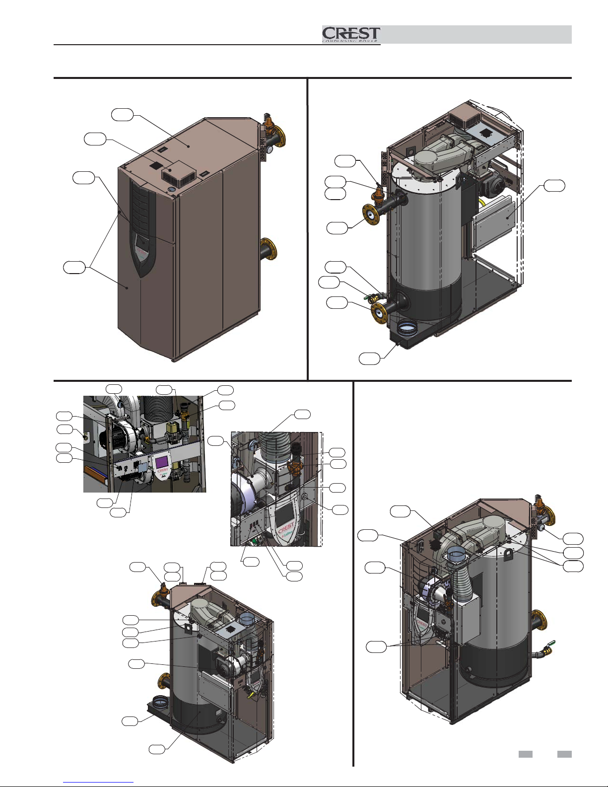
The Crest - How it works...
1. Front access panels
Provides access to the controls compartment.
2. Top access panel
Provides access to the burner compartment.
3. Air pressure switch
The air pressure switch detects blocked flue/vent conditions.
4. Blowers
The blowers pull in air and gas through the venturis (item
34). Air and gas mix inside the blowers and are pushed into the
burner, where they burn inside the combustion chamber.
5. Boiler drain connection
Location from which the heat exchanger can be drained.
6. Boiler inlet temperature sensor
The boiler inlet temperature sensor monitors system return
water temperature. If selected as the controlling sensor,
the control module will adjust the boiler firing rate so the inlet
temperature matches the set point.
7. Boiler outlet temperature sensor
The boiler outlet temperature sensor monitors boiler outlet
water temperature. If selected as the controlling sensor,
the control module will adjust the boiler firing rate so the outlet
temperature matches the set point.
8. Burner (not shown)
Integral dual chamber design with a stress free metal fiber
outer mesh and durable stainless steel structure. Provides two
(2) independent firing rates up to 25:1 turndown.
9. Condensate drain connection
The condensate drain connection provides a connection
point to install a condensate drain line using flexible hose
provided.
10. Control module (on control panel assembly)
The control module responds to internal and external signals
and controls the blowers, gas valves, and pump(s), depending on
the application, to meet the heating demand.
11. Electronic display
Digital controls with SMART TOUCH screen technology, full
color display, and an 8" user interface screen.
12. Flame inspection windows
Two large high temperature quartz observation windows
provide views of each independent burner surface during
firing.
13. Dual flame sensors
The dual flame sensors are used by the control module to detect
the presence of a burner flame at both independent burner
surfaces.
14. Flue temperature sensor
The flue sensor monitors flue gas temperature. The control
module will modulate or shut the boiler down if the flue gas
temperature gets too high.
15. Gas connection pipe
The gas connection pipe is a threaded black iron pipe
connection (see Gas Connections Section for specific model
pipe size requirements). This pipe should be connected to the
incoming gas supply to deliver gas to the boiler.
16. Gas shutoff valve (inside unit)
The manual gas shutoff valve is used to isolate the boiler gas
train from the gas supply.
17. Gas valves
The gas valves sense the negative pressure created by the
blowers, allowing gas to flow only if the gas valves are powered
and combustion air is flowing.
18. Blower proving switches
Prove adequate airflow during prepurge.
Installation & Operation Manual
19. High limit devices (primary and backup)
The high limit devices are used to monitor the outlet water
temperature - if either device senses the water temperature
exceeding the predetermined setting, the boiler will shut down.
20. Ignition electrode
An electrical spark across the electrodes will ignite the first
burner.
21. Line voltage junction box
The line voltage junction box contains the connection points for
the line voltage power to the boiler (and pumps if used).
22. Line voltage wiring connections (knockouts)
Conduit connection points for the high voltage junction box.
23. Low gas pressure switch
Monitors gas supply pressure to the boiler and shuts the boiler
down in the event a low gas pressure condition occurs.
24. High gas pressure switch (not shown)
Monitors gas supply pressure to the burner and shuts the boiler
down in the event a high gas pressure condition occurs.
25. Low voltage connection board(s)
Connection boards used to connect external low voltage devices.
26. Low voltage wiring connections (knockouts)
Conduit connection points for the low voltage connection boards.
27. Low water cutoff probe (LWCO)
Ensures adequate water is supplied to the boiler. In the event of
inadequate water levels, the boiler will shut down.
28. Power switch
The On/Off power switch provides the ability to turn line voltage
power to the boiler on and off.
29. Relief valve
The safety relief valve protects the heat exchanger from an over
pressure condition. The boiler comes with a 50 PSI relief valve as
standard equipment. Optional settings are available.
30. Reset switch
Reset switch for the low water cutoff. Hold the switch for 10
seconds to reset.
31. Test switch
The test switch permits manual triggering of the LWCO
safety circuit to test the contacts and evaluate the integrity of the
circuit. Hold the switch for 10 seconds to test.
32. Firetube heat exchanger
High grade stainless steel WAVETM firetube design that extracts
heat from flue gases and transfers it directly into boiler water.
33. Temperature and pressure gauge
Monitors the outlet temperature of the boiler as well as the system
water pressure.
34. Venturis
Separate venturis control air and gas flow into two (2) independent
burner sections.
35. Water inlet
A 4" ANSI flange connects the return water from the system to the
heat exchanger.
36. Water outlet
A 4" ANSI flange connects the hot water supply from the boiler to
the system.
37. Ignition transformer
The transformer provides voltage to the ignition electrode (item
20).
38. Air arm temperature sensors (not shown)
Monitors fuel-air delivery temperature to the burner.
39. Air inlet cover (shipped loose)
Used with room air for combustion and to prevent debris from
entering the boiler.
40. Fuses
A low resistance resistor that acts as a sacrificial device to provide
overcurrent protection, of either the load or source circuit.
4
Page 5
The Crest - How it works... (continued)
Models 1.5 - 5.0
2
39
11
19
7
36
Installation & Operation Manual
29
10
1
Front View
34
19
30
31
MODELS 4.0 - 5.0
28
18
40
29
23
21
22
IMG00318
34
25
26
15
16
28
5
Rear View
18
MODELS 1.5 - 3.5
30
31
6
35
15
16
23
19
9
37
3
33
12
34
13
20
12
27
4
14
32
Left Side (inside unit)
17
Right Side (inside unit)
5
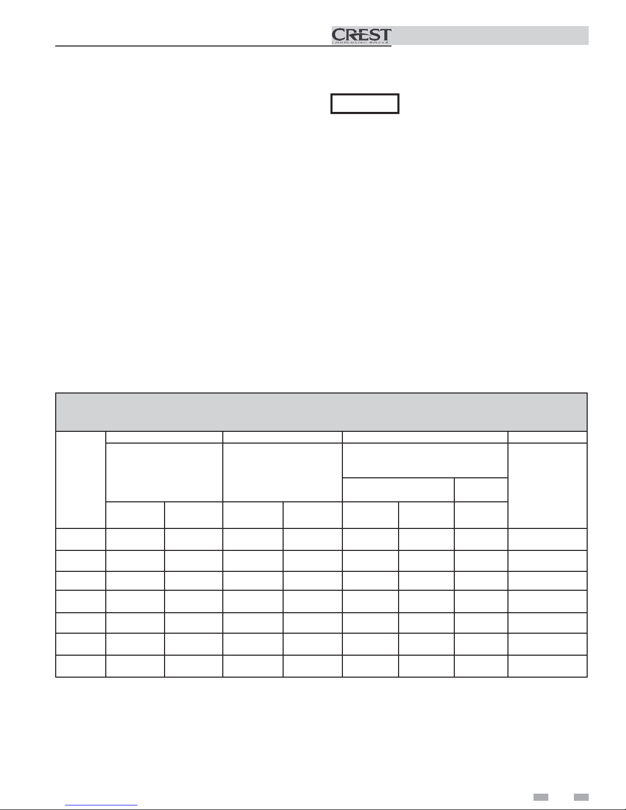
Page 6
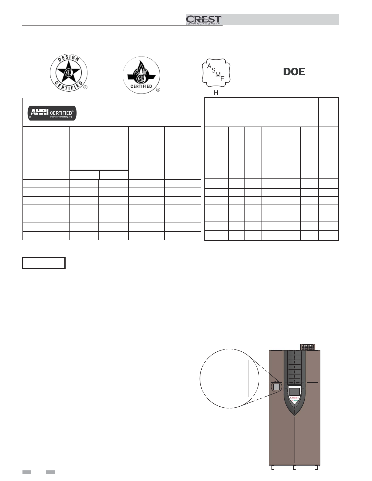
Ratings
Installation & Operation Manual
Crest
AHRI Rating
Model Number
Note: Change “N” to
“L” for L.P. gas models.
Min Max
FB(N,L)1500 60 1500 1380 1200
FB(N,L)2000 80 2000 1840 1600
FB(N,L)2500 125 2500 2300 2000
FB(N,L)3000 150 3000 2760 2400
FB(N,L)3500 200* 3500 3220 2800
FB(N,L)4000 335 4000 3720 4043
FB(N,L)5000 500 5000 4650 3235
Input
MBH
(Notes 4 - 8)
*For LP models the minimum input is 420 MBH.
NOTICE
Maximum allowed working pressure is located on the rating plate.
Notes:
1. The ratings are based on standard test procedures
prescribed by the United States Department of Energy.
2. Net AHRI ratings are based on net installed radiation of
sufficient quantity for the requirements of the building
and nothing need be added for normal piping and pickup.
Ratings are based on a piping and pickup allowance of
1.15.
3. Crest boilers require special gas venting. Use only
the vent materials and methods specified in the Crest
Installation and Operation Manual.
4. Standard Crest boilers are equipped to operate from sea
level to 4,500 feet only with no adjustments.
5. High altitude Crest Models 1.5, 2.0, 2.5, 3.0 and 3.5
boilers are equipped to operate from 3,000 to 12,000
feet and high altitude Crest Models 4.0 and 5.0 boilers
are equipped to operate from 3,000 to 5,500 feet. High
altitude models are manufactured with different control
parameters for high altitude operation, but the sequence
of operation given in this manual remains the same as
the standard boilers. A high altitude label (as shown in
FIG A.) is also affi xed to the unit.
6. Standard Crest boilers will de-rate by 2.2% for each 1,000
feet above sea level up to 4,500 feet when combustion
calibration is performed and CO2’s are adjusted to the
recommended levels.
Gross
Output
MBH
(Note 1)
Other Specifications
Net
AHRI
Ratings
Water,
MBH
(Note 2)
Appliance
Water
Content
Gallons
132 4" 4" 1 1/2" 8" 8" 3055
161 4" 4" 2" 8" 9" 3650
181 4" 4" 2" 10" 10" 4125
215 4" 4" 2" 10" 10" 4750
291 4" 4" 2 1/2" 12" 12" 6500
380 4" 4" 2 1/2" 14" 14" 8000
Pipe
Pipe
Size
Inlet
Gas Inlet
Size
Size
Outlet
96 4" 4" 1 1/2" 7" 7" 2500
7. High altitude Crest Models 1.5, 2.0, 2.5, 3.0 and 3.5 will
de-rate by 1.4% for each 1,000 feet above sea level up to 5,500
feet and 1.8% for each 1,000 feet above 5,500 feet.
8. High altitude Crest Models 4.0 and 5.0 will not de-rate up to
5,500 feet.
9. For Crest Models 4.0 and 5.0, installations above 5,500 feet
contact the factory.
10. Ratings have been confi rmed by the Hydronics Section of
AHRI.
UNIT EQUIPPED FOR
HIGH ALTITUDE
3,000 FT. TO 12,000 FT.
Air
Size
Vent
Size
(Note 3)
Weight
w/Water
(lbs.)
6
Figure A High Altitude Label Location
Page 7
1 Determine boiler location
Installation must comply with:
• Local, state, provincial, and national codes, laws,
regulations, and ordinances.
• National Fuel Gas Code, NFPA 54 / ANSI Z223.1 –
latest edition.
• Standard for Controls and Safety Devices for
Automatically Fired Boilers, ANSI/ASME CSD-1 latest edition, when required.
• National Electrical Code, NFPA 70 - latest edition.
• For Canada only: CSA B149.1 Installation Code,
CSA C22.1 Canadian Electrical Code Part 1 and any
local codes.
NOTICE
Before locating the boiler, check:
1. Check for nearby connection to:
• System water piping
• Venting connections
• Gas supply piping
• Electrical power
2. Locate the appliance so that if water connections
should leak, water damage will not occur. When
such locations cannot be avoided, it is
recommended that a suitable drain pan, adequately
drained, be installed under the appliance. The
pan must not restrict combustion air flow. Under no
circumstances is the manufacturer to be held
responsible for water damage in connection with
this appliance, or any of its components.
3. Check area around the boiler. Remove any
combustible materials, gasoline and other
flammable liquids.
WARNING
4. The Crest must be installed so that gas control
system components are protected from dripping or
spraying water or rain during operation or service.
5. If a new boiler will replace an existing boiler, check
for and correct system problems, such as:
• System leaks causing oxygen corrosion or heat
exchanger cracks from hard water deposits.
• Incorrectly-sized expansion tank.
• Lack of freeze protection in boiler water causing
system and boiler to freeze and leak.
6. The appliance must be installed on a level floor,
both front to back and side to side, for proper
condensate drainage.
7. If the optional neutralizing kit is to be used, elevate
the boiler at least 3" above the floor.
The Crest gas manifold and
controls met safe lighting and other
performance criteria when the boiler
underwent tests specified in ANSI
Z21.13/CSA 4.9 – latest edition.
Failure to keep boiler area clear
and free of combustible materials,
gasoline, and other flammable
liquids and vapors can result in
severe personal injury, death, or
substantial property damage.
Installation & Operation Manual
WARNING
WARNING
Provide clearances:
Clearances from combustible materials
- Hot water pipes ........................................................ 1/4"
- Sides .......................................................................... 0"
- Rear ........................................................................... 0"
- Front ......................................................................... 0"
- Top ........................................................................... 0"
- Floor ....................................................... Combustible
- Vent pipe - Follow special vent system manufacturer’s instructions
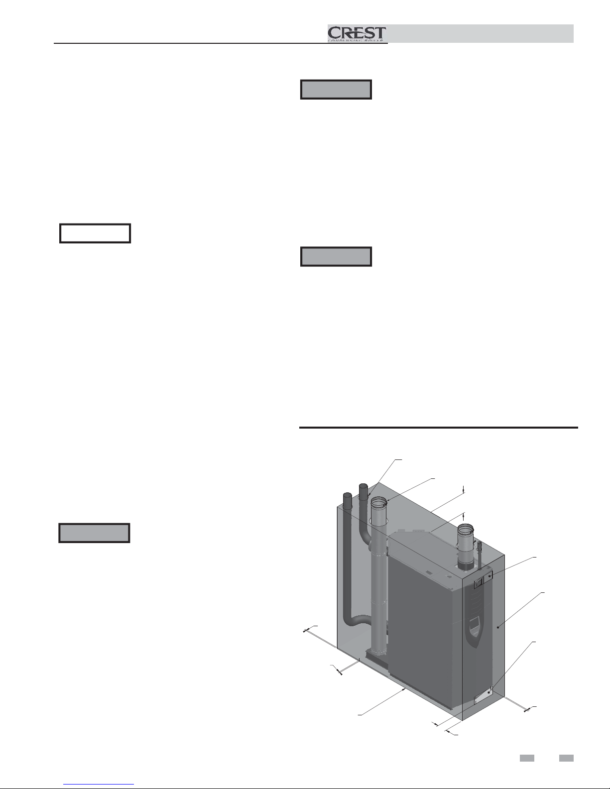
Figure 1-1 Clearances
0"
LEFT
0"
REAR
FLOOR: COMBUSTIBLE
This appliance is certified as an indoor appliance.
Do not install the appliance outdoors or locate
where the appliance will be exposed to freezing
temperatures or to temperatures that exceed 100°F
(37.8°C).
Do not install the appliance where the relative
humidity may exceed 93%. Do not install the
appliance where condensation may form on
the inside or outside of the appliance, or where
condensation may fall onto the appliance.
Failure to install the appliance indoors could result
in severe personal injury, death, or substantial
property damage.
This appliance requires a special venting system.
Use only the vent materials specified in this
manual. Failure to follow all instructions can
result in flue gas spillage and carbon monoxide
emissions, causing severe personal injury or death.
1" (25 MM) MINIMUM CLEAR ANCE
AROUND HOT WATER PIPES
VENT PIPE: FOLLOW SPECIAL VENT SYSTEM
MANUFACTURER'S INSTRUCTIONS
0"
TOP
VENTILATING*
AIR OPENING
CLOSED DOOR
VENTILATING*
AIR OPENING
0"
RIGHT
0"
FRONT
IMG00841
7
Page 8
1 Determine boiler location
Installation & Operation Manual
NOTICE
Recommended clearances for service access
- Sides .......................................................................... 24"
- Rear ........................................................................... 24"
- Front ......................................................................... 30"
- Top ........................................................................... 24"
Maintain minimum specified clearances for adequate
operation. All installations must allow sufficient space for
servicing the vent connections, water pipe connections, piping
and other auxiliary equipment, as well as the appliance. The
clearance labels on each appliance note the same service and
combustible clearance requirements as shown in this manual.
Multiple boilers may be installed side by side with no clearance
between adjacent boilers because this boiler is approved for
zero clearance from combustible surfaces; however, service
access will be limited from the sides.
Consult the Venting section of this manual for specific
installation instructions for the appropriate type of venting
system that you will be using.
If you do not provide the recommended
service clearances shown, it may not be
possible to service the boiler without
removing it from the space.
Provide air openings to room:
The Crest alone in boiler room
1. No air ventilation openings into the boiler room are
needed when clearances around the Crest are at least
equal to the SERVICE clearances shown in FIG. 1-1.
For spaces that do NOT supply this clearance, provide
two openings as shown in FIG. 1-1. Each opening must
provide one square inch free area per 1,000 Btu/hr of
boiler input.
2. Combustion air openings are required when using the
Room Air Option on page 23 of this manual.
The Crest in same space with other gas or oil-fired
appliances
1. Follow the National Fuel Gas Code (U.S.) or CSA B149.1
(Canada) to size/verify size of the combustion/ventilation
air openings into the space.
WARNING
2. Size openings only on the basis of the other appliances in
the space. No additional air opening free area is needed
for the Crest when it takes its combustion air from
outside (direct vent installation).
The space must be provided with
combustion/ventilation air openings
correctly sized for all other appliances
located in the same space as the Crest.
Failure to comply with the above warnings
could result in severe personal injury,
death, or substantial property damage.
8
Flooring and foundation
Flooring
The Crest is approved for installation on combustible flooring,
but must never be installed on carpeting.
WARNING
If flooding is possible, elevate the boiler sufficiently to prevent
water from reaching the boiler.
WARNING
Do not install the boiler on carpeting even if
foundation is used. Fire can result, causing
severe personal injury, death, or substantial
property damage.
Assure that the floor and structure is
sufficient to support the installed weight
of the boiler, including the water content
in the heat exchanger. If not, structural
building failure will result, causing severe
personal injury, death, or substantial
property damage.
Vent and air piping
The Crest requires a special gas vent system, designed for
pressurized venting.
The boiler is to be used for either direct vent installation or
for installation using indoor combustion air. When room air
is considered, see page 23 of this manual. Note prevention of
combustion air contamination below when considering vent/
air termination.
Vent and air must terminate near one another and may be
vented vertically through the roof or out a side wall, unless
otherwise specified. You may use any of the vent/air piping
methods covered in this manual. Do not attempt to install
the Crest using any other means.
Be sure to locate the boiler such that the vent and air piping
can be routed through the building and properly terminated.
The vent/air piping lengths, routing and termination method
must all comply with the methods and limits given in this
manual.
Prevent combustion air contamination
Install air inlet piping for the Crest as described in this
manual. Do not terminate vent/air in locations that can
allow contamination of combustion air. Refer to Table 1A,
page 9 for products and areas which may cause contaminated
combustion air.
WARNING
Ensure that the combustion air will not
contain any of the contaminants in Table
1A, page 9. Contaminated combustion
air will damage the boiler, resulting in
possible severe personal injury, death
or substantial property damage. Do not
pipe combustion air near a swimming
pool, for example. Also, avoid areas
subject to exhaust fumes from laundry
facilities. These areas will always contain
contaminants.
Page 9
1 Determine boiler location (continued)
When using an existing vent system to
install a new boiler:
Table 1A Corrosive Contaminants and Sources
Installation & Operation Manual
WARNING
Check the following venting components before installing:
• Material - For materials listed for use with this appliance,
see Section 2 - General Venting, Table 2A. For stainless
steel venting, an adapter of the same manufacturer
(Table 2B) may be used at the flue collar connection.
• Size - To ensure proper pipe size is in place, see Table 2C.
Check to see that this size is used throughout the vent
system.
• Manufacturer - Only use the listed manufacturers and
their type product listed in Table 2A for CAT IV positive
pressure venting with flue producing condensate.
• Supports - Non-combustible supports must be in place
allowing a minimum 1/4" rise per foot. The supports
should adequately prevent sagging and vertical slippage,
by distributing the vent system weight. For additional
information, consult the vent manufacturer’s
instructions for installation.
• Terminations - Carefully review Sections 2 through 4 to
ensure requirements for the location of the vent and air
terminations are met and orientation of these fit the
appropriate image from the Sidewall or Vertical
options listed in the General Venting Section.
• Seal - With prior requirements met, the system should be
tested to the procedure listed in parts (c) through (f) of
the Removal of an Existing Boiler Section on page 10.
With stainless steel vent, seal and connect all pipe and
components as specified by the vent manufacturer used.
WARNING
Failure to follow all instructions can result
in flue gas spillage and carbon monoxide
emissions, causing severe personal injury
or death.
If any of these conditions are not met,
the existing system must be updated or
replaced for that concern. Failure to
follow all instructions can result in flue gas
spillage and carbon monoxide emissions,
causing severe personal injury or death.
Products to avoid:
Spray cans containing chloro/fluorocarbons
Permanent wave solutions
Chlorinated waxes/cleaners
Chlorine-based swimming pool chemicals
Calcium chloride used for thawing
Sodium chloride used for water softening
Refrigerant leaks
Paint or varnish removers
Hydrochloric acid/muriatic acid
Cements and glues
Antistatic fabric softeners used in clothes dryers
Chlorine-type bleaches, detergents, and cleaning solvents
found in household laundry rooms
Adhesives used to fasten building products and other similar
products
Areas likely to have contaminants
Dry cleaning/laundry areas and establishments
Swimming pools
Metal fabrication plants
Beauty shops
Refrigeration repair shops
Photo processing plants
Auto body shops
Plastic manufacturing plants
Furniture refinishing areas and establishments
New building construction
Remodeling areas
Garages with workshops
9
Page 10

1 Determine boiler location
When removing a boiler from existing
common vent system:
Installation & Operation Manual
DANGER
WARNING
At the time of removal of an existing boiler, the following
steps shall be followed with each appliance remaining
connected to the common venting system placed in
operation, while the other appliances remaining connected
to the common venting system are not in operation.
a. Seal any unused openings in the common venting
system.
b. Visually inspect the venting system for proper size and
horizontal pitch and determine there is no blockage or
restriction, leakage, corrosion, or other deficiencies,
which could cause an unsafe condition.
c. Test vent system – Insofar as is practical, close all
building doors and windows and all doors between
the space in which the appliances remaining connected
to the common venting system are located and other
spaces of the building. Turn on clothes dryers and
any appliance not connected to the common venting
system. Turn on any exhaust fans, such as range
hoods and bathroom exhausts, so they will operate at
maximum speed. Do not operate a summer exhaust
fan. Close fireplace dampers.
Do not install the Crest into a common
vent with any other appliance except
as noted in Section 2 on page 18.
This will cause flue gas spillage or
appliance malfunction, resulting in
possible severe personal injury, death,
or substantial property damage.
Failure to follow all instructions can
result in flue gas spillage and carbon
monoxide emissions, causing severe
personal injury or death.
d. Place in operation the appliance being inspected.
Follow the lighting instructions. Adjust thermostat so
appliance will operate continuously.
e. Test for spillage at the draft hood relief opening after
5 minutes of main burner operation. Use the flame of
a match or candle, or smoke from a cigarette, cigar, or
pipe.
f. After it has been determined that each appliance
remaining connected to the common venting system
properly vents when tested as outlined herein, return
doors, windows, exhaust fans, fireplace dampers, and
any other gas-burning appliance to their previous
conditions of use.
g. Any improper operation of the common venting
system should be corrected so the installation conforms
with the National Fuel Gas Code, ANSI Z223.1/NFPA
54 and/or CAN/CSA B149.1, Natural Gas and Propane
Installation Code. When re-sizing any portion of the
common venting system, the common venting system
should be resized to approach the minimum size as
determined using the appropriate tables in Part 11 of
the National Fuel Gas Code, ANSI Z223.1/NFPA 54
and/or CAN/CSA B149.1, Natural Gas and Propane
Installation Code.
10
Page 11
1 Determine boiler location (continued)
Installation & Operation Manual
Remove boiler from wood pallet
1. After removing the outer shipping crate and plastic
from the boiler, remove the parts package (packaged parts
inside the controls compartment of the boiler inside the
lower front access panel).
2. To remove the boiler from the pallet:
a. Remove the three (3) shipping bolts located inside
the controls compartment securing the boiler to the
front of the pallet (see FIG. 1-2).
b. Remove the three (3) shipping bolts that fasten the
tie-down brackets securing the legs to the rear of the
pallet (FIG. 1-2).
c. The boiler can now be removed from the pallet
using a lift truck lifting from the front or rear of
the boiler. If lifting from the front, the lift truck
forks must extend at least half way under the boiler
heat exchanger to assure proper lifting technique
with no damage to the boiler.
WARNING
Failure to assure the truck forks are
long enough to extend at least halfway
under the boiler heat exchanger will
result in the boiler tipping off the lift
truck, and potentially falling. This will
result in severe personal injury, death, or
substantial property damage.
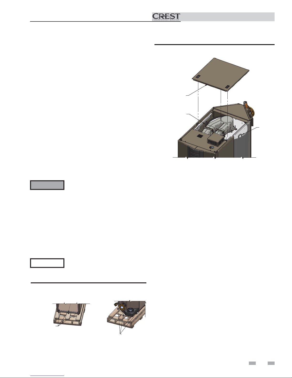
Figure 1-3 Boiler Removed from Shipping Pallet
REMOVE MIDDLE
TOP COVER
LIFTING
LUGS
LIFTING
LUGS
d. If lifting by crane is desired, remove the top access
panels to gain access to the lifting lugs located on the
boiler (see FIG. 1-3). It is also recommended that the
upper and lower front panels along with both front
side panels be removed (no tools required).
NOTICE
Do not drop the boiler or bump the jacket
on the floor or pallet. Damage to the
boiler can result.
Figure 1-2 Boiler Mounted on Shipping Pallet
BOLT, WASHERS
& LOCKNUT (3X)
FRONT
REAR
LAG BOLTS & TABS
(3X)
11
Page 12
1 Determine boiler location
Combustion and ventilation air
requirements for appliances drawing air
from the equipment room
Provisions for combustion and ventilation air must be in
accordance with Air for Combustion and Ventilation, of the
latest edition of the National Fuel Gas Code, NFPA 54 / ANSI
Z223.1, in Canada, the latest edition of CGA Standard B149
Installation Code for Gas Burning Appliances and Equipment,
or applicable provisions of the local building codes.
The equipment room MUST be provided with properly sized
openings and/or be of sufficient volume to assure adequate
combustion air and proper ventilation for all gas fired appliances
in the equipment room to assure adequate combustion air and
proper ventilation.
The requirements shown are for the appliance only; additional
gas fired appliances in the equipment room will require an
increase in the net free area and/or volume to supply adequate
combustion air for all appliances.
Figure 1-5_Combustion Air Through Ducts
2. If combustion and ventilation air is taken from the
outdoors using a duct to deliver the air to the
equipment room, each of the two openings should be
sized based on a minimum free area of one square inch
per 2000 Btu/hr (11 cm2 per kW) of input (see FIG. 1-5).
Installation & Operation Manual
No combustion air openings are needed when the appliance is
installed in a space with a volume NO LESS than 50 cubic feet
per 1,000 Btu/hr of all installed gas fired appliances and the
building MUST NOT be of “Tight Construction”3.
A combination of indoor and outdoor combustion air may
be utilized by applying a ratio of available volume to required
volume times the required outdoor air opening(s) size(s). This
must be done in accordance with the National Fuel Gas Code,
NFPA 54 / ANSI Z223.1.
Figure 1-6_Combustion Air from Interior Space
3. If air is taken from another interior space combined with
the equipment room:
(a) Two spaces on same story: Each of the two openings
specified above should have a net free area of one square
inch for each 1000 Btu/hr (22 cm2 per kW) of input, but
not less than 100 square inches (645 cm2) (see FIG. 1-6).
(b) Two spaces on different stories: One or more openings
should have a net free area of two square inches per 1000
Btu/hr (44 cm2 per kW).
Figure 1-4_Combustion Air Direct from Outside
1. If air is taken directly from outside the building
with no duct, provide two permanent openings to
the equipment room each with a net free area of one square
inch per 4000 Btu/hr input (5.5 cm2 per kW) (see FIG. 1-4).
12
Figure 1-7_Combustion Air from Outside - Single Opening
Page 13
1 Determine boiler location (continued)
Installation & Operation Manual
4. If a single combustion air opening is provided to bring
combustion air in directly from the outdoors, the
opening must be sized based on a minimum free area
of one square inch per 3000 Btu/hr (7 cm2 per kW). This
opening must be located within 12” (30 cm) of the top of
the enclosure (see FIG. 1-7).
Combustion air requirements are based on the latest edition
of the National Fuel Gas Code, NFPA 54 / ANSI Z223.1; in
Canada refer to the latest edition of CGA Standard CAN/CSA
B149.1. Check all local code requirements for combustion air.
All dimensions based on net free area in square inches. Metal
louvers or screens reduce the free area of a combustion air
opening a minimum of approximately 25%. Check with
louver manufacturers for exact net free area of louvers.
Where two openings are provided, one must be within 12"
(30 cm) of the ceiling and one must be within 12" (30 cm) of
the floor of the equipment room. Each opening must have a
net free area as specified in Table 1B. Single openings shall
commence within 12" (30 cm) of the ceiling. The minimum
dimension of air openings shall not be less than 3" (80 mm).
CAUTION
Under no circumstances should the
equipment room ever be under negative
pressure. Particular care should be taken
where exhaust fans, attic fans, clothes dryers,
compressors, air handling units, etc., may
take away air from the unit.
The combustion air supply must be completely free of any
flammable vapors that may ignite or chemical fumes which may
be corrosive to the appliance. Common corrosive chemical
fumes which must be avoided are fluorocarbons and other
halogenated compounds, most commonly present as refrigerants
or solvents, such as Freon, trichlorethylene, perchlorethylene,
chlorine, etc. These chemicals, when burned, form acids which
quickly attack the stainless steel heat exchanger, headers, flue
collectors, and the vent system.
The result is improper combustion and a non-warrantable,
premature appliance failure.
EXHAUST FANS: Any fan or equipment which exhausts air
from the equipment room may deplete the combustion air
supply and/or cause a downdraft in the venting system. Spillage
of flue products from the venting system into an occupied
living space can cause a very hazardous condition that must be
corrected immediately.
FIG. 1-4 FIG. 1-5 FIG. 1-6 FIG. 1-7
*Outside Air from
Model
Number
FB 1500
FB 2000
FB 2500
FB 3000
FB 3500
FB 4000
FB 5000
2 Openings Directly from
2
1
Bottom
Opening, in
(cm2)
375
(2420)
500
(3226)
625
(4033)
750
(4839)
875
(5646)
1000
(6450)
1250
(8062)
Outdoors
Top
Opening, in
(cm2)
375
(2420)
500
(3226)
625
(4033)
750
(4839)
875
(5646)
1000
(6450)
1250
(8062)
The above requirements are for the appliance only; additional gas fired appliances in the equipment room will require an increase
in the net free area and/or volume to supply adequate combustion air for all appliances.
No combustion air openings are needed when the appliance is installed in a space with a volume NO LESS than 50 cubic feet per
1,000 Btu/hr of all installed gas fired appliances. Buildings MUST NOT be of *“Tight Construction”3.
1
Outside air openings shall directly communicate with the outdoors.
2
Combined interior space must be 50 cubic feet per 1,000 Btu/hr input. Buildings MUST NOT be of *“Tight Construction”.
3
”Tight Construction” is defined as a building with less than 0.40 ACH (air changes per hour). For buildings of “Tight
Construction”, provide air openings into the building from outside.
TABLE - 1B
MINIMUM RECOMMENDED COMBUSTION
AIR SUPPLY TO EQUIPMENT ROOM
*Outside Air from
2 Ducts Delivered from
Outdoors
2
Top
Opening, in
(cm2)
750
(4839)
1000
(6452)
1250
(8065)
1500
(9678)
1750
(11291)
2000
(12900)
2000
(12900)
2
1
Bottom
Opening, in
(cm2)
750
(4839)
1000
(6452)
1250
(8065)
1500
(9678)
1750
(11291)
2000
(12900)
2000
(12900)
2 Ducts Delivered from Interior Space
2
Top
Opening, in
(cm2)
1500
(9678)
2000
(12904)
2500
(16129)
3000
(19355)
3500
(22581)
4000
(25800)
5000
(32250)
Inside Air from
Same Story
2
Bottom
Opening, in
(cm2)
1500
(9678)
2000
(12904)
2500
(16129)
3000
(19355)
3500
(22581)
4000
(25800)
5000
(32250)
Different
2
Opening, in
Stories
Total
(cm2)
3000
(19355)
4000
(25807)
5000
(32258)
6000
(38710)
7000
(45162)
8000
(51600)
10000
(64500)
2
*Outside Air from
1 Opening Directly
from Outdoors, in
(cm2)
2
500
(3226)
667
(4304)
833
(5381)
1000
(6452)
1167
(7530)
1333
(8600)
1667
(10750)
2
1
13
Page 14
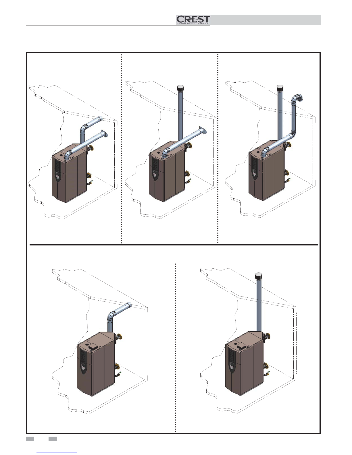
2 General venting
Installation & Operation Manual
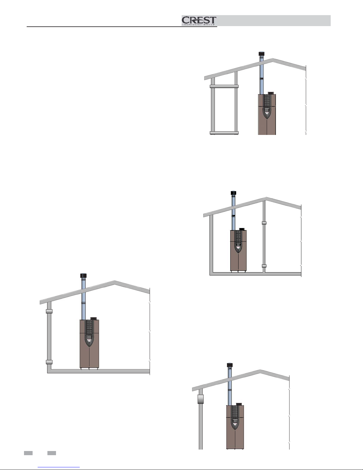
Direct venting
Sidewall
Vertical Vent, Sidewall Air
Optional room air
Vertical
Sidewall
14
Vertical
Page 15

2 General venting (continued)
Install vent and combustion air piping
Installation & Operation Manual
DANGER
The Crest must be vented and supplied
with combustion and ventilation air as
described in this section. Ensure the vent
and air piping and the combustion air
supply comply with these instructions
regarding vent system, air system, and
combustion air quality. See also Section
1 of this manual.
Inspect finished vent and air piping
thoroughly to ensure all are airtight and
comply with the instructions provided
and with all requirements of applicable
codes.
Failure to provide a properly installed
vent and air system will cause severe
personal injury or death.
Air inlet pipe materials:
The air inlet pipe(s) must be sealed. Choose acceptable
combustion air inlet pipe materials from the following list:
ABS, PVC, or CPVC
Dryer Vent or Sealed Flexible Duct (not recommended
for rooftop air inlet)
Galvanized steel vent pipe with joints and seams sealed
as specified in this section.
Type “B” double-wall vent with joints and seams sealed
as specified in this section.
AL29-4C, stainless steel material to be sealed to
specification of its manufacturer.
Sealing of Type “B” double-wall vent material or galvanized
vent pipe material used for air inlet piping on a sidewall or
vertical rooftop Combustion Air Supply System:
a. Seal all joints and seams of the air inlet pipe using either
Aluminum Foil Duct Tape meeting UL Standard 723 or
181A-P or a high quality UL Listed silicone sealant such
as those manufactured by Dow Corning or General
Electric.
b. Do not install seams of vent pipe on the bottom of
horizontal runs.
c. Secure all joints with a minimum of three sheet metal
screws or pop rivets. Apply Aluminum Foil Duct Tape or
silicone sealant to all screws or rivets installed in the vent
pipe.
d. Ensure that the air inlet pipes are properly supported.
The PVC, CPVC, or ABS air inlet pipe should be cleaned and
sealed with the pipe manufacturer’s recommended solvents
and standard commercial pipe cement for the material used.
The ABS, PVC, CPVC, Dryer Vent or Flex Duct air inlet pipe
should use a silicone sealant to ensure a proper seal at the
appliance connection and the air inlet cap connection. Dryer
vent or flex duct should use a screw type clamp to seal the
vent to the appliance air inlet and the air inlet cap. Proper
sealing of the air inlet pipe ensures that combustion air will be
free of contaminants and supplied in proper volume.
*Plastic pipe may require an adapter (not provided) to
transition between the air inlet connection on the appliance
and the plastic air inlet pipe.
WARNING
NOTICE
Using vent or air intake materials other
than those specified, failure to properly
seal all seams and joints or failure to follow
vent pipe manufacturer’s instructions can
result in personal injury, death or property
damage. Mixing of venting materials will
void the warranty and certification of the
appliance.
The use of double-wall vent or insulated
material for the combustion air inlet
pipe is recommended in cold climates
to prevent the condensation of airborne
moisture in the incoming combustion air.
15
Page 16
2 General venting
Installation & Operation Manual
When a sidewall or vertical rooftop combustion air supply
system is disconnected for any reason, the air inlet pipe must
be resealed to ensure that combustion air will be free of
contaminants and supplied in proper volume.
DANGER
Failure to properly seal all joints and seams
as required in the air inlet piping may
result in flue gas recirculation, spillage
of flue products and carbon monoxide
emissions causing severe personal injury
or death.
Vent and air piping
This product has been approved for use with stainless steel
vent systems.
WARNING
NOTICE
NOTICE
Use only the materials, vent systems, and
terminations listed in Table 2A. DO
NOT mix vent systems of different types
or manufacturers, unless listed in this
manual. Failure to comply could result
in severe personal injury, death, or
substantial property damage.
Installations must comply with applicable
national, state, and local codes. Stainless
steel vent systems must be listed as a
UL-1738 approved system for the United
States and a ULC-S636 approved system
for Canada.
Installation of a stainless steel vent system
should adhere to the stainless steel vent
manufacturer’s installation instructions
supplied with the vent system.
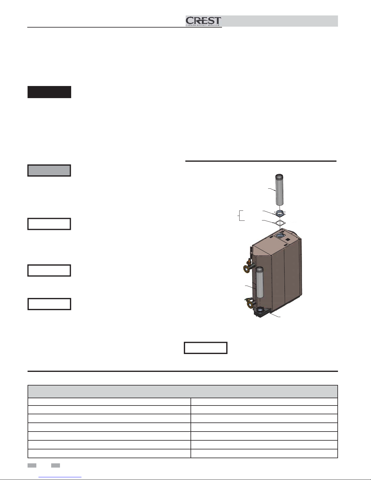
Air intake/vent connections
1. Combustion Air Intake Connector (FIG. 2-1) - Used to
provide combustion air directly to the unit from outdoors.
A fitting is provided with the unit for final connection.
Combustion air piping must be supported per guidelines
listed in the National Mechanical Code, Section 305, Table
305.4 or as local codes dictate.
2. Vent Connector (FIG. 2-1) - Used to provide a
passageway for conveying combustion gases to the
outside. A transition fitting is provided on the unit for
final connection. Vent piping must be supported per the
National Building Code, Section 305, Table 305.4 or as
local codes dictate.
Figure 2-1 Combustion Air Adapter
AIR PIPE
(FIELD SUPPLIED)
SHIPPED LOOSE
WITH THE BOILER
VENT PIPE
(FIELD SUPPLIED)
ADAPTER
GASKET
NOTICE
The Crest is supplied with an integral
FasNSeal vent connector (FIG. 2-1). The
installer must use a specific vent starter
adapter supplied by the vent manufacturer
to adapt to different vent systems.
Table 2A Approved Stainless Steel Vent Manufacturers
Approved Stainless Steel Vent Manufacturers
Make Model
ProTech Systems (Simpson Dura-Vent Co.) FasNSeal Vent
Z-Flex (Nova Flex Group) Z-Vent
Heat Fab (Selkirk Corporation) Saf-T Vent
Metal Fab Corr/Guard
Securities Chimneys International Secure Seal SS
Schebler Chimney Systems eVent
16
CONNECTOR
The Crest uses model specific combustion air intake and vent
piping sizes as detailed in Tables 2B and 2C on page 17.
NOTICE
Increasing or decreasing combustion air
or vent piping to sizes not specified in this
manual is not authorized.
Page 17
Installation & Operation Manual
2 General venting (continued)
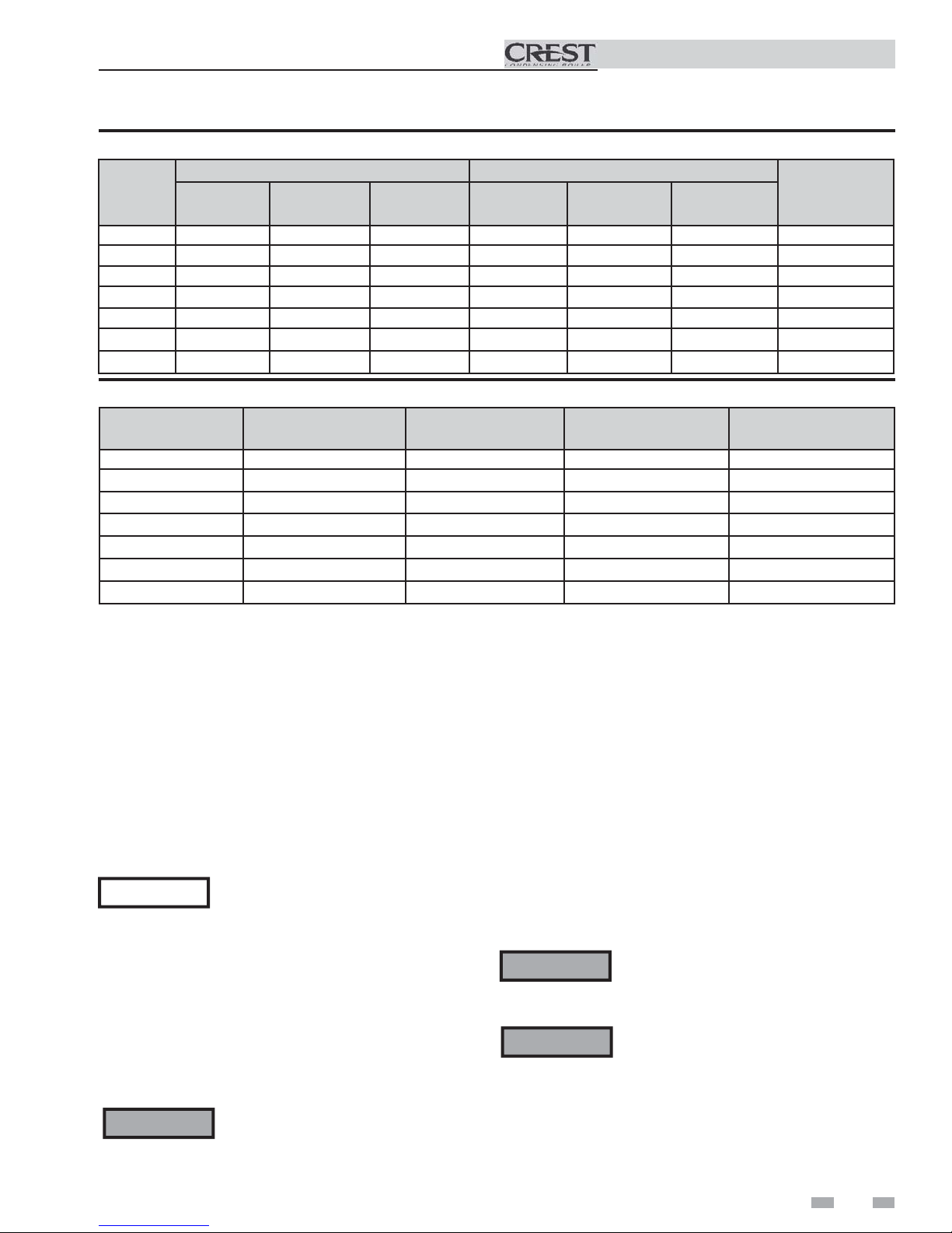
Table 2B Direct Vent Minimum / Maximum Allowable Air / Vent Lengths
AIR INLET VENT
Model
FB 1500 7" 12' 100' 7" 12' 100' 2%
FB 2000 8" 12' 100' 8" 12' 100' 2%
FB 2500 8" 12' 100' 9" 12' 100' 2%
FB 3000 10" 12' 100' 10" 12' 100' 2%
FB 3500 10" 12' 100' 10" 12' 100' 2%
FB 4000 12" 12' 100' 12" 12' 100' 0.5%
FB 5000 14" 12' 100' 14" 12' 100' 0%
Table 2C Room Air Minimum / Maximum Allowable Air / Vent Lengths
Air Intake
Diameter
Air Intake
Min. Length
Air Intake
Max. Length
Vent
Diameter
Vent
Min. Length
Vent
Max. Length
De-Rate per
25 feet of Vent
Input
Model
FB 1500 7" 12' 100' 1%
FB 2000 8" 12' 100' 1%
FB 2500 9" 12' 100' 1%
FB 3000 10" 12' 100' 1%
FB 3500 10" 12' 100' 1%
FB 4000 12" 12' 100' 0%
FB 5000 14" 12' 100' 0%
When determining equivalent combustion air and vent
length, add 5 feet (1.5m) for each 90° elbow and 3 feet (.9 m)
for each 45° elbow.
EXAMPLE: 20 feet (6 m) of pipe + (4) 90° elbows + (3) 45°
elbows = 49 equivalent feet (15 m) of piping.
Vent
Diameter
Removing from existing vent
Follow the instructions in Section 1, page 10 of this manual
when removing a boiler from an existing vent system.
Vent and air piping
Vent and air system:
NOTICE
You must also install air piping from outside to the boiler
air intake adapter. The resultant installation is direct vent
(sealed combustion).
You may use any of the vent/air piping methods covered in
this manual. Do not attempt to install the Crest using any
other means.
WARNING
Installation must comply with local
requirements and with the National Fuel
Gas Code, NFPA 54 / ANSI Z223.1 for U.S.
installations or CSA B149.1 for Canadian
installations.
DO NOT mix components from different
systems. The vent system could fail,
causing leakage of flue products into the
living space. Use only approved stainless
steel pipe and fittings.
Vent
Min. Length
Vent, air piping and termination:
The Crest vent and air piping can be installed through the roof
or through a sidewall. Follow the procedures in this manual for
the method chosen. Refer to the information in this manual to
determine acceptable vent and air piping length.
Air contamination
Pool and laundry products and common household and hobby
products often contain fluorine or chlorine compounds. When
these chemicals pass through the boiler, they can form strong
acids. The acid can eat through the boiler wall, causing serious
damage and presenting a possible threat of flue gas spillage or
boiler water leakage into the building.
Please read the information given in Table 1A, page 9,
listing contaminants and areas likely to contain them. If
contaminating chemicals will be present near the location of the
boiler combustion air inlet, have your installer pipe the boiler
combustion air and vent to another location, per this manual.
WARNING
WARNING
Vent
Max. Length
If the boiler combustion air inlet is located
in a laundry room or pool facility, for
example, these areas will always contain
hazardous contaminants.
To prevent the potential of severe personal
injury or death, check for areas and products
listed in Table 1A, page 9 before installing
the boiler or air inlet piping.
If contaminants are found, you MUST:
• Remove products permanently.
—OR—
• Relocate air inlet and vent
terminations to other areas.
Input De-Rate per
25 feet of Vent
17
Page 18
2 General venting
Common venting
Installation & Operation Manual
Crest boilers may be common vented; however, the following
criteria MUST BE followed:
1. Only Crest boilers may be connected to the common
vent. DO NOT mix other manufacturer’s appliances or
other Lochinvar models.
2. Crest boilers connected to the common vent must all be
of the same size.
3. Each Crest boiler must have a Lochinvar supplied flue
damper installed (see Table 2D).
4. Only vertical direct vent, positive pressure, Category
IV or vertical/chimney vent, negative pressure, Category
II may be used when common venting Crest boilers.
Sidewall venting is not allowed.
5. Crest boilers in a common vent must be connected and
controlled with the integral Crest SMART TOUCH
Cascade.
a. The Leader may be controlled through the Crest
SMART TOUCH control through BMS (external
0 - 10V signal), ModBus or its own internally
calculated set point.
Table 2D Flue Damper Kits
Flue Damper Kits
Model Damper Size Kit Number
FB1500 7" DRH30000
FB2000 8" DRH30001
FB2500 9" DRH30002
FB3000 10" DRH30003
FB3500 10" DRH30003
FB4000 12" DRH30004
FB5000 14" DRH30005
b. The Cascade (Members) must be controlled by the
Crest Leader boiler using the Lead/Lag Cascade
option.
For approved common vent sizing, contact the factory.
WARNING
When Crest boilers are common vented,
the criteria above MUST BE followed.
Failure to follow all these requirements
will result in severe personal injury, death,
or substantial property damage.
18
Page 19
3 Vertical direct venting
A
A
Vent/air termination – vertical
Installation & Operation Manual
WARNING
Follow instructions below when determining
vent location to avoid possibility of severe
personal injury, death or substantial property
damage.
WARNING
Do not connect any other appliance to the
vent pipe or multiple boilers to a common
vent pipe except as noted in Section 2 on
page 18. Failure to comply could result in
severe personal injury, death, or substantial
property damage.
NOTICE
Installation must comply with local
requirements and with the National Fuel
Gas Code, NFPA 54 / ANSI Z223.1 - latest
edition for U.S. installations or CSA B149.1
Installation Code for Canadian installations.
Determine location
Locate the vent/air terminations using the following guidelines:
1. The total length of piping for vent or air must not exceed
the limits given in the General Venting Section on page 17
of this manual.
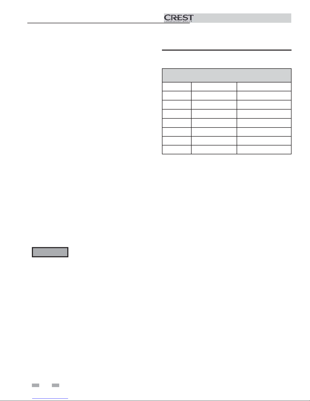
2. The vent must terminate at least 3 feet above the highest
place in which the vent penetrates the roof and at least 2 feet
above any part of a building within 10 horizontal feet.
3. The air piping must terminate in a down-turned 180°
return pipe no further than 2 feet (.6 m) from the center of
the vent pipe. This placement avoids recirculation of flue
products into the combustion air stream.
4. The vent piping must terminate in an up-turned coupling
as shown in FIG. 3-1. The top of the coupling or the rain
cap must be at least 36" (914 mm) above the air intake. The
air inlet pipe and vent pipe can be located in any desired
position on the roof, but must always be no further than 2
feet (.6 m) apart and with the vent termination at least 36"
(914 mm) above the air intake.
WARNING
Rooftop vent and air inlet terminations
must terminate in the same pressure zone,
unless vertical vent sidewall air is set up as
shown in the General Venting - Vertical
Vent, Sidewall Air Section.
Figure 3-2 Vertical Termination of Air and Vent w/Rain
Cap
BIRD SCREEN
[TYPICAL]
VENT OUTLET
36" [914 MM] MINIMUM
BOVE AIR INLET
12" [305 MM] MINIMUM
ABOVE ROOF /
SNOW LINE
5. Locate terminations so they are not likely to be damaged
by foreign objects, such as stones or balls, or subject to
buildup of leaves or sediment.
Prepare roof penetrations
1. Air pipe penetration:
a. Cut a hole for the air pipe. Size the air pipe hole as
close as desired to the air pipe outside diameter.
2. Vent pipe penetration:
a. Cut a hole for the vent pipe. For either combustible
or noncombustible construction, size the vent pipe
hole per the vent manufacturer’s instructions.
b. Insert a galvanized metal thimble in the vent pipe
hole (when required by local codes).
3. Space the air and vent holes to provide the minimum
spacing shown in FIG. 3-1.
4. Follow all local codes for isolation of vent pipe when
passing through floors, ceilings, and roofs.
5. Provide flashing and sealing boots sized for the vent pipe
and air pipe.
Termination and fittings
Figure 3-1 Vertical Termination of Air and Vent
VENT OUTLET
36" MINIMUM
BOVE AIR INLET
VENT
COMBUSTION AIR
BIRD SCREEN
[TYPICAL]
12" [305 MM] MINIMUM
ABOVE ROOF /
SNOW LINE
1. Prepare the vent termination coupling and the air
termination elbow (FIG. 3-1) by inserting bird screens.
Bird screens should be obtained locally.
2. The air piping must terminate in a down-turned 180°
return bend as shown in FIG. 3-1. Locate the air inlet
pipe no further than 2 feet (.6 m) from the center of the
vent pipe. This placement avoids recirculation of flue
products into the combustion air stream.
19
Page 20
3 Vertical direct venting
Installation & Operation Manual
3. The vent piping must terminate in an up-turned coupling
as shown in FIG. 3-1. The top of the coupling or the
rain cap must be at least 36" (914 mm) above the air
intake. The air inlet pipe and vent pipe can be located
in any desired position on the roof, but must always be
no further than 2 feet (.6 m) apart and with the vent
termination at least 36" (914 mm) above the air intake.
4. Maintain the required dimensions of the finished
termination piping as shown in FIG. 3-1.
5. Do not extend exposed vent pipe outside of building
more than shown in this document. Condensate could
freeze and block vent pipe.
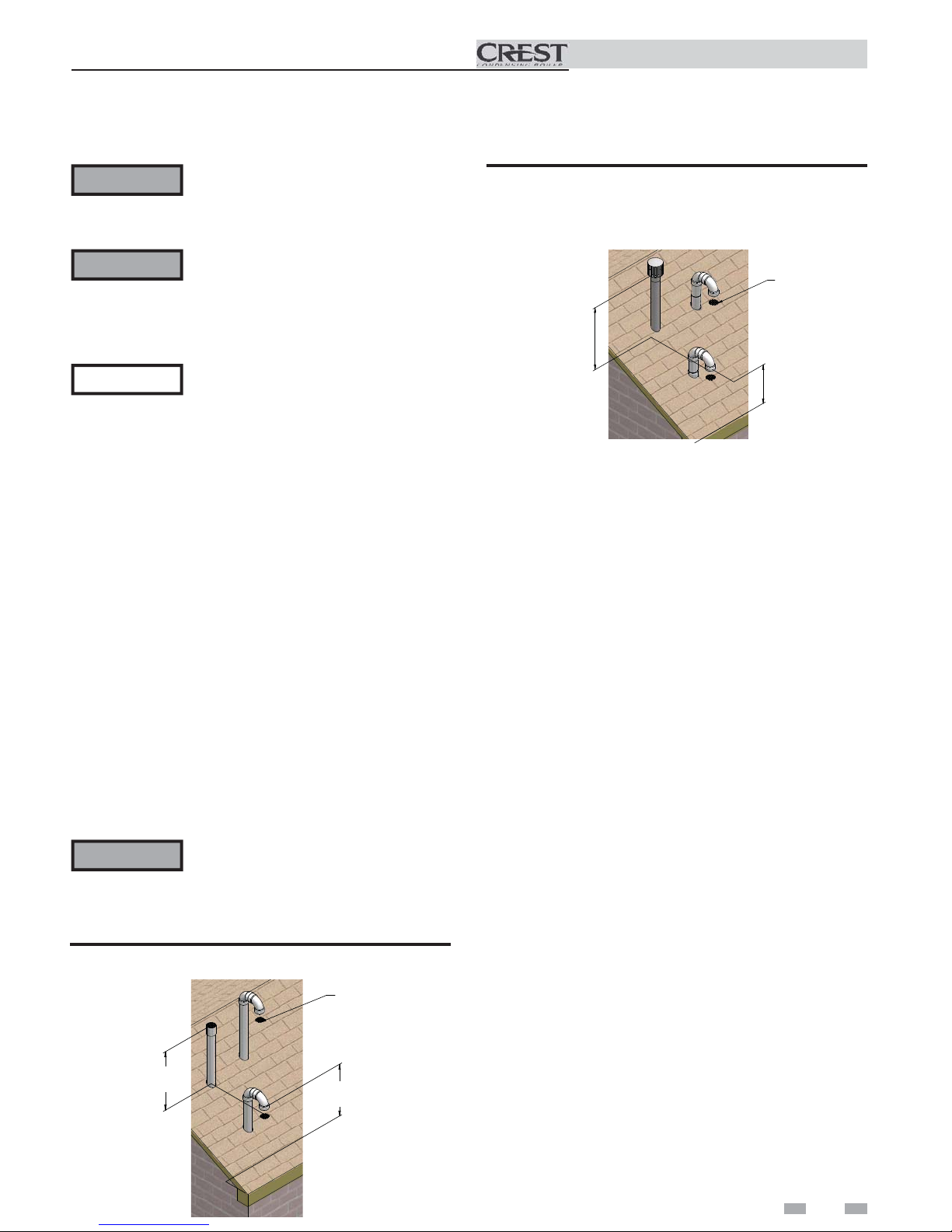
Multiple vent/air terminations
1. When terminating multiple Crest boilers, terminate
each vent/air connection as described in this manual
(FIG. 3-3).
WARNING
Terminate all vent pipes at the same height
and all air pipes at the same height to
avoid recirculation of flue products and
the possibility of severe personal injury,
death, or substantial property damage.
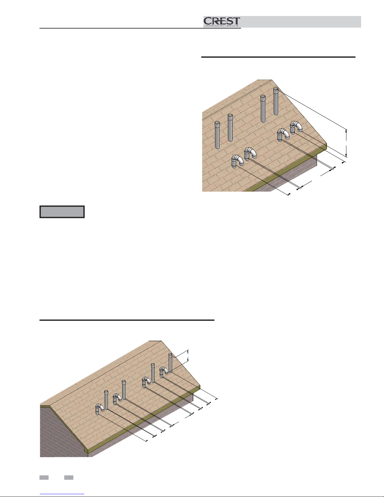
Figure 3-4 Alternate Vertical Terminations with Multiple
Boilers
36” (914 MM)
12”
(305 MM)
36” (914 MM)
12”
(305 MM)
2. Place roof penetrations to obtain minimum clearance of
12 inches (305 mm) between edge of air intake elbow and
adjacent vent pipe of another boiler for U.S. installations
(see FIG. 3-3). For Canadian installations, provide
clearances required by CSA B149.1 Installation Code.
3. The air inlet of a Crest boiler is part of a direct vent
connection. It is not classified as a forced air intake with
regard to spacing from adjacent boiler vents.
Figure 3-3 Vertical Terminations with Multiple Boilers
36” (914 MM)
36” (914 MM)
12”
(305 MM)
12”
(305 MM)
12”
(305 MM)
12”
(305 MM)
12”
(305 MM)
12”
(305 MM)
20
Page 21

4 Sidewall direct venting
Vent/air termination – sidewall
Installation & Operation Manual
WARNING
Follow instructions below when
determining vent location to avoid
possibility of severe personal injury, death,
or substantial property damage.
WARNING
A gas vent extending through an exterior
wall shall not terminate adjacent to a wall
or below building extensions such as eaves,
parapets, balconies, or decks. Failure to
comply could result in severe personal
injury, death, or substantial property
damage.
WARNING
Do not connect any other appliance to the
vent pipe or multiple boilers to a common
vent pipe except as noted in Section 2
on page 18. Failure to comply could
result in severe personal injury, death, or
substantial property damage.
CAUTION
Sidewall venting commercial products will
result in large exhaust plumes in cold
climates. Consideration should be taken
when locating in proximity to windows,
doors, walkways, etc.
NOTICE
Installation must comply with local
requirements and with the National Fuel
Gas Code, NFPA 54 / ANSI Z223.1 for U.S.
installations or CSA B149.1 for Canadian
installations.
Determine location
Locate the vent/air terminations using the following
guidelines:
1. The total length of piping for vent or air must not exceed
the limits given in the General Venting Section on page
17 of this manual.
2. You must consider the surroundings when terminating
the vent and air:
a. Position the vent termination where vapors will
not damage nearby shrubs, plants or air
conditioning equipment or be objectionable.
b. The flue products will form a noticeable plume as
they condense in cold air. Avoid areas where the
plume could obstruct window views.
c. Prevailing winds could cause freezing of condensate
and water/ice buildup where flue products impinge
on building surfaces or plants.
d. Avoid possibility of accidental contact of flue
products with people or pets.
e. Do not locate the terminations where wind eddies
could affect performance or cause recirculation,
such as inside building corners, near adjacent
buildings or surfaces, window wells, stairwells,
alcoves, courtyards, or other recessed areas.
WARNING
Sidewall vent and air inlet terminations
must terminate in the same pressure
zone.
f. Do not terminate above any door or above or
below any window. Condensate can freeze, causing
ice formations.
g. Locate or guard vent to prevent condensate
damage to exterior finishes.
Figure 4-1 Sidewall Termination of Air and Vent
NOTICE
PVC/CPVC or ABS is acceptable air inlet pipe material.
FROM BOILER VENT
PIPE CONNECTION
TO BOILER INTAKE
AIR CONNECTION
36" MIN
48" MAX
12" MIN
GRADE OR
SNOW LINE
3. Maintain clearances as shown in FIG.’s 4-1 thru 4-3,
pages 21 and 22. The vent termination should not be
located in traffic areas such as walkways, adjacent
buildings, operable windows, or doors. Also maintain
the following:
a. Vent must terminate:
• At least 6 feet (1.8 m) from adjacent walls.
• Not less than 7 feet (2.1 m) above grade where located
adjacent to public walkways.
• No closer than 12 inches (305 mm) below roof
overhang.
• At least 3 feet (.9 m) above any forced air intake
within 10 feet (3 m).
• No closer than 4 feet (1.2 m) horizontally
from any door or window or any other gravity air
inlet.
b. Air inlet must terminate at least 12 inches (305 m)
above grade or snow line; at least 36 inches
(914 mm) below the vent termination.
c. Do not terminate closer than 4 feet (1.2 m)
horizontally from any electric meter, gas meter,
regulator, relief valve, or other equipment. Never
terminate above or below any of these within 4 feet
(1.2 m) horizontally.
4. Locate terminations so they are not likely to be damaged
by foreign objects, such as stones or balls, or subject to
buildup of leaves or sediment.
21
Page 22

4 Sidewall direct venting
Vent/air termination – sidewall
Installation & Operation Manual
Figure 4-2 Clearance to Doors and Windows
4'
4'
Figure 4-3 Clearance to Forced Air Inlets
IF LESS THAN 10’
VENT TERMINATION
Prepare wall penetrations
1. Air pipe penetration:
a. Cut a hole for the air pipe. Size the air pipe hole as
close as desired to the air pipe outside
diameter.
Vent pipe penetration:
a. Cut a hole for the vent pipe. For either combustible
or noncombustible construction, size the vent pipe
hole per the vent manufacturer’s instructions.
2. Install the vent and air intake piping. Seal all gaps
between the pipes and wall with RTV silicone sealant.
3. Seal all wall cavities.
Termination and fittings
1. The air termination must be oriented at least 12 inches
above grade or snow line as shown in FIG. 4-1, page
21.
2. Maintain the required dimensions of the finished
termination piping as shown in FIG. 4-1, page 21.
3. Do not extend exposed vent pipe outside of the
building more than what is shown in this document.
Condensate could freeze and block vent pipe.
4. Stainless steel terminations are designed to penetrate
walls with a thickness up to 9.25 inches of standard
construction.
36” MIN.
Multiple vent/air terminations
AIR TERMINATION
CAUTION
Sidewall venting commercial products will
result in large exhaust plumes in cold
climates. Consideration should be taken
when locating in proximity to windows,
doors, walkways, etc.
22
FORCED AIR
INLET
1. When terminating multiple Crest boilers terminate
each vent/air connection as described in this manual
(FIG. 4-4).
WARNING
All vent pipes and air inlets must
terminate at the same height to avoid
possibility of severe personal injury,
death, or substantial property damage.
Page 23

4 Sidewall direct venting (continued)
Installation & Operation Manual
2. Place wall penetrations to obtain minimum clearance
of 12 inches (305 mm) between vent pipe and adjacent
air inlet, as shown in FIG. 4-4 for U.S. installations. For
Canadian installations, provide clearances required by
CSA B149.1 Installation Code.
3. The air inlet of a Crest is part of a direct vent
connection. It is not classified as a forced air intake
with regard to spacing from adjacent boiler vents.
Figure 4-4 Multiple Vent Terminations (must also
comply with Figure 4-1)
12"
36" MIN
48" MAX
12"
12" MIN
36"
Figure 4-5 Direct Vent Terminations
VENT
AIR
Figure 4-6 Room Air (Direct Exhaust Terminations)
ROOM AIR (DIRECT EXHAUST TERMINATIONS)
Vent Termination
23° Elbow
45° Elbow
90° Elbow
Room air
The Crest boiler may be installed with a single pipe carrying the
flue products to the outside while using combustion air from
the equipment room.
Follow the requirements in the General Venting, Sidewall Direct
Venting, and Vertical Direct Venting sections for vent material
specifications, vent length requirements, and vent termination
requirements.
Install the air inlet cover (shipped loose with the boiler) per
FIG. 4-7. Combustion and ventilation air must be supplied to
the equipment room per the requirements on pages 12 and 13
of this manual for proper operation of the Crest boiler when
utilizing the single pipe method.
DIRECT VENT TERMINATIONS
Air Inlet Vent Termination
Dryer Inlet Straight
90° Elbow Mitered
23° Elbow
Figure 4-7 Room Air Installation
AIR INLET COVER
23
Page 24

5 Hydronic piping
Installation & Operation Manual
System water piping methods
The Crest is designed to function in a closed loop pressurized
system not less than 12 psi (83 kPa). A temperature and
pressure gauge is included to monitor system pressure and
outlet temperature and should be located on the boiler outlet.
It is important to note that the boiler has a pressure drop
which must be figured in when sizing the circulators. Each
boiler installation must have an air elimination device, which
will remove air from the system.
Install the boiler so the gas ignition system components
are protected from water (dripping, spraying, etc.) during
appliance operation or basic service of circulator replacement,
valves, and others.
Observe a minimum of 1/4 inch (6 mm) clearance around all
uninsulated hot water pipes when openings around the pipes
are not protected by non-combustible materials.
Low water cutoff device
An electronic low water cutoff is provided as standard
equipment on all models. The low water cutoff should be
inspected every 6 months.
Chilled water system
If the boiler supplies hot water to heating coils in air handler
units, flow control valves or other devices must be installed to
prevent gravity circulation of heater water in the coils during
the cooling cycle. A chilled water medium must be piped in
parallel with the heater.
Freeze protection
Freeze protection for new or existing systems must use glycol
that is specially formulated for this purpose. This includes
inhibitors, which prevent the glycol from attacking the
metallic system components. Make certain to check that
the system fluid is correct for the glycol concentration and
inhibitor level. The system should be tested at least once
a year and as recommended by the producer of the glycol
solution. Allowance should be made for the expansion of the
glycol solution in the system piping.
WARNING
Use only inhibited propylene glycol
solutions, which are specifically formulated
for hydronic systems. Ethylene glycol is
toxic and can attack gaskets and seals used
in hydronic systems.
General piping information
Basic steps are listed below along with illustrations on the
following pages, which will guide you through the installation
of the Crest (5-2 thru 5-5).
1. Connect the system return to the 4" flanged connection
marked “Inlet”, make sure to install with a suitable gasket
between flanges.
2. Connect the system supply to the 4" flanged connection
marked “Outlet”, make sure to install with a suitable gasket
between flanges.
3. Install purge and balance valve or shutoff valve and drain
on system return to purge air out of each zone.
4. Install a backflow preventer on the cold feed make-up water
line.
5. Install a pressure reducing valve on the cold feed make-up
water line, (15 psi (103 kPa) nominal). Check temperature
and pressure gauge, which should read a minimum pressure
of 12 psi (83 kPa).
6. Install the circulators as shown on the piping diagrams in
this section. Make sure the circulators are properly sized
for the system and friction loss. Install check valves with
each boiler circulator.
7. Install an expansion tank on the system supply. Consult the
tank manufacturer’s instruction for specific information
relating to tank installation. Size the expansion tank for the
required system volume and capacity.
8. Install an air elimination device on the system supply.
9. This appliance is supplied with a relief valve sized in
accordance with ASME Boiler and Pressure Vessel Code,
Section IV (“Heating Boilers”). The safety relief valve
is installed at the factory and is located on the rear of
the boiler. Pipe the discharge of the safety relief valve to
prevent injury in the event of pressure relief. Pipe the
discharge to a drain. Provide piping that is the same size as
the safety relief valve outlet. Never block the outlet of the
safety relief valve.
10. On any pre-existing system, it is good practice to install
a field supplied strainer to prevent damage to the heat
exchanger.
See the piping illustrations included in this section, FIG.’s 5-2
thru 5-5 for suggested guidelines in piping the Crest.
NOTICE
Please note that these illustrations are meant
to show system piping concept only, the
installer is responsible for all equipment and
detailing required by local codes.
24
Page 25

Installation & Operation Manual
0.00
1.00
2.00
3.00
4.00
5.00
6.00
7.00
8.00
9.00
10.00
11.00
12.00
13.00
14.00
15.00
16.00
17.00
18.00
20 40 60 80 100 120 140 160 180 200 220 240 260 280 300 320 340
Pressure Drop (Feet of Head)
Flow Rate (GPM)
CREST Pressure Drop Curve
FB1500
FB2000
FB2500
FB3000
FB3500
FB4000
FB5000
5 Hydronic piping (continued)
Circulator sizing
The Crest heat exchanger does have a pressure drop, which must be considered in your system design. Refer to the graph in
FIG. 5-1 for pressure drop through the Crest heat exchanger.
Figure 5-1 Pressure Drop vs. Flow
Table 5A Sizing Information for Temperature Rise Applications_20°F, 40°F and 60°F
Model
FB 1500 4" 138 3.4 69 1.0 46 0.5
FB 2000 4" 184 4.1 92 1.2 61 0.6
FB 2500 4" 230 4.6 115 1.4 77 0.7
FB 3000 4" 276 5.6 138 1.7 92 0.8
FB 3500 4" 322 7.5 161 2.2 107 1.1
FB 4000 4" 248* 4.2 186 1.8 124 0.9
FB 5000 4" 310* 4.5 233 0.9 155 0.5
[Models FB 1500 - 3500 based on 92% AHRI Effi ciency and Models FB 4000 - 5000 based on 93% Effi ciency]
*Flow is based on 30°FT.
NOTICE
BOILER
CONNECTION SIZE
The pressure drop reflected in FIG. 5-1 is
for the boiler only. Additional allowances
must be made for piping, especially if
sizing pumps for Primary/Secondary
applications.
TEMPERATURE RISE APPLICATIONS
20°F 40°F 60°F
GPM FT/HD GPM FT/HD GPM FT/HD
NOTICE
It is required that boiler piping systems
utilize Primary/Secondary or Fixed or
Variable Flow Primary configurations as
shown in FIG.’s 5-2 thru 5-5. The use of
other boiler piping configurations could
result in improper building and system flow
rates leading to inadvertent boiler high limit
shutdowns and poor system performance.
25
Page 26

5 Hydronic piping
Installation & Operation Manual
Near boiler piping components
1. Boiler piping:
Boiler system piping should be sized per the pipe
requirements listed in Tables 5A and 5C.
2. Boiler circulating pump:
Field supplied. When using Primary/Secondary piping the
boiler circulating pump should be sized per Table 5A.
3. Hot Water Generator circulating pump:
Field supplied. When installed in a Primary/Secondary
arrangement, the Crest requires an additional pump for
the Hot Water Generator Loop. The pump should
be sized per Table 5A. Consult the indirect water
heater operating guide to determine flow characteristics
for the selected product used. The pump’s total flow and
heat requirements are the sum of the boiler and the indirect
water heater.
4. Boiler isolation valves:
Field supplied. Full port valves are required. Failure
to use full port valves could result in a restricted flow
rate through the boiler.
5. Check valves:
Field supplied. Check valves are required for
installation as shown in FIG.’s 5-2 and 5-3. Failure to
install check valves could result in a reverse flow
condition during pump(s) off cycle.
6. Domestic indirect hot water isolation valves:
Field supplied. Full port valves are required. Failure to use
full port valves could result in a restricted flow rate through
the boiler.
NOTICE
10. Y-Strainer:
Field supplied. A Y-strainer or equivalent multipurpose
strainer is recommended at the inlet of the heat
exchanger to remove system particles from older
hydronic systems and protect newer systems.
CAUTION
NOTICE
Table 5B1 Minimum Flow Rate with the Boiler at Full Fire
TEMPERATURE RISE APPLICATIONS
MODEL FLOW RATE (GPM)
FB(N,L)1500 35
FB(N,L)2000 46
FB(N,L)2500 58
FB(N,L)3000 70
FB(N,L)3500 81
A system supply sensor (factory supplied)
MUST BE installed with Primary/Secondary
systems for proper boiler operation.
The maximum allowable water flow rate
through a single Crest boiler is 350 GPM.
Exceeding this flow rate will result in damage
to the heat exchanger and/or piping.
Reference Table 5B1 for the minimum
recommended flow rate through a single
Crest boiler at full fire to maintain a 80°F
temperature rise. Reference Table 5B2 for
the absolute minimum flow rate through a
single Crest boiler.
7. Anti-scald mixing valve:
Field supplied. An anti-scald mixing valve is
recommended when storing domestic hot water above
115°F (46°C).
8. Pressure relief valve:
Factory supplied. The pressure relief valve is sized to
ASME specifications.
9. System temperature sensor:
Lochinvar supplies a system temperature sensor.
The sensor is to be installed in the heating loop
downstream from the boiler hot water piping and
heating loop junction. The sensor should be
located far enough downstream to sense system diluted
water temperature.
26
FB(N,L)4000 92
FB(N,L)5000 115
[Based on 80°F Temperature Rise]
Table 5B2 Absolute Minimum Flow Rate
ABSOLUTE MINIMUM FLOW RATE
MODEL FLOW RATE (GPM)
FB(N,L)1500 25
FB(N,L)2000 25
FB(N,L)2500 25
FB(N,L)3000 25
FB(N,L)3500 45
FB(N,L)4000 45
FB(N,L)5000 50
Page 27

Installation & Operation Manual
5 Hydronic piping (continued)
Figure 5-2 Single Boiler - Recommended - Primary / Secondary Piping with a Hot Water Generator
FROM SYSTEM
SYSTEM RETURN
SENSOR
12"
MAX
HOT WATER
GENERATOR
RELIEF
VALVE
BALL VALVE
(TYPICAL)
AIR SEPERATOR
DRAIN PORT
(TYPICAL)
SYSTEM SUPPLY
SENSOR
SYSTEM
CIRCULATOR
WATER
GENERATOR
CIRCULATOR
BOILER PUMP
NOTICE
NOTICE
TO SYSTEM
BOILER
DRAIN
FLOW CHECK
VALVE (TYPICAL)
Y-STRAINER
(RECOMMENDED)
EXPANSION
TANK
PRESSURE
REDUCING VALVE
PRESSURE
GAUGE
BACK FLOW
PREVENTER
MAKE UP
WATER
System flow should always remain higher than the required flow for the boiler(s) when the boiler(s) is in
operation to prevent short cycling and high limit issues.
Please note that these illustrations are meant to show system piping concept only, the installer is responsible
for all equipment and detailing required by local codes.
27
Page 28

5 Hydronic piping
Table 5C Multiple Boilers - Common Header - Primary / Secondary Flow
Number of Units
Model
FB 1500
FB 2000
FB 2500
FB 3000
FB 3500
FB 4000
FB 5000
234567 8
Recommended Common Header Pipe Sizes in Inches
445566 7
455677 8
556778 10
567781010
5 6 7 8 10 10 10
6 6 8 8 10 10 12
68810101212
[Based on a boiler ΔT of 30°F.]
Installation & Operation Manual
NOTICE
A system supply sensor (factory supplied) MUST BE installed for proper boiler operation.
Figure 5-3 Multiple Boilers - Common Header - Recommended - Primary / Secondary Flow
FROM SYSTEM
SYSTEM RETURN
HOT WATER
GENERATOR
WATER
GENERATOR
CIRCULATOR
RELIEF
VALVE
BOILER DRAIN
(TYPICAL)
BOILER PUMP
(TYPICAL)
SENSOR
Y-STRAINER
(RECOMMENDED)
FLOW CHECK
VALVE (TYPICAL)
BALL VALVE
(TYPICAL)
AIR SEPARATOR
DRAIN PORT
(TYPICAL)
SYSTEM SUPPLY
SENSOR
BACK FLOW
PREVENTER
PRESSURE
REDUCING VALVE
PRESSURE
GAUGE
EXPANSION
TANK
SYSTEM
CIRCULATOR
TO SYSTEM
MAKE UP
WATER
NOTICE
NOTICE
System flow should always remain higher than the required flow for the boiler(s) when the boiler(s) is in
operation to prevent short cycling and high limit issues.
Please note that these illustrations are meant to show system piping concept only, the installer is responsible
for all equipment and detailing required by local codes.
28
Page 29

Installation & Operation Manual
5 Hydronic piping (continued)
Figure 5-4 Single Boiler - Alternate - Fixed or Variable Flow Primary System Piping
RELIEF
VALVE
BALL VALVE
(TYPICAL)
FROM SYSTEM
NOTICE
BOILER DRAIN
(RECOMMENDED)
Y-STRAINER
EXPANSION
TANK
PRESSURE
GAUGE
PRESSURE
REDUCING VALVE
AIR SEPERATOR
DRAIN PORT
(TYPICAL)
SYSTEM
CIRCULATOR
BACK FLOW
PREVENTER
TO SYSTEM
MAKE UP
WATER
Please note that these illustrations are meant to show system piping concept only, the installer is responsible
for all equipment and detailing required by local codes.
29
Page 30

Installation & Operation Manual
5 Hydronic piping
Figure 5-5 Multiple Boilers - Alternate - Common Header - Fixed or Variable Flow Primary
RELIEF
VALVE
(TYPICAL)
BALL VALVE
(TYPICAL)
FROM SYSTEM
BOILER DRAIN
(TYPICAL)
SYSTEM RETURN
NOTICE
NOTICE
SENSOR
Y-STRAINER
(RECOMMENDED)
(TYPICAL)
EXPANSION
TANK
PRESSURE
GAUGE
AIR SEPERATOR
DRAIN PORT
(TYPICAL)
SYSTEM SUPPLY
SENSOR
BACK FLOW
PREVENTER
PRESSURE
REDUCING VALVE
SYSTEM
CIRCULATOR
TO SYSTEM
MAKE UP
WATER
Balancing valves MUST BE used at the boiler outlet.
Please note that these illustrations are meant to show system piping concept only, the installer is responsible
for all equipment and detailing required by local codes.
NOTICE
When installing multiple Crest boilers in fixed or variable flow primary applications, utilize a reverse-return
or other piping method to ensure balanced flow through each boiler.
30
Page 31

6 Gas connections
Connecting gas supply piping
NOTICE
1. Refer to FIG. 6-1 to pipe gas to the boiler.
a. Install ground joint union for servicing, when
required.
b. In Canada – When using manual main shutoff
valves, it must be identified by the installer.
Figure 6-1 Gas Supply Piping
For dual fuel models, reference the Crest
Dual Fuel Supplemental Manual.
GAS SUPPLY
Installation & Operation Manual
3. Purge all air from the gas supply piping.
4. Before placing the boiler in operation, check the boiler
and its gas connection for leaks.
a. The appliance must be disconnected from the gas
supply piping system during any pressure testing of
that system at a test pressure in excess of 1/2 PSIG
(3.5 kPa).
b. The appliance must be isolated from the gas supply
piping system by closing a manual shutoff valve
during any pressure testing of the gas supply piping
system at test pressures equal to or less than 1/2 PSIG
(3.5 kPa).
c. The appliance and its gas connection must be leak
tested before placing it in operation.
UNION
(FACTORY SUPPLIED)
MANUAL SHUTOFF
VALVE
(FACTORY SUPPLIED)
SEDIMENT TRAP /
DRIP LEG CLEAN OUT
(FACTORY SUPPLIED)
2. Support piping with hangers, not by the boiler or its
accessories.
WARNING
The gas valve and blower will not support
the weight of the piping. Do not attempt
to support the weight of the piping with
the boiler or its accessories. Failure to
comply could result in severe personal
injury, death, or substantial property
damage.
WARNING
Do not check for gas leaks with an open
flame – use the bubble test. Failure to
use the bubble test or check for gas leaks
can cause severe personal injury, death, or
substantial property damage.
5. Use pipe sealing compound compatible with propane
gases. Apply sparingly only to male threads of the pipe
joints so that pipe dope does not block gas flow.
WARNING
Failure to apply pipe sealing compound as
detailed in this manual can result in severe
personal injury, death, or substantial
property damage.
Table 6A Gas Inlet Size
Model Gas Inlet Size
FB1500 1 1/2"
FB2000 1 1/2"
FB2500 2"
FB3000 2"
FB3500 2"
FB4000 2 1/2"
FB5000 2 1/2"
31
Page 32

6 Gas connections
Installation & Operation Manual
WARNING
Use two wrenches when tightening gas
piping at boiler (FIG. 6-2), using one
wrench to prevent the boiler gas line
connection from turning. Failure to
support the boiler gas connection pipe
to prevent it from turning could damage
gas line components.
Figure 6-2 Inlet Pipe with Backup Wrench
Natural gas supply pressure requirements
1. Pressure required at the gas valve inlet pressure port:
• Maximum 14 inches w.c. (3.5 kPa) with no flow
(lockup) or with boiler on.
• Minimum 4 inches w.c. (.99 kPa) with gas flowing (verify
during boiler startup).
2. Install 100% lockup gas pressure regulator in supply line
if inlet pressure can exceed 14 inches w.c. (3.5 kPa) at any
time. Adjust lockup regulator for 14 inches w.c. (3.5 kPa)
maximum.
WARNING
Ensure that the high gas pressure regulator
is at least 10 feet (3 m) upstream of the
appliance.
Propane Gas:
WARNING
Pipe sizing for propane gas
Check boiler rating plate to determine which
fuel the boiler is set for. Crest boilers CAN
NOT be field converted. Failure to comply
could result in severe personal injury, death,
or substantial property damage.
USE BACK UP WRENCH TO PREVENT
PIPE FROM ROTATING
NOTICE
Maximum inlet gas pressure must not
exceed the value specified. Minimum
value listed is for the purposes of input
adjustment.
Natural gas:
WARNING
Pipe sizing for natural gas
1. Refer to Table 6B for pipe length and diameter. Based on
rated boiler input (divide by 1,000 to obtain cubic feet per
hour).
a. Table 6B is only for natural gas with specific gravity
0.60 inches, with a pressure drop through the gas
piping of 0.5 inches w.c.
b. For additional gas pipe sizing information, refer to
the National Fuel Gas Code, NFPA 54 / ANSI Z223.1
- latest edition, or in Canada CSA B149.1 Installation
Code.
Check boiler rating plate to determine
which fuel the boiler is set for. Crest
boilers CANNOT be field converted.
Failure to comply could result in severe
personal injury, death, or substantial
property damage.
1. Contact gas supplier to size pipes, tanks, and 100% lockup
gas pressure regulator.
Propane Supply Pressure Requirements
1. Adjust propane supply regulator provided by the gas
supplier for 14 inches w.c. (3.5 kPa) maximum pressure.
2. Pressure required at gas valve inlet pressure port:
• Maximum 14 inches w.c. (3.5 kPa)with no flow (lockup)
or with boiler on.
• Minimum 4 inches w.c. (.99 kPa) with gas flowing (verify
during boiler startup).
WARNING
Ensure that the high gas pressure regulator
is at least 10 feet (3 m) upstream of the
appliance (FIG. 6-3).
Figure 6-3 Gas Supply Piping to Regulator
10'
MINIMUM
*MANUAL SHUT
OFF VALVE
(FIELD SUPPLIED)
*REQUIRED FOR INSTALLATION
IN THE COMMONWEALTH OF
MASSACHUSETTS
*GAS PRESSURE
REGULATOR
(FIELD SUPPLIED)
32
Page 33

6 Gas connections (continued)
Table 6B Natural Gas Pipe Size Chart
TABLE - 6B
Capacity of Schedule 40 Metallic Pipe in Cubic Feet of Natural Gas Per Hour
(based on .60 specific gravity, 0.30" w.c. pressure drop)
Installation & Operation Manual
Pipe
Size
(Inches)
1/2 131 90 72 62 55 N/A N/A N/A N/A N/A N/A N/A N/A N/A
3/4 273 188 151 129 114 104 95 89 83 79 70 63 58 N/A
1 514 353 284 243 215 195 179 167 157 148 131 119 109 102
1 1/4 1,060 726 583 499 442 400 368 343 322 304 269 244 224 209
1 1/2 1,580 1,090 873 747 662 600 552 514 482 455 403 366 336 313
2 3,050 2,090 1,680 1,440 1,280 1,160 1,060 989 928 877 777 704 648 602
2 1/2 4,860 3,340 2,680 2,290 2,030 1,840 1,690 1,580 1,480 1,400 1,240 1,120 1,030 960
3 8,580 5,900 4,740 4,050 3,590 3,260 3,000 2,790 2,610 2,470 2,190 1,980 1,820 1,700
4 17,500 12,000 9,660 8,270 7,330 6,640 6,110 5,680 5,330 5,040 4,460 4,050 3,720 3,460
10 20 30 40 50 60 70 80 90 100 125 150 175 200
Length of Pipe in Straight Feet
Check inlet gas supply
WARNING
The gas piping must be sized for the proper flow and length of
pipe, to avoid excessive pressure drop. Both the gas meter and
the gas regulator must be properly sized for the total gas load.
If you experience a pressure drop greater than 1 inch w.c.
(249 Pa), the meter, regulator, or gas line is undersized or in
need of service. Perform the steps below when checking inlet
gas supply:
1. Turn the main power switch to the “OFF” position.
2. Shut off gas supply at the manual gas valve in the gas
piping to the appliance.
3. Remove the 1/8" pipe plug on the flange to the factory
supplied gas shutoff valve and install a suitable 1/8"
fitting (field supplied) for the manometer tubing. Place the
tubing of the manometer over the tap once the 1/8"
fitting is installed as shown in FIG. 6-4.
DO NOT adjust or attempt to measure gas
valve outlet pressure. Attempting to alter
or measure the gas valve outlet pressure
could result in damage to the valve, causing
potential severe personal injury, death, or
substantial property damage.
4. Slowly turn on the gas supply at the factory installed
manual gas valve.
5. Turn the power switch to the “ON” position.
6. Adjust the temperature set point on the control panel of
the SMART TOUCH control module to call for heat or
utilize Service Mode, see page 44 of this manual.
7. Observe the gas supply pressure as the burner fires at
100% of rated input. Percent of burner input will be
displayed on the Modulation Screen.
8. Ensure inlet pressure is within specified range.
Minimum and maximum gas supply pressures are
specified in this section of the manual.
9. If gas supply pressure is within normal range and no
adjustments are needed, proceed on to Step 11.
10. If the gas pressure is out of range, contact the gas utility,
gas supplier, qualified installer or service agency to
determine the necessary steps to provide proper gas
pressure to the control.
11. Turn the power switch to the “OFF” position.
12. Shut off the gas supply at the manual gas valve in the gas
piping to the appliance.
13. Remove the manometer from the pressure tap on top of
the gas valve. Remove the 1/8" (3 mm) field supplied
fitting and reinstall the pipe plug removed in Step 3.
33
Page 34

6 Gas connections
Installation & Operation Manual
WARNING
14. Turn on the gas supply at the manual gas valve.
15. Turn the power switch to the “ON” position.
16. Adjust the temperature set point on the control panel of
the SMART TOUCH control module to the desired
water temperature so the appliance will call for heat.
17. Check burner performance by cycling the system while
you observe burner response. The burner should ignite
promptly. Flame pattern should be stable. Turn system
off and allow burner to cool, then cycle burner again to
ensure proper ignition and flame characteristics.
Figure 6-4 Inlet Gas Supply Check
Do not check for gas leaks with an open
flame -- use the bubble test. Failure to
use the bubble test or check for gas leaks
can cause severe personal injury, death, or
substantial property damage.
Gas Pressure
The gas pressure must remain between 4 inches w.c.
(.99 kPa) minimum and 14 inches w.c. (3.5 kPa)
maximum for Natural gas and between 4 inches w.c.
(.99 kPa) minimum and 14 inches w.c. (3.5 kPa)
maximum for LP gas during standby (static) mode
and while in operating (dynamic) mode. If an in-line
regulator is used, it must be a minimum of 10 feet
(3 m) from the Crest boiler. It is very important that
the gas line is properly purged by the gas supplier or
utility company. Failure to properly purge the lines or
improper line sizing, will result in ignition failure.
Ignition problems are especially noticeable in NEW LP
installations and also in empty tank situations. This can
also occur when a utility company shuts off service to an
area to provide maintenance to their lines.
Gas valve replacement
The gas valve MUST NOT be replaced with a
conventional gas valve under any circumstances. As
an additional safety feature, the gas valves have flanged
connections to the venturis and blowers.
WARNING
WARNING
Failure to follow all precautions
could result in fire, explosion, or
death!
DO NOT adjust or attempt to
measure gas valve outlet pressure.
Attempting to alter or measure the
gas valve outlet pressure could result
in damage to the valve, causing
potential severe personal injury,
death, or substantial property
damage.
34
Page 35

7 Field wiring
PUMP
CON
TACTOR
LED
Installation & Operation Manual
WARNING
ELECTRICAL SHOCK HAZARD – For
your safety, turn off electrical power supply
before making any electrical connections
to avoid possible electric shock hazard.
Failure to do so can cause severe personal
injury or death.
NOTICE
Wiring must be N.E.C. Class 1.
If original wiring as supplied with boiler
must be replaced, use only type 105°C
wire or equivalent.
Boiler must be electrically grounded as
required by National Electrical Code
ANSI/NFPA 70 – latest edition.
CAUTION
Label all wires prior to disconnection when
servicing controls. Wiring errors can
cause improper and dangerous operation.
Installation must comply with:
1. National Electrical Code and any other national, state,
provincial, or local codes, or regulations.
2. In Canada, CSA C22.1 Canadian Electrical Code Part 1,
and any local codes.
Line voltage connections - Models
1.5 - 3.5
1. Connect 120 VAC power wiring to the line voltage terminal
strip in the junction box, as shown in FIG. 7-1.
2. Provide and install a fused disconnect or service switch
sized per the boiler amp draw (shown on the boiler rating
plate) as required by the code (see FIG. 7-1).
3. When connecting the boiler, system and hot water generator
pumps connect the wiring to the line voltage terminal strip
as shown in FIG. 7-1. Maximum current is 1.5 amps.
Install a field supplied contactor between the pump(s) and
the boiler connections.
4. For alternate voltages, consult factory.
Line voltage connections - Models
4.0 - 5.0
1. Connect 208 VAC 3wye power wiring to the line voltage
terminal strip in the junction box, as shown in FIG. 7-1.
2. Provide and install a fused disconnect or service switch
sized per the boiler amp draw (shown on the boiler rating
plate) as required by the code (see FIG. 7-1).
3. When connecting the boiler, system and hot water generator
pumps connect the wiring to the line voltage terminal strip
as shown in FIG. 7-1. Maximum current is 1.5 amps.
Install a field supplied contactor between the pump(s) and
the boiler connections.
Figure 7-1 Boiler Line Voltage Field Wiring Connections
MODELS 1.5 - 3.5
NEUTRAL W
GROUND G
SYSTEM PUMP
DRY CONTACT
BOILER PUMP
DRY CONTACT
HWG PUMP
DRY CONTACT
LINE BK
SERVICE SWITCH
CONTACTOR
(FIELD SUPPLIED)
NL
FIELD SUPPLIED CON
BE INSTAL
MUST
SYSTEM PUMP
BOILER
HWG PUMP
SUPPLY
4. For alternate voltages, consult factory.
MODELS 4.0 - 5.0
GROUND G
NEUTRAL W
120V
MAX. 1.5 AMPS PER
NECTION
L1 BK
L2 R
L3 BL
SYSTEM PUMP
DRY CONTACT
BOILER PUMP
DRY CONTACT
DHW PUMP
DRY CONTACT
SERVICE SWITCH
CONTACTOR
(FIELD SUPPLIED)
IMG00319
35
Page 36

7 Field wiring
Installation & Operation Manual
Low voltage connections
1. Route all low voltage wires through the knockouts in the
rear of the boiler, as shown in FIG. 7-2.
2. Connect low voltage wiring to low voltage connection
board as shown in FIG. 7-3 on page 38 of this manual and
the boiler wiring diagram.
Figure 7-2 Routing Field Wiring
LOW VOLTAGE
WIRING KNOCKOUTS
LOW VOLTAGE
J-BOX
LINE VOLTAGE
J-BOX
LINE VOLTAGE
WIRING KNOCKOUTS
Enable
1. Connect the room thermostat or boiler enable contacts
(isolated contact only) to terminals 7 and 8, as shown in
FIG. 7-3.
2. If a thermostat is used, install the thermostat on the inside
wall away from influences of drafts, hot or cold water
pipes, lighting fixtures, television, sunlight, or fireplaces.
3. Thermostat anticipator (if applicable):
a. If connected directly to boiler, set for 0.1 amps.
b. If connected to relays or other devices, set to match
total electrical power requirements of connected
devices. See device manufacturers’ specifications
and thermostat instructions for details.
Outdoor temperature sensor
1. Connect the outdoor temperature sensor (FIG. 7-3) to
the Outdoor Sensor terminals on the connection board to
enable outdoor reset operation of the Crest.
2. Mount the sensor on an exterior wall, shielded from direct
sunlight or flow of heat or cooling from other sources.
3. Route sensor wires through a knockout at the rear of the
boiler (see FIG. 7-2).
Variable speed system pump
ModBus
The RS-485 ModBus cable is connected to the ModBus
terminals. Use shielded, 2-wire twisted pair cable. If desired,
the shield can be connected to ground by installing a jumper
wire between terminals 1 and 3 on connector X5 on the
ModBus interface module.
Hot Water Generator (HWG)
thermostat
1. Connect the HWG tank thermostat to the Tank
Thermostat terminals on the connection board
(FIG. 7-3).
Hot Water Generator (HWG) tank
sensor
1. By installing a HWG tank sensor, the SMART TOUCH
control can perform the tank thermostat function. The
SMART TOUCH control automatically detects the
presence of this sensor, and generates a HWG call for heat
when the tank temperature drops 6°F (3°C) below the
tank set point, and finishes the call for heat when the tank
temperature reaches the tank set point.
2. A TST20015 sensor MUST be used with any indirect tank.
Failure to use the correct sensor will result in the tank
temperature being either above or below the set point.
Connect the correct sensor to the Tank Sensor terminals
(see FIG. 7-3).
Louver relay
If louvers need to operate before the boiler fires, they can be
controlled by this output. Connect these terminals to a 24V
relay coil, which is wired to operate the louvers (FIG. 7-3).
Louver proving switch
Louvers are used to provide combustion air for the room air
option. A louver proving switch should be connected to the
appropriate terminals and are verified prior to operation (see
FIG. 7-3).
Boiler pump speed output
This 0 - 10V output is available to control the speed of a
variable speed boiler pump. The SMART TOUCH control will
vary the speed of this pump in order to maintain a minimum
T (set by the installer, see the Crest Service Manual) across
the heat exchanger, as well as prevent high limit lockouts when
the flow in the primary loop is extremely low. Connect this
output to the 0 - 10V input on the boiler pump speed control.
If a variable speed pump is used in the primary loop, and
a 0-10V signal is available from the pump speed control,
this signal can be used by the SMART TOUCH control to
anticipate changes in the building heat load. By connecting
this 0 - 10V signal to the 0 - 10V SYS PUMP IN terminals, the
boiler (or cascade) can modulate up and down as the primary
flow increases and decreases.
36
NOTICE
A system supply sensor must be installed
for this feature to work.
Rate output
This output provides a 0 - 10V signal that is proportional to
the firing rate of the boiler. This may be used by a BMS system
to monitor the actual rate of the boiler.
Page 37

7 Field wiring (continued)
Installation & Operation Manual
Auxiliary switch 1 & 2
Additional field supplied limit controls may be connected to
the auxiliary switch inputs. If additional limit controls fail or
open, it will result in a manual reset lockout.
System supply sensor
1. By installing the system supply sensor into the supply
of the primary loop, the temperature of the system
supply can be controlled. The SMART TOUCH control
automatically detects the presence of this sensor, and
controls the boiler firing rate to maintain the system
supply temperature to the set point.
NOTICE
2. For system supply sensor wiring information reference
(FIG. 7-3).
NOTICE
DO NOT INSTALL THE SYSTEM
SUPPLY SENSOR INTO THE SYSTEM
RETURN.
Unless a firing rate is being provided by
a BMS system, a system supply sensor
(factory supplied) MUST BE installed
with Primary/Secondary piping systems
for proper boiler operation.
Boiler management system
1. An external control may be connected to control either
the firing rate or the set point of the boiler. Connect the
0 - 10 VDC terminals to the 0 - 10 VDC output of the
external control. The SMART TOUCH control can be
enabled using the Enable output (see page 38) or using
the voltage applied to the 0 - 10 VDC input. Reference
the Crest Service Manual for more details.
2. Make sure terminal #34 on the Low Voltage Connection
Board is connected to the (-) or COM output terminal
of the external control, and 0 - 10 VDC terminal #33 is
connected to the 0 - 10 VDC terminal of the external
control.
Runtime contacts
The SMART TOUCH control closes a set of dry contacts
whenever the burner is running. This is typically used by
Building Management Systems to verify that the boiler is
responding to a call for heat.
Alarm contacts
The SMART TOUCH control closes another set of contacts
whenever the boiler is locked out or the power is turned off.
This can be used to turn on an alarm, or signal a Building
Management System that the boiler is down.
System return sensor
1. Install the system return sensor into the return of the
primary loop.
2. Connect the terminals to the system return sensor as
shown in FIG. 7-3.
Wiring of the cascade
When wiring the boilers for Cascade operation, select one boiler
as the Leader boiler. The remaining boilers will be designated
as Members. See page 45 “Configuration of the Cascade” for a
detailed explanation of this procedure.
Connect the system supply sensor, system return sensor and
outdoor air sensor (if used) to the Leader boiler.
NOTICE
The location of the system supply sensor should be downstream
of the boiler connections in the main system loop (FIG.’s 5-5
and 5-6). The system supply sensor should be wired to the Low
Voltage Connection Board at the terminals marked for the
system supply sensor (see FIG. 7-3). The Leader control will use
the water temperature at the system supply sensor to control the
operation of the Cascade.
If outdoor air reset is desired, the outdoor air sensor should be
wired to the Low Voltage Connection Board at the terminals
marked for the outdoor air sensor on the Leader boiler
(FIG. 7-3). If the outdoor air sensor is connected, the Leader
control will calculate the water temperature set point based
on the programmed reset curve parameters. If the outdoor air
sensor is not connected, the Leader control will maintain the
fixed water temperature set point that is programmed into the
control.
If a Thermostat enable output is available, it should be wired
to the Low Voltage Connection Board on the Leader boiler at
the terminals marked Enable (FIG. 7-3). If the boilers are to
run continuously, connect a jumper wire between the 7 and 8
terminals at the Enable input. This will initiate a call for heat on
the Cascade. If the SMART TOUCH control is being controlled
by a Boiler Management System (BMS), a call for heat may be
initiated by the voltage applied to the BMS 0 - 10 VDC input
instead.
Communication between the Leader boiler and the Member
boilers is accomplished by using shielded, 2-wire twisted pair
communication cable. Connect one of the twisted pair wires
to Cascade terminal A on each of the Low Voltage Connection
boards, and the other wire of the twisted pair to Cascade
terminal B on each of the Low Voltage Connection Boards.
Connect the shield wires to one of the Cascade shield ground
terminals on the Low Voltage Connection Boards (FIG. 7-3).
If more than two boilers are on the Cascade, daisy chain the
wiring from the Cascade terminals on the second boiler to the
Cascade terminals on the third boiler, then from the third to the
forth, and so on. The connections between boilers can be made
in any order, regardless of the addresses of the boilers. Try to
keep each cable as short as possible.
Unless a firing rate is being provided by a
BMS system, a system supply sensor (factory
supplied) MUST BE installed with Primary/
Secondary piping systems for proper boiler
operation.
37
Page 38

7 Field wiring
Figure 7-3 Low Voltage Field Wiring Connections
FROM PREVIOUS BOILER
TO NEXT BOILER
0-10V INPUT
SHIELD
ABBASHIELD
SYSTEM PUMP
Installation & Operation Manual
MODBUS
COMMUNICATION BUS
TANK SENSOR
SYSTEM SUPPLY SENSOR
SYSTEM RETURN SENSOR
OUTDOOR SENSOR
BOILER PUMP
0-10V OUTPUT
SHIELDAB
38
B
A
SHIELD
BUILDING
MANAGEMENT
SHIELD
40
SYSTEM
CASCADE
393837
TANK
IN
IN
BMS
TANK
SENSOR
SENSOR
SENSOR
OUTDOOR
SYSTEM PUMP
+
+
SHIELDBA
-
-
36
35
343332
CONTACTS
ALARM
RUN TIME
CONTACTS
2
3
4
1
SYSTEM SUPPLY
302928
ENABLE
7
8
DEVICE
LOUVER
9
SYSTEM RETURN
272625
PROVING
LOUVER
10
11
LOUVER
31
THERMOSTAT
TANK
6
5
ENABLING
PROVING
SENSOR
RELAY
12
OUT
BOILER PUMP
-
24
23
SWITCH 1
AUX
14
13
SWITCH
RATE
-++
22
AUX
15
OUT
21
SWITCH 2
16
SHIELD
201918
LOUVER
MODBUS
SHIELD
B
A
17
AUX
AUX
RELAY
SWITCH 1
SWITCH 2
THERMOSTAT
Page 39

8 Condensate disposal
Installation & Operation Manual
Condensate drain
1. The Crest is a high efficiency appliance that produces
condensate.
2. The rear of the boiler has a 1 inch (25.4 mm) stainless steel
drain fitting and a 3/8 inch (9.8 mm) stainless steel vent line
for connection to the condensate trap.
3. Connect the 1 inch (25.4 mm) fitting to the 1 inch (25.4
mm) fitting on the condensate trap with the factory
supplied silicone hose. Secure the hose to the condensate
trap and the boiler using the factory supplied hose clamps.
4. Connect the 3/8 inch (9.8 mm) fitting to the 3/8 inch (9.8
mm) fitting on the condensate trap (shipped loose) with
the factory supplied silicone hose. Secure the hose to the
condensate trap and the boiler using the factory supplied
hose clamps.
5. The condensate trap must be installed at the same level or
below the boiler base.
6. The condensate trap is sized for a 1" PVC outlet connection
pipe.
7. Plug the wiring connection from the condensate trap into
the connector located on the back of the unit.
8. Slope condensate tubing down and away from the boiler
into a drain or condensate neutralizing filter. Condensate
from the Crest will be slightly acidic (typically with a pH
from 3 to 5). Install a neutralizing filter if required by local
codes.
A neutralizer kit (FIG. 8-1) is available from the factory
(KIT30097). The neutralizer kit must be placed on a surface
that is a minimum of 3 inches lower than the condensate
trap with field supplied piping (vacuum break) installed
between the condensate trap and the neutralizer kit.
9. Do not expose condensate line to freezing temperatures.
NOTICE
Use materials approved by the authority
having jurisdiction. In the absence of
other authority, PVC and CPVC pipe
must comply with ASTM D1785 or D2845.
Cement and primer must comply with
ASME D2564 or F493. For Canada use
CSA or ULC certified PVC or CPVC pipe,
fittings, and cement.
NOTICE
To allow for proper drainage on large
horizontal runs, a second line vent may
be required and tubing size may need to
increase to 1 inch (25 mm).
The condensate line must remain
unobstructed, allowing free flow of
condensate. If condensate is allowed to
freeze in the line or if the line is obstructed
in any other manner, condensate can exit
from the boiler tee, resulting in potential
water damage to property.
10. A condensate removal pump is required if boiler is below
the drain. When installing a condensate pump, select one
approved for use with condensing boilers and furnaces.
The pump should have an overflow switch to prevent
property damage from condensate spillage. The switch
should be wired to the auxiliary device proving switch
terminals on the low voltage connection board.
Figure 8-1 Condensate Disposal
VACUUM
BREAK
DETAIL
FLOOR DRAIN
OR DRAIN PAN
NEUTRALIZER KIT
(OPTIONAL)
3” MINIMUM BELOW
CONDENSATE TRAP
CONDENSATE TRAP
SAME LEVEL OR BELOW
BOILER BASE
IMG00174
39
Page 40

9 Start-up
Check/control water chemistry
Installation & Operation Manual
CAUTION
Hardness less than 7 grains
1. Consult local water treatment companies for hard water
areas (above 7 grains hardness).
Chlorine concentration less than 200 ppm
1. Do not fill boiler or operate with water containing
chlorine in excess of 200 ppm.
2. Filling with chlorinated fresh water should be acceptable
since drinking water chlorine levels are much lower.
3. Do not use the boiler to directly heat swimming pool or
spa water.
Test/replace freeze protection fluid
1. For systems using freeze protection fluids, follow fluid
manufacturer’s instructions.
2. Freeze protection fluid must be replaced periodically due
to degradation of inhibitors over time. Follow all fluid
manufacturer’s instructions.
Do not use petroleum-based cleaning or
sealing compounds in the boiler system.
Damage to elastomer seals and gaskets
in the system could occur, resulting in
substantial property damage.
Freeze protection (when used)
1. Determine freeze protection fluid quantity using
system water content, following fluid manufacturer’s
instructions. Boiler water content is listed on page 6.
Remember to include expansion tank water content.
2. Local codes may require a backflow preventer or actual
disconnect from city water supply.
3. When using freeze protection fluid with automatic fill,
install a water meter to monitor water makeup. Freeze
protection fluid may leak before the water begins to
leak, causing concentration to drop, reducing the freeze
protection level.
Fill and test water system
1. Fill system only after ensuring the water meets the
requirements of this manual.
2. Close manual and automatic air vents and boiler drain
valve.
3. Fill to correct system pressure. Correct pressure will vary
with each application.
a. The minimum cold water fill pressure for a
commercial system is 12 psi (82.7 kPa).
b. Pressure will rise when boiler is turned on and
system water temperature increases.
4. At initial fill and during boiler startup and testing, check
system thoroughly for any leaks. Repair all leaks before
proceeding further.
WARNING
Eliminate all system leaks. Continual
fresh makeup water will reduce boiler
life. Minerals can build up in the heat
exchanger, reducing heat transfer,
overheating the heat exchanger, and
causing heat exchanger failure.
Purge air from water system
1. Purge air from system:
2. Open automatic air vent (diaphragm-type or bladdertype expansion tank systems only) one turn.
3. Open other vents:
a. Starting on the lowest floor, open air vents one at a
time until water squirts out.
b. Repeat with remaining vents.
4. Refill to correct pressure.
40
Page 41

9 Start-up (continued)
Installation & Operation Manual
Check for gas leaks
WARNING
WARNING
Figure 9-1 Condensate Trap
TO FLOOR DRAIN
OR NEUTRALIZER KIT
1” PVC / CPVC CONNECTION
Before starting the boiler, and during
initial operation, smell near the floor and
around the boiler for gas odorant or any
unusual odor. Remove the top access
panel and smell the interior of the boiler
enclosure. Do not proceed with startup
if there is any indication of a gas leak.
Use an approved leak detection solution.
Repair any leaks at once.
DO NOT adjust or attempt to measure
gas valve outlet pressure. The gas valve is
factory set for the correct outlet pressure.
This setting is suitable for natural gas and
propane, requiring no field adjustment.
Attempting to alter or measure the gas
valve outlet pressure could result in
damage to the valve, causing potential
severe personal injury, death, or
substantial property damage.
FROM CONDENSATE
VENT ON BOILER
FROM CONDENSATE
DRAIN ON BOILER
WARNING
Propane boilers only – Your propane
supplier mixes an odorant with the propane
to make its presence detectable. In some
instances, the odorant can fade, and the
gas may no longer have an odor. Before
startup (and periodically thereafter), have
the propane supplier verify the correct
odorant level in the gas.
Check thermostat circuit(s)
1. Disconnect the two external wires connected to the
enable terminals on the connection board.
2. Connect a voltmeter across these two incoming wires.
Close each thermostat, zone valve, and relay in the
external circuit one at a time and check the voltmeter
reading across the incoming wires.
3. There should NEVER be a voltage reading.
4. If a voltage does occur under any condition, check and
correct the external wiring. (This is a common problem
when using 3-wire zone valves.)
5. Once the external boiler enable wiring is checked and
corrected if necessary, reconnect the external thermostat
circuit wires to the connection board. Allow the boiler to
cycle.
Inspect condensate system
Inspect/check condensate lines and fittings
1. Inspect the condensate drain line, condensate PVC
fittings and condensate trap.
41
Page 42

9 Start-up
Installation & Operation Manual
Final checks before starting the boiler
Read the Crest Service Manual to familiarize yourself
with SMART TOUCH control module operation. Read
this manual, page 43 for proper steps to start boiler.
Verify the boiler and system are full of water and all
system components are correctly set for operation.
Verify the preparation procedures of Section 9, pages 40
and 41 have been completed.
Verify electrical connections are correct and securely
attached.
Inspect vent piping and air piping for signs of deterioration
from corrosion, physical damage or sagging. Verify air
piping and vent piping are intact and correctly installed
per this manual.
Start the boiler
1. Read and follow the Operating instructions in FIG. 9-2,
page 43.
If boiler does not start correctly
Check vent piping and air piping
1. Check for gastight seal at every connection, seam of air
piping, and vent piping.
WARNING
Check gas piping
1. Check around the boiler for gas odor following the
procedure on page 31 of this manual (connecting gas
supply piping).
WARNING
Venting system must be sealed gastight
to prevent flue gas spillage and carbon
monoxide emissions, which will result in
severe personal injury or death.
If you discover evidence of any gas leak,
shut down the boiler at once. Find the
leak source with a bubble test and repair
immediately. Do not start the boiler again
until corrected. Failure to comply could
result in severe personal injury, death, or
substantial property damage.
Check flame and combustion
NOTICE
For dual fuel models, reference the Crest
Dual Fuel Supplemental Manual.
1. Check for loose connections, blown fuse or service switch
off?
2. Is external limit control (if used) open? Is boiler water
temperature above 200°F (93°C)?
3. Is the boiler receiving a call for heat?
4. Is gas turned on at meter and boiler?
5. Is incoming gas pressure less than 4 inches w.c. (.99 kPa)?
If none of the above corrects the problem, refer to the
Troubleshooting Section of the Crest Service Manual.
Check system and boiler
Check water piping
1. Check system piping for leaks. If found, shut down
the boiler and repair immediately. (See WARNINGS
on pages 40 and 41 (startup) regarding failure to repair
leaks.)
2. Vent any remaining air from the system using manual
vents. Air in the system will interfere with circulation
and cause heat distribution problems and noise.
1. Turn the main power off to the boiler by placing the
“On/Off” switch in the OFF position.
2. Remove the flue temperature sensor from the flue
collector. Note: Combustion measurements will be
made at this point.
3. Turn the main power on to the boiler by placing the
“On/Off” switch in the ON position.
42
Page 43

9 Start-up (continued)
Figure 9-2 Operating Instructions
FOR YOUR SAFETY READ BEFORE OPERATING
WARNING: If you do not follow these instructions exactly, a fire or explosion
may result causing property damage, personal injury, or loss of life.
Installation & Operation Manual
A. This appliance does not have a pilot. It is
equipped with an ignition device which
automatically lights the burner. Do not try
to light the burner by hand.
B. B EFOR E OPER ATI NG s me ll a ll ar ou nd
the a pp liance are a fo r ga s. Be sure to
smell next to the floor because some gas
is heavier than air and will settle on the
floor.
WHAT T O DO IF YOU SMELL GAS
• D o no t try to light an y appliance.
• Do not touch any electric switch; do
not us e any ph on e i n your b ui lding.
OPERATING INSTRUCTIONS
1. STOP! Read the safety information
above on this label.
2. Set the thermostat to lowes t setting.
3. Turn off all electric power to the
applia nc e.
4. T his appliance is equi pped with an
ign ition device w hich automatically lights
the burner. Do not try to light the burner
by ha nd .
5. Remove front door.
6. T urn gas shutoff valve counterclockwise
to “OFF”. H an dle wil l be perpendicular to
pipe. Do not force.
7. Wait five (5) minutes to clear out any gas.
If you then smell gas, ST OP! Follow “B”
in the safety information above this label.
If you don’t smell gas, go to next step.
• Immediately call your gas supplier from a
neig hbor ’s phone. Fol lo w t h e gas supplie r’s
instr uctions.
• If yo u cann ot re ach you r ga s sup pl ier, ca ll
the fire department.
C. Use only your hand to turn the gas control knob.
Never use tools. If the ha ndle w ill not turn by
hand, do n’t t ry to repair i t, ca ll a qualifie d service
technician. Force or attempted repair may
result in a fire or expl osion.
D. Do not use this a pp liance if any pa rt ha s b e en
under wa ter. Immediately c all a qu al ified
ser vice tech nician to inspe ct the a pp lianc e an d
to replace any part of the control system and
any ga s co n tr ol w hich ha s been under water.
8. Tur n g as s hutoff valve clo ckwise to “ ON”.
Handle will be parallel to pipe.
9. Instal l f r on t d oo r.
10. Turn on all electric power to appliance.
11. Se t thermostat to desire d setti ng .
12. If the appl iance w ill not op er at e, fol low the
instructions “To Turn Off Gas To Appliance” and
call your service technician or gas supplier.
TO TURN OFF GAS TO APPLIANCE
1. Set the thermostat to lowes t setting.
2. T urn off all ele ctric po wer to t he appl ian ce
if se rvice i s t o be performe d.
3. Remove front door.
4. Turn gas shut off valve counterclockwise to
“OFF”. Handle will be perpendicular to pipe.
Do not force.
5. Instal l f r on t d oo r.
L BL2 005 3 REV B
43
Page 44

9 Start-up
Installation & Operation Manual
Check flame and combustion (continued)
4. Navigate to the Service Screen from the Home Screen by
pressing the MAIN MENU button and then the SERVICE
button.
5. On the Service Screen place heater into Service Mode by
selecting the START button, then selecting Set Gas Valve
1 - High.
6. Insert the probe from a combustion analyzer into the hole
left by the removal of the flue temperature sensor.
7. Once the heat exchanger has modulated up to rate,
measure the combustion. The values should be in
the range listed in Table 9A below. CO levels should
be less than 200 ppm for a properly installed unit.
If the combustion is not within range reference the
Troubleshooting Section in the Crest Service Manual for
possible causes and corrective actions.
Table 9A Flue Products Chart
Flue
Products
Units
Gas
Valve
Valve 1
High
Valve 1
Low
Valve 2
High
Valve 2
Low
Valve 1
High
Valve 1
Low
Valve 2
High
Valve 2
Low
1.5 2.0 2.5 3.0 3.5 4.0 5.0 ALL
CO2 (%) CO2 (%) CO2 (%) CO2 (%) CO2 (%) CO2 (%) CO2 (%) O2 (%)
4.2 4.6 5.2 4.5 4.9 5.4 6.2 14.2 - 9.2
1.3 1.4 1.7 1.4 1.4 1.9 2.8 19.0 - 15.6
8.7 8.4 8.1 8.1 8.4 8.7 8.9 6.9 - 4.8
7.3 7.6 7.5 7.1 7.4 8.8 8.1 8.9 - 4.9
5.4 5.6 6.1 5.7 6.4 6.6 7.3 13.0 - 9.5
1.4 1.6 2 1.8 2 2.8 4.8 19.2 - 13.3
10.7 10.5 10 9.8 10.2 11 10.2 6.3 - 3.8
8.7 8.5 9.1 8.7 8.7 10.8 9.7 8.3 - 4.1
**All set points should be within +/- 0.2%**
8. After Gas Valve 1 is set, repeat the same procedure for the
second gas train by selecting Set Gas Valve 2 - High on
the Service Screen.
9. Once the heater analysis is complete, test the safety
shutoff device by turning the manual shutoff valve to the
OFF position and ensuring that the heater shuts down
and registers an alarm. Open the manual shutoff valve
and reset the control.
10. Turn the main power off to the boiler and replace the
flue temperature sensor into the flue pipe connection.
11. Place the boiler back into normal operation.
WARNING
You must replace the flue gas temperature
sensor to prevent flue gas spillage into
the room. Failure to comply could
result in severe personal injury, death, or
44
substantial property damage.
Natural Gas
Propane
Set space heating operation
Verify space heat circulator mode
The system pump output can be programmed to never
run (OFF), run only when a space heating demand is
present (ON), or run continuously except during warm
weather shutdown (WWSD). If the boiler is not heating
an indirect HWG (Hot Water Generator) tank, it also
turns on the boiler pump. After the space heating call
for heat ends, and the system pump is programmed
as ON, the system pump continues to run for a short
period of time. If the boiler pump was running, it
continues to run for a short period of time as well.
These pump delays are factory set to 30 seconds. If
different delays are desired, the appropriate parameters
in the control must be changed. See the Crest Service
Manual for a detailed explanation of this procedure.
Set space heating set point temperature
During normal operation, space heating set point
temperatures can be adjusted from the Set Points Menu.
Press the following buttons to navigate to the Set Points
Menu from the Home Screen:
>>
After pressing SETUP, the Password Screen will appear.
Entering the correct password will allow access to all
Installer Level adjustable parameters. Press ENTER
without a password to access the User Level parameters.
1. To change a set point, use the arrows to highlight a
user set point parameter and press the SELECT
button.
2. The description of the selected parameter and its
current setting will appear at the bottom of the
screen.
3. To adjust the set point, press the following
buttons to change the value being displayed:
or
4. Once the set point has been adjusted to the desired
setting press the SAVE button to change the set
point.
5. Once all the necessary adjustments have been made,
press the HOME button to return to the Home
Screen.
Note: The SAVE button must be pressed to ensure proper
programming of the controls. Failure to press the SAVE
button will require all changes to be reprogrammed.
>>
Page 45

9 Start-up (continued)
Set Hot Water Generator (HWG) operation
Verify HWG mode
There are two (2) modes of operation for HWG. In Normal
Mode, when a HWG demand begins, the control will start
the HWG pump, turn off the boiler pump (if running), and
modulate to bring the outlet temperature to the HWG boiler
set point. The maximum firing rate may be limited in this
mode if desired.
In Zone Mode it is assumed that the indirect HWG tank is
piped as a zone on the primary loop. When a HWG demand
begins, the control will turn on the HWG pump output, and
raise the system temperature set point to the HWG boiler set
point (if higher). The boiler pump will be turned on. The
system pump may be forced on, forced off, or not changed,
depending on the System Pump Mode selected (reference
the Crest Service Manual for details). In this mode, any
low temperature zones (such as radiant heating) may need
additional controls to limit the water temperature sent to
those zones.
Set HWG boiler target temperature
When in the HWG Mode, the control will modulate to
maintain the boiler outlet temperature or system supply
temperature to a set point. This set point is set at the factory
to 180°F. If a different set point is desired, the appropriate
parameter in the control must be changed. See the Crest
Service Manual for a detailed explanation of this procedure.
Set maximum HWG fan speed
If the rated input of the indirect tank is less than the
maximum output of the boiler, change the maximum HWG
fan speed setting to limit the boiler output accordingly, see
the Crest Service Manual for a detailed explanation of this
procedure.
Set clock
Press the following buttons to program the clock:
Installation & Operation Manual
NOTICE
Configuration of the cascade
When installed in a Cascade system, the individual controls
must be programmed for cascade operation. To program the
cascade parameters, access the Cascade Menu found in the
Setup Menu by pressing the following buttons:
After pressing SETUP, the correct installer password MUST BE
entered.
1. Once in the Cascade Setup Menu select the appropriate
parameter using the arrows and press the SELECT button.
2. The description of the selected parameter and its current
setting will appear at the bottom of the screen.
3. To adjust the parameter, press the + or - buttons to change
the value being displayed.
4. Make the correct adjustments and then press the SAVE
button.
5. Once all the parameters have been adjusted press the BACK
button. This will return you to the Cascade Screen.
Note: The SAVE button must be pressed to ensure proper
programming of the controls. Failure to press the SAVE button
will require all changes to be reprogrammed.
The internal clock does not adjust for
Daylight Savings Time and therefore, will
require a manual adjustment.
>> >>
>>
>>
After pressing SETUP, the Password Screen will appear.
Entering the correct password will allow access to all Installer
Level adjustable parameters. Press ENTER without a
password to access the User Level parameters.
The SMART TOUCH control has a built-in clock that it uses
for its night setback feature and for logging events. This
clock must be set when the boiler is installed, and anytime the
boiler has been powered off for more than one day. Use the
following procedure to set the clock:
1. To set the clock, highlight Clock using the arrows and
press the SELECT button. Use the left and right arrows
to select hours, minutes, AM/PM and the up and down
arrows to set.
2. To set the date, highlight Date using the arrows and
press the SELECT button. Use the left and right arrows
to select the day of the week and the up and down
arrows to set.
>>
45
Page 46

10 Operating information
Installation & Operation Manual
General
How the boiler operates
The Crest uses an advanced stainless steel heat exchanger
and electronic control module that allows fully condensing
operation. The blowers pull in air and push flue products out
of the boiler through the heat exchanger and flue piping. The
control module regulates blower speeds to control the boiler
firing rate. The gas valves sense the amount of air flowing
into the boiler and allow only the right amount of gas to flow.
How the control modules operate
The Crest boiler is equipped with a SMART TOUCH control
module. The SMART TOUCH control module receives
inputs from boiler sensors and external devices. The control
module activates and controls the blowers and gas valves
to regulate heat input and switches the boiler, Hot Water
Generator (HWG), and system pumps on and off as needed.
The user programs the control module to meet system needs
by adjusting control parameters. These parameters set
operating temperatures and boiler operating modes.
Control inputs and outputs
Enable
This input tells the boiler to provide water for space heating.
Hot Water Generator (HWG) tank thermostat
This input tells the boiler to provide water for heating an
indirect HWG tank.
0 - 10V BMS input (set point or power)
The Crest can be controlled by a Building Management
System (BMS) using a 0 - 10 VDC signal. The control can be
configured by the installer to use this signal to either control
set point or firing rate.
0 - 10V System Pump speed input
When a variable speed system pump is used, and there is a
0 - 10V signal available from the pump speed control, this
signal may be connected to the boiler. Doing so will allow
the boiler to anticipate changes in the BTU’s needed by the
system as the system flow changes, and therefore, help the
boiler to maintain the desired system temperature. Connect
the - input terminal to the COM or - output terminal on the
pump speed control, and the + input terminal to the 0 - 10V
or + output terminal on the pump speed control. Note that
the voltage on these inputs must never go below ground.
46
HWG priority
The SMART TOUCH control allows the connection of a HWG
thermostat or tank sensor to the low voltage connection board.
When a tank sensor is connected, the HWG thermostat input
is ignored. When a boiler is programmed for HWG Normal
Mode, the maximum firing rate can be limited to match the
input rating of the indirect tank coil.
HWG / space heating (SH) cycling
If a HWG call for heat is received while a space heating call is
in progress, and the HWG is in Normal Mode, the control will
start the HWG pump and shut the boiler pump off. The system
pump will remain on. For stand-alone boilers, if the space
heating call is still active while the HWG call is in operation, the
control will wait for 30 minutes (time adjustable by installer)
then it will switch back to the space heating demand. There is
a timer to switch from space heating to HWG and a timer to
switch from HWG to space heating. The control will switch
back and forth until one of the heat demands end. This function
does not apply to cascade systems.
Controlling sensor
The control module is programmed to use the outlet sensor
as the control sensor by default. If a system supply sensor
is connected, the control automatically uses it as the control
sensor. The control module may be programmed to use the inlet
sensor as the control sensor instead. In this case, the control will
use the system return sensor if it is connected.
Anti-cycling
After a space heating demand has been satisfied, the control will
delay the next space heating call for a set time period (time is
adjustable by the installer). The time delay will be bypassed if
the inlet water temperature drops too far during the delay.
Boiler, system, and HWG pump control
When a space heating call for heat starts and no HWG call is on,
the boiler pump is turned on. The system pump will turn on
also if it is programmed to do so. If a HWG call for heat is on,
the boiler pump will wait to turn on until just before the HWG
pump turns off. After the space heating call for heat ends, the
boiler pump will run for an additional period of time.
When a HWG call for heat starts, the HWG pump is turned on.
If a space heating call for heat is on, the boiler pump will turn
off a few seconds after the HWG pump turns on.
Louver
When the boiler needs to control combustion air louvers,
connect a 24 VAC louver relay to the two (2) Louver Relay
terminals. Connect the Louver End Switch to the Louver
Proving Switch input on the Low Voltage Connection Board.
Temperature control
Modulation
The Crest is capable of modulating its firing rate from a
minimum of 10% (model specific) to a maximum of 100%. The
firing rate is dictated by the call for heat (i.e., space heating or
hot water generation), the heating load, ramp delay (if enabled),
and various other temperature limitations.
Page 47

10 Operating information (continued)
Installation & Operation Manual
Gradient limiting
If during operation of the boiler the outlet water temperature
is rising too quickly, the control will reduce the firing rate to
its lowest setting.
Outdoor air reset
If an outdoor air sensor is connected, the control module will
calculate the set point based on the programmed reset curve.
The installer can change the slope of the reset curve by several
adjustable parameters. The user can limit the maximum set
point for the system using the space heating set point.
Boost function
If outdoor air reset is active, the boost temperature is not
0, a space heating demand has been active continuously for
a set period of time (time adjustable by installer) and there
has been no HWG demands, the control will increase the set
point by a fixed number of degrees (adjustable by installer).
This process will continue until the space heating demand
ends, the set point reaches the programmed set point or a
maximum of 20 increases has occurred. Once the system
heat demand is satisfied, the set point will revert to the value
determined by the reset curve.
Night setback
The controller may be programmed to reduce the space
heating set point and/or Hot Water Generator set point for
each demand during a certain time each day. A start and stop
time for each demand can be programmed for each day of
the week. The controller can be programmed to reduce the
tank set point as well. A different set of start and stop times
can be programmed each day of the week.
Flame current support
To prevent nuisance shutdowns when the boiler is firing at
minimum rates, the control will increase the firing rate when
the flame signal drops too low.
ModBus
The Crest boiler can be connected to and controlled by a
Building Automation System through the ModBus interface.
Connect the A and B wires to the A and B terminals. If
connecting another cable (in a daisy chain), connect the
shield wire of the first cable to one of the shield terminals,
and the shield wire of the second cable to the other shield
terminal. If it is desired to ground the cable shield at the
heater, connect the shield wire to one of the shield terminals,
and install a jumper across the two (2) terminals in connector
X5 on the ModBus interface board.
0-10V Rate output
A 0-10V signal which indicates the firing rate of the heater
is available. This output may be connected to a Building
Management System (BMS) to allow it to monitor the actual
firing rate. Connect the - terminal to the COM or - terminal
on the BMS, and connect the + terminal to the 0 - 10V or +
terminal on the BMS.
Ramp Delay
For systems with lower flow, the SMART TOUCH can limit
the firing rate (when enabled) when a space heating call for
heat starts, or when switching from a DHW call for heat to a
space heating call for heat. There are six (6) limits that can be
programmed, as well as six (6) time intervals corresponding to
each limit. The sixth limit will also limit the firing rate for the
rest of the call for heat.
Protection features
Outlet temperature, flue temperature, and temperature
rise limiting
The outlet water temperature is monitored by the boiler outlet
temperature sensor. When the outlet temperature exceeds
185°F, the unit will reduce the fan speed. If the outlet water
temperature exceeds 195°F (90°C) the control will shut the unit
down until the minimum off time has expired and the outlet
drops 10°F (5.5°C).
The control module monitors the flue temperature by a sensor
located in the flue exhaust. If the flue temperature exceeds
350°F (176°C) the control will reduce the maximum fan speed.
If the flue temperature exceeds 400°F (204°C) the control will
shut the unit down. The unit will restart automatically once
the flue temperature drops 50°F (27°C) and the minimum off
time has expired.
The control monitors the temperature difference between
the inlet and the outlet sensor. If this difference exceeds
70°F (21°C) the control will reduce the fan speed. If the
temperature difference exceeds 80°F (27°C) the control will
shut the unit down. The unit will restart automatically once
the temperature difference has dropped below 50°F (28°C) and
the minimum off time has expired.
Freeze protection
DO NOT install the boiler in a room likely to freeze.
The following integral feature of the SMART TOUCH control
module provides some protection for the boiler only -- not for
the system.
• The SMART TOUCH control module provides
freeze-up protection as follows when the boiler
water temperature drops below 45°F (7°C):
• Below 45°F (7°C), the boiler and system pumps (if
enabled) operate constantly.
• Below 37°F (3°C), the boiler turns on.
• Boiler and pumps turn off if boiler water
temperature rises above 43°F (6°C).
CAUTION
This feature of the SMART TOUCH control
module does not eliminate the possibility
of freezing. The installation must still
use recognized design, installation and
maintenance practice to prevent freeze
potential for the boiler and system.
47
Page 48

10 Operating information
Installation & Operation Manual
Monitor external limits
Connections are provided on the connection board for
external limits such as an additional high limit. The
SMART TOUCH control will shut off the burner and
inhibit relighting whenever any of these external limits
open.
Run-time and alarm outputs
The boiler provides dry contacts for indicating when the
boiler is running, and when it is unable to operate.
Run-time and cycle counting
The control uses four timers to monitor the total hours of
burner operation:
75 - 100% 50 - 75%
25 - 50% <25%
The control uses four (4) ignition counters to monitor
the amount of boiler cycles. The first counter counts all
ignitions of the control. The second counter counts only
ignition attempts that have failed. The third and fourth
counters are the same as the first and second respectively,
but can be reset by the installer.
Service reminder
The control can be programmed for service reminder
notification. This notification will become active when
either a set amount of time has expired, or a set amount of
running hours or cycles has expired (all adjustable by the
installer). The service reminder notification can be reset
by the installer. The service company’s name and phone
number can be programmed to display when service is due.
Error logging
The control will hold in memory the last 10 blocking faults
as well as the last 10 lockout faults. The date and time of
the occurrence will be recorded as well. Only the 10 most
recent occurrences will be held in memory.
High limit operations
The Crest SMART TOUCH control has two (2) integral limits,
one auto reset and one manual reset. The Crest also has one
auxiliary manual reset high limit. The integral and auxiliary
high limits are UL353 certified.
When the outlet temperature exceeds 195°F (90.6°C) (Installer
Adjustable Parameter), integral auto reset high limit action
occurs. The boiler will shut down until the outlet water cools
down and the timer expires.
If the outlet temperature exceeds 200°F (93.3°C) (User
Adjustable Dial), auxiliary manual reset high limit action
occurs. The boiler will shut down until the outlet water cools
down and the boiler is reset through the user interface.
If the outlet temperature exceeds 205°F (93.3°C) (Installer
Adjustable Parameter), integral manual reset high limit action
occurs. The boiler will shut down until the outlet water cools
down and the boiler is reset through the user interface.
Low water cutoff protection
A low water cutoff device with test and reset functionality is
provided in the boiler as standard equipment.
Flow sensing device
The SMART TOUCH control module uses temperature sensing
of both supply and return temperatures of the heat exchanger.
If the flow rate is too low or the outlet temperatures too high,
the control module modulates down and will shut the boiler
off. This ensures boiler shutdown in the event of low flow
conditions.
NOTICE
If a mechanical flow switch is required to
meet local code requirements the Crest
boiler can be equipped with a field supplied
outlet flow switch. Please wire to the Louver
Proving Switch terminals.
Outdoor reset operation, if used
Boiler temperature regulation
Operating temperature (target)
The SMART TOUCH control module senses water
temperature and regulates boiler firing and firing rate to
achieve a target temperature. The target temperature can
be set between 32°F (0°C) and 185°F (85°C).
• Target temperature is fixed when the outdoor
sensor is not installed.
• Target temperature is calculated as described
under “Outdoor Reset Operation” and “Target
Temperature Boost” when the outdoor sensor is
connected.
48
Target temperature with outdoor reset
This feature improves the system’s efficiency as the outdoor
temperature warms up.
See the Crest Service Manual to change the settings.
Reset curve
The reset curve looks at outdoor air temperature and adjusts
the set point.
Page 49

10 Operating information (continued)
Installation & Operation Manual
Cascade
When multiple boilers are installed, they can be wired together
in a cascade sequence. A maximum of eight boilers can be
controlled from a single control. In this application one boiler
would be designated as the Leader control and all others would
be designated as Member controls.
Once the Leader boiler receives a call for heat from the Enable
input, the 0 - 10 VDC input, or ModBus, the control will
determine what the set point will be. If outdoor air reset is
desired, connect the outdoor air sensor to the terminals on
the Low Voltage Connection Board on the Leader boiler. The
set point will be calculated based on the programmed reset
curve parameters. See the Crest Service Manual to program
the reset curve. If outdoor air reset is not desired, do not
connect the outdoor air sensor. A fixed temperature set point
can be programmed into the control, or provided through the
ModBus interface.
If the water temperature at the controlling sensor is less than
the set point + the turn-off offset - the off-on differential,
the control will initiate a call for heat on the Cascade (see
the Crest Service Manual for an explanation of the offset and
differential). The Leader will energize the lead boiler on the
Cascade. For a new startup this will be the Leader boiler.
Sequence of the cascade
To equalize the run time of all boilers on the Cascade, the
firing sequence will automatically be changed at set intervals.
For the first 24 hours after initializing the Cascade, the
sequence will be changed every hour. After that the sequence
will be changed once every 24 hours.
HWG operation with cascade
For normal mode HWG operation any boiler(s) in the
Cascade can be selected to provide heat for a HWG call.
Select a boiler to be designated as the HWG boiler. Connect
the HWG thermostat or sensor to the terminals on the Low
Voltage Connection Board marked for the corresponding
device. When the boiler receives a HWG call, the Leader
control will take that boiler out of the Cascade sequence. If
another boiler is available, the Leader will start it up to take
its place.
The HWG boiler will adjust its set point to the programmed
HWG boiler set point and will adjust its firing rate to maintain
this. Once the HWG call has been satisfied, the Leader control
will place that boiler back into the Cascade sequence.
The two (2) types of Cascade control are listed below:
Efficiency optimization
Efficiency optimization is chosen when the application is such
that overall heating efficiency is most important. The Cascade
will fire the boilers in a way that is the most efficient. This
allows more boilers to fire at one time, at a lower rate, thus
more efficient. This Cascade is also required when cascading
boilers in a common vent application.
Lead/Lag
The Lead/Lag method is chosen when the application requires
firing as few boilers at a time as possible. This method will not
bring on another boiler until the current number of boilers
cannot meet the demand. This Cascade is NOT allowed in a
common vent application.
The parameters for both types of Cascade are adjustable.
Reference the Crest Service Manual for a more detailed
description of these adjustments.
Switching of the boiler between HWG operation and SH
operation when there is a call for both does not occur in
Cascade Mode.
When HWG is programmed for Zone Mode, connect the
HWG thermostat or tank sensor to the Leader boiler. When
a HWG call is received, the Leader will modulate the entire
Cascade to bring the system supply temperature up to the
HWG boiler set point (if higher).
Night Setback and Ramp Delay operations with
cascade
Night Setback and Ramp Delay operation of the boilers within
the Cascade are available. Programming will be done through
the Leader boiler. Refer to the Crest Service Manual for
information regarding Night Setback and Ramp Delay.
49
Page 50

Installation & Operation Manual
10 Operating information
Sequence of operation
Note: This unit is equipped with two (2) gas train systems. Gas Train 1 will fire first. If the demand cannot be met by the first
gas train, the second gas train (Gas Train 2) will fire.
Upon a call for heat, the control turns on the appropriate pumps (system and boiler pumps for a space heating call,
1.
HWG pump for a hot water generator call).
The control confirms that the low water cutoff contacts are closed and energizes the louvers (optional) and damper
2.
(optional) relays.
The control confirms that the gas pressure switch, blocked drain switch, limits, louver proving switch (optional) and
3.
damper proving switch (optional) contacts close. The Pre-Purge cycle begins.
The control confirms both blowers come up to the desired speed, both blower proving switches close, and the air
4.
pressure switch is closed.
Once the Pre-Purge cycle is complete, the control lowers the blower speeds, initiates sparking of the ignition electrode,
5.
and opens Gas Valve 1.
6.
7.
8.
9.
10.
11.
After a short wait, the control stops sparking and checks for the presence of flame current through the flame sense
electrode.
If the control does not detect flame current, the control will lockout indefinitely, until the RESET button on the touch
screen LCD is pressed. Models FB 1500 - 2500 will have one retry.
If the control detects flame current, the control will hold the blower speed constant for a few seconds to allow the
flame to stabilize, then begin modulating the firing rate in order to maintain the controlling sensor to the desired set
point temperature.
If the current call for heat is for space heating and a HWG call for heat becomes active, the control will turn on the
HWG pump relay output, then turn off the boiler pump. It will then modulate the blower speed in order to maintain
the outlet temperature to the desired HWG outlet set point temperature.
If the first combustion system in the boiler is unable to maintain the desired set point temperature, the second
combustion system in the boiler will be started. Both blowers will modulate to a set speed, and the second gas valve
will be energized. The second combustion system will light from the first combustion system. The second flame will
be monitored much like the first. Once both combustion systems are firing, the control will work in synchronization
to maintain the desired set point temperature. If the heat load should decrease sufficiently, the second combustion
system will be shut down.
Once both the space heating and HWG calls for heat are satisfied, the control will turn off the gas valve(s) and begin
the Post-Purge cycle. Any pumps that are running will begin their respective Pump Delay cycles.
12.
13.
14.
At the end of the Post-Purge cycle, the louver relay contacts will de-energize.
The control verifies that the blowers stop running and the blower proving switches open.
At the end of the Pump Delay cycle(s), the pump(s) will be turned off.
50
Page 51

Installation & Operation Manual
10 Operating information (continued)
Crest control module
The Home Screen displays status, modulation rate, outlet water temperature, inlet water temperature, flue temperature, system
supply temperature, system return temperature, outdoor air temperature, and domestic hot water tank temperature.
The boiler can be started and stopped by pressing the ON/OFF button. The Boiler Status Screen and Main Menu Screen can be
accessed by pressing the appropriate button.
Figure 10-1 Home Screen
When the ON/OFF switch is turned to the ON position,
the first screen visible on the LCD display will be the Home
Screen. This screen displays the current status of the Crest
boiler. The following items can be viewed or interacted with
on the Home Screen:
On/Off button - Pressing this button allows the boiler to be
placed in either Manual Shutdown Mode or Standby Mode.
Status - This line shows the current operating status of the
Crest boiler and the current set point.
Outlet Water Temperature - This is the boiler outlet
temperature.
Inlet Water Temperature - This is the boiler inlet temperature.
System Supply Temperature - This is the water temperature
as measured by the system supply sensor located in the
downstream piping (if connected).
System Return Temperature - This is the water temperature
measured by the system return sensor located in the upstream
piping (if connected).
Outside Air Temperature - This is the outdoor air temperature
(if connected).
DHW Temperature - This is the temperature as measured by
the tank sensor in the hot water storage tank (if connected).
Flue Temperature - Temperature measured by the flue sensor.
Time - The time is displayed in the lower left-hand corner
of the display. Reference the Crest Service Manual for Night
Setback parameters and more information regarding adjusting
the date and time.
Boiler Status button - Pressing this button brings up the Boiler
Status Screen. This screen shows the status of the various
safeties, inputs, and outputs to the control module. Reference
the Boiler Status Screen section in the Crest Service Manual for
more information regarding this screen.
Main Menu button - Pressing this button brings up the Main
Menu Screen. From this screen navigation to nine (9) other
screens is possible. Reference the Main Menu Screen section
on page 52 of this manual for more information regarding this
screen.
Modulation button - Pressing this button brings up the
Modulation Screen. This screen shows overall boiler
modulation, individual fan speeds, and flame currents.
Modulation Percentage - Displays the current boiler firing
rate.
51
Page 52

Installation & Operation Manual
10 Operating information
Use the Main Menu Screen (FIG. 10-2) to access the screens necessary to set temperatures, operating conditions, and monitor
boiler operation.
The Crest is equipped with a SMART TOUCH control system. All menu options are accessed by touching the screen with your
finger or a stylus from a PDA.
Figure 10-2 Main Menu Screen
The Main Menu Screen allows navigation to nine (9)
additional screens which are used to set temperatures,
operating conditions, and monitor boiler operation. These
screens are as follows:
• Home - Navigates back to the Home Screen.
• Setup - Allows access to 12 other screens for the
adjustment of the control parameters.
• Cascade - Shows the status of multiple boilers connected
together in a cascade arrangement (Leader only).
• Modulation - Shows the status of the two (2) gas train
systems used in the boiler.
• BMS - Shows the information from a Building
Integration System.
• Pumps - Allows the installer to configure the boiler,
system, and DHW pumps.
• History - Shows the operating and fault history of the
control module.
• Graphs - Allows the selection of items to be graphed on a
chart.
• Service - Allows the installer to control the fan
speed of the individual combustion systems for the purposes
of combustion analysis. Service Mode will override all
other heat demands, however, all limits will remain
active.
Reference the Crest Service Manual for more information
regarding the nine (9) accessible screens.
52
Page 53

11 Maintenance
Maintenance and annual startup
Table 11A Service and Maintenance Schedules
Installation & Operation Manual
Service technician
(see the following pages for instructions)
General:
• Address reported problems, if any
• Inspect interior; clean and vacuum if
necessary;
• Clean condensate trap and fill with fresh
water
• Check for leaks (water, gas, flue,
condensate)
• Verify flue and air lines in good condition
and sealed tight
• Check system water pressure/system
piping/expansion tank
• Check control settings
• Check the ignition and both flame sense
electrodes (sand off any deposits; clean
and reposition)
• Check wiring and connections
Owner maintenance
(see the Crest User’s Information Manual for
instructions)
• Check boiler area
Daily
Monthly
• Check pressure/temperature
gauge
• Check vent piping
• Check air piping
• Check air and vent termination
screens
• Check relief valve
• Check condensate drain system
• Perform start-up checkout and
performance verification per Section 9.
ANNUAL START-UP
• Flame inspection (stable, uniform)
• Check both flame signals (at least 10
microamps at high fire)
• Clean the heat exchanger
• Test low water cutoff (reference the
Crest Service Manual).
If combustion or performance
indicate need:
• Clean heat exchanger
• Remove and clean burner using
compressed air only
• Clean the blower wheels
Every
6 months
End
of season
months
• Test low water cutoff
• Reset button (low water
cutoff)
• Check boiler piping (gas and
water) for leaks
• Operate relief valve
• Shut boiler down (unless boiler
used for domestic hot water)
53
Page 54

11 Maintenance
Installation & Operation Manual
WARNING
WARNING
WARNING
Follow the service and maintenance procedures given throughout this manual and in component literature
shipped with the boiler. Failure to perform the service and maintenance could result in damage to the boiler
or system. Failure to follow the directions in this manual and component literature could result in severe
personal injury, death, or substantial property damage.
The boiler should be inspected annually only by a qualified service technician. In addition, the maintenance
and care of the boiler designated in Table 11A and explained on the following pages must be performed to
assure maximum boiler efficiency and reliability. Failure to service and maintain the boiler and system could
result in equipment failure.
Electrical shock hazard – Turn off power to the boiler before any service operation on the boiler except as
noted otherwise in this instruction manual. Failure to turn off electrical power could result in electrical shock,
causing severe personal injury or death.
Address reported problems
1. Inspect any problems reported by the owner and correct
before proceeding.
Inspect boiler area
1. Verify that boiler area is free of any combustible materials,
gasoline and other flammable vapors and liquids.
2. Verify that air intake area is free of any of the contaminants
listed in Section 1 of this manual. If any of these are
present in the boiler intake air vicinity, they must be
removed. If they cannot be removed, reinstall the air and
vent lines per this manual.
Inspect boiler interior
1. Remove the front access covers and inspect the interior of
the boiler.
Figure 11-1 Condensate Trap
FROM CONDENSATE
VENT ON BOILER
FROM CONDENSATE
TO FLOOR DRAIN
OR NEUTRALIZER KIT
1” PVC / CPVC CONNECTION
DRAIN ON BOILER
Check all piping for leaks
WARNING
1. Inspect all water and gas piping and verify to be leak free.
Eliminate all system or boiler leaks.
Continual fresh makeup water will
reduce boiler life. Minerals can build up,
reducing heat transfer, overheating heat
exchanger, and causing heat exchanger
failure. Leaking water may also cause
severe property damage.
2. Vacuum any sediment from inside the boiler and
components. Remove any obstructions.
Clean condensate trap
1. Inspect the condensate drain line, vent line, condensate
PVC fittings, and condensate trap.
Flush condensate trap with water
1. Remove the four (4) screws securing the top cover to the
condensate trap and remove the cover (FIG. 11-1).
2. Locate the plastic ball inside the float tube. Verify there
is nothing under the ball causing it to not seat properly.
3. Fill with fresh water until the water begins to pour out of
the drain.
4. Replace the top cover and the screws removed in Step 1.
54
2. Look for signs of leaking lines and correct any problems
found.
3. Check gas line using the procedure found in Section 6
- Gas Connections.
Page 55

11 Maintenance (continued)
Installation & Operation Manual
Flue vent system and air piping
1. Visually inspect the entire flue gas venting system and air
piping for blockage, deterioration or leakage. Repair any
joints that show signs of leakage. Verify that air inlet pipe
is connected and properly sealed.
2. Verify that boiler vent discharge and air intake are clean
and free of obstructions.
WARNING
Failure to inspect for the above conditions
and have them repaired can result in
severe personal injury or death.
Check water system
1. Verify all system components are correctly installed and
operational.
2. Check the cold fill pressure for the system. Verify it is
correct (must be a minimum of 12 psi (82.7 kPa)).
3. Watch the system pressure as the boiler heats up (during
testing) to ensure pressure does not rise too high.
Excessive pressure rise indicates expansion tank sizing or
performance problem.
4. Inspect automatic air vents and air separators. Remove
air vent caps and briefly press push valve to flush vent.
Replace caps. Make sure vents do not leak. Replace any
leaking vents.
Check expansion tank
1. Expansion tanks provide space for water to move in
and out as the heating system water expands due to
temperature increase or contracts as the water cools.
Tanks may be open, closed or diaphragm or bladder
type. See Section 5 - Hydronic Piping for suggested best
location of expansion tanks and air eliminators.
WARNING
WARNING
Safety relief valves should be re-inspected
AT LEAST ONCE EVERY THREE YEARS,
by a licensed plumbing contractor or
authorized inspection agency, to ensure
that the product has not been affected by
corrosive water conditions and to ensure
that the valve and discharge line have not
been altered or tampered with illegally.
Certain naturally occurring conditions
may corrode the valve or its components
over time, rendering the valve inoperative.
Such conditions are not detectable unless
the valve and its components are physically
removed and inspected. This inspection
must only be conducted by a plumbing
contractor or authorized inspection
agency – not by the owner. Failure to
re-inspect the boiler relief valve as directed
could result in unsafe pressure buildup,
which can result in severe personal injury,
death, or substantial property damage.
Following installation, the valve lever
must be operated AT LEAST ONCE
A YEAR to ensure that waterways are
clear. Certain naturally occurring
mineral deposits may adhere to the valve,
rendering it inoperative. When manually
operating the lever, water will discharge
and precautions must be taken to avoid
contact with hot water and to avoid water
damage. Before operating lever, check
to see that a discharge line is connected
to this valve directing the flow of hot
water from the valve to a proper place of
disposal. Otherwise severe personal injury
may result. If no water flows, valve is
inoperative. Shut down the boiler until a
new relief valve has been installed.
Check boiler relief valve
1. Inspect the relief valve and lift the lever to verify flow.
Before operating any relief valve, ensure that it is piped
with its discharge in a safe area to avoid severe scald
potential. Read Section 5 - Hydronic Piping before
proceeding further.
2. After following the above warning directions, if the relief
valve weeps or will not seat properly, replace the relief
valve. Ensure that the reason for relief valve weeping is
the valve and not over-pressurization of the system due
to expansion tank waterlogging or undersizing.
55
Page 56

11 Maintenance
Installation & Operation Manual
Inspect ignition and flame
sense electrodes
1. Remove the ignition and both flame sense electrodes
from the burner plate.
2. Remove any deposits accumulated on the ignition/
flame sense electrodes using sandpaper. If the
electrodes cannot be cleaned satisfactorily, replace
with new ones.
3. Replace ignition/flame sense electrodes, making
sure the gaskets are in good condition and correctly
positioned.
Check ignition ground wiring
1. Inspect boiler ground wire from the heat exchanger
access cover to ground terminal strip.
2. Verify all wiring is in good condition and securely
attached.
3. Check ground continuity of wiring using continuity
meter.
4. Replace ground wires if ground continuity is not
satisfactory.
• Shut down the boiler:
- Follow the “To Turn Off Gas to Appliance” instructions
for the boiler in Section 9 - Startup.
- Do not drain the boiler unless it will be exposed to
freezing temperatures. If using freeze prevention fluid
in system, do not drain.
3. Allow time for the boiler to cool to room temperature if it has
been firing.
4. Remove the top access panel to remove the gas/air manifold
assembly.
5. Remove the nuts securing the burner to the burner mounting
plate. Remove the burner (FIG. 11-2).
6. When replacing the burner, ensure gaskets are in good condition
and positioned correctly (FIG. 11-2).
7. When securing the burner, be sure to tighten the nuts, but DO
NOT over-tighten. Tighten the nuts to a torque setting of no
more than 6.2 ft.-lbs. When securing the burner mounting plate
be sure to tighten the nuts, but DO NOT over-tighten. Tighten
the nuts to a torque setting of no more than 15.5 ft.-lbs.
Figure 11-2 Burner Assembly
INSULATION
Check all boiler wiring
1. Inspect all boiler wiring, making sure wires are in
good condition and securely attached.
Check control settings
1. Navigate to the Setup Screen and check all settings.
See Section 1 of the Crest Service Manual. Adjust
settings if necessary. See Section 1 of the Crest
Service Manual for adjustment procedures.
2. Check settings of external limit controls (if any) and
adjust if necessary.
Perform start-up and checks
1. Start boiler and perform checks and tests specified
in Section 9 - Start-up.
2. Verify cold fill pressure is correct and that operating
pressure does not go too high.
Check burner flame
1. Inspect flame through observation windows.
2. If the flame is unsatisfactory at either high fire
or low fire, remove and clean the burner. Clean
the burner thoroughly using a vacuum cleaner
or compressed air. Do not use compressed air to
clean the burner if cleaning is performed inside a
building.
AIR/GAS
MANIFOLD
MANIFOLD
GASKET
BURNER
ASSEMBLY
BURNER
GASKET
BURNER PLATE
FIBERBOARD
Check flame signal
1. At high fire of each combustion system, the flame signal shown
on the display should be at least 10 microamps.
2. A lower flame signal may indicate a fouled or damaged flame
sense electrode. If cleaning the flame sense electrodes does
not improve, ground wiring is in good condition, and ground
continuity is satisfactory, replace the flame sense electrode.
3. See Section 3 - Troubleshooting in the Crest Service Manual for
other procedures to deal with low flame signal.
56
Page 57

11 Maintenance (continued)
Review with owner
1. Review the Crest User’s Information Manual with the
owner.
2. Emphasize the need to perform the maintenance schedule
specified in the Crest User’s Information Manual (and in
this manual as well).
3. Remind the owner of the need to call a licensed contractor
should the boiler or system exhibit any unusual behavior.
4. Remind the owner to follow the proper shutdown procedure
and to schedule an annual start-up at the beginning of the
next heating season.
Cleaning boiler heat exchanger
1. Shut down boiler:
• Follow the “To Turn Off Gas to Appliance” instructions
for the boiler in Section 9 - Startup.
• Do not drain the boiler unless it will be exposed to
freezing temperatures. If using freeze prevention fluid
in system, do not drain.
2. Allow time for the boiler to cool to room temperature if it
has been firing.
3. Remove the top access panel to remove the gas/air manifold
assembly.
4. Remove the nuts securing the burner to the burner
mounting plate. Remove the burner (FIG. 11-2).
5. Remove the nuts securing the burner mounting plate from
the heat exchanger and set aside. Remove the entire burner
mounting plate assembly.
WARNING
6. Use a vacuum cleaner to remove any accumulation on the
tube sheet surfaces. Do not use any solvent.
7. Brush the heat exchanger (tube sheet, combustion chamber
walls, and tube entry) while dry using a nylon bristle brush.
Caution: DO NOT use a metal brush. Re-vacuum the heat
exchanger.
8. Finish cleaning using a clean cloth dampened with warm
water.
9. Temporarily remove the condensate drain line from the
condensate trap and route directly to a drain.
10. Rinse out debris with a low pressure water supply. The
water will drain through the condensate connection.
11. Allow the heat exchanger to thoroughly dry.
12. Reconnect the condensate drain line to the condensate trap.
13. Close isolation valves on piping to isolate boiler from
system. Attach a hose to the boiler drain and flush boiler
thoroughly with clean water by using purging valves to
allow water to flow through the water make-up line to the
boiler.
14. When securing the burner, be sure to tighten the nuts, but
DO NOT over-tighten. Tighten the nuts to a torque setting
of no more than 6.2 ft.-lbs. When securing the burner
mounting plate be sure to tighten the nuts, but DO NOT
over-tighten. Tighten the nuts to a torque setting of no
more than 15.5 ft.-lbs.
The boiler contains ceramic fiber materials.
Use care when handling these materials per
instructions on this page. Failure to comply
could result in severe personal injury.
Installation & Operation Manual
15. Replace the burner mounting plate assembly and gas/air
manifold assembly. Ensure gaskets are in good condition
and positioned properly. Restore boiler to operation.
16. Perform start-up and check-out procedures in the Check
Flame and Combustion - Section 9 - Startup on pages 42
and 44 of this manual.
Handling ceramic fiber materials
REMOVAL OF COMBUSTION CHAMBER
LINING
WARNING
The combustion chamber insulation in this
appliance contains ceramic fiber material.
Ceramic fibers can be converted to cristobalite
in very high temperature applications. The
International Agency for Research on Cancer
(IARC) has concluded, “Crystalline silica in the
form of quartz or cristobalite from occupational
sources is carcinogenic to humans (Group 1).”
Normal operating temperatures in this appliance
are below the level to convert ceramic fibers to
cristobalite. Abnormal operating conditions
would have to be created to convert the ceramic
fibers in this appliance to cristobalite.
The ceramic fiber material used in this appliance
is an irritant; when handling or replacing the
ceramic materials it is advisable that the installer
follow these safety guidelines.
Avoid breathing dust and contact with skin
and eyes.
• Use NIOSH certified dust respirator (N95).
This type of respirator is based on the OSHA
requirements for cristobalite at the
time this document was written.
Other types of respirators may
be needed depending on the job
site conditions. Current NIOSH
recommendations can be found on
the NIOSH website at http://
www.cdc.gov/niosh/homepage.
html. NIOSH approved respirators,
manufacturers, and phone numbers are
also listed on this website.
• Wear long-sleeved, loose fitting clothing,
gloves, and eye protection.
Apply enough water to the combustion
chamber lining to prevent airborne dust.
Remove the combustion chamber lining
from the boiler and place it in a plastic bag
for disposal.
Wash potentially contaminated clothes
separately from other clothing. Rinse
clothes washer thoroughly.
NIOSH stated First Aid.
Eye: Irrigate immediately.
Breathing: Fresh air.
57
Page 58

12 Diagrams
JUNCTION BOX
TERMINAL STRIP
120V SUPPLY "L"
TERMINAL STRIP
120V SUPPLY "N"
120VAC NEUTRAL
INTEGRATED CONTROL
ON/OFF
SWITCH
F2
3.15
A
F4
5
.0 A
SYSTEM PUMP
RELAY
BOILER PUMP
RELAY
D
H
W PUMP
RELAY
X1-1
X1-2
X
1
-
4
X1-8
X
2-4
SMA
L
L B
L
OW
ER
RELAY
LARGE
BLO
W
ER
RELAY
SMALL G
A
S
VA
LV
E REL
A
Y
LARGE GAS
VA
LVE
RELAY
X1-6
X10-1 X10-2
X10-3
S
MALL GA
S
VALVE
R
ELAY
LA
RGE GAS
VALVE RELAY
X10-6
X
10
-5
X10-4
GAS
VALVE
(
L
A
RGE)
GAS
VALVE
(
SMALL)
TERMINAL STRIP
SYSTEM
P
UMP
CONTACTOR
BO
LIE
R PUMP
CONTACTOR
DHW
PUMP
C
ONTA
CTOR
SMALL BLOWER
RELAY
LA
RGE BLOWER
R
ELAY
SMA
LL
B
LO
W
ER
LARG
E BLOWER
X6-10
X13-4
X6-1
X2-5
21
3
21
3
MODBUS
X
1-1
X1-2
X1-3
FLUE DAMPER
TRANSFORM
E
R
M
1
2
3
24V
TRANSFORMER
FL
UE DAMPER
X6-3
X1-12
X1-3
LWCO
BOA
RD
TE
ST
S
WITCH
L
WCO
PROBE
LWCO R
ESET
J
3-
6
J3-3
J
2-1
J2-2
J3-5
J
3-2
J3
-
4
X6-5
X
6-15
X6-12
X
13
-
1
X6-6
X3-3
X3-4
X
3
-1
X3-2
X
6-11
X6-2
X
6
-
1
4
INTEG
RATED
CONTRO
L
GPS1 GPS2GPS3
B
L
OWE
R PRO
V
ING
SWITCH
(
L
A
RGE)
BLOWER PROVING
SWITCH (SM
A
LL)
BLO
CKED FLUE
SWITCH
BLO
C
KED DRAIN
SWITCH
1
2
3
4
5
6
7
8
9
1
0
11
12
13
14
15
16
A
L
A
RM
CONTACTS
RUN
-TIME
CONTACTS
T
ANK
THERMOSTAT
LOUVER
P
ROVING
24
V
AC LOUVER
RELAY
COIL
AUX
S
WITCH 1
AUX
S
WITCH 2
E
N
ABLE
R
W
S
M
A
LL
CONNE
CTION BOARD
CN1-4
CN1-5
CN1-6
CN1
-
12
CN1-10
X
6
-
1
3
X6-4
CN1-11
CN1-9
CN1-8
CN1-7
CN1-1
CN1-2
CN1-3
HIGH
LI
MIT
SWITCH
X1-3
X1-7
X
1
-
1
0
X2-5
FLAME
SENSE 2
FLAME
SENSE 1
SPARK
GENER
A
TO
R
SPARK
ROD
17
18
19
20
21
22
23
24
25
26
27
2
8
29
30
31
32
33
34
35
3
6
37
38
39
40
SHIEL
D
SH
IELD
A
B
MODBUS
OPTION
+
-
-
+
RATE
O
UT
BO
ILE
R
P
U
MP OUT
SYSTEM RETURN
SENSO
R
SY
STEM SU
PPL
Y
SENSOR
0-10V
0-10V
TANK
SE
N
S
O
R
O
UTDOOR
SENSOR
+
+
-
-
0
-
10
V
0-10V
BMS
IN
S
YSTEM
PUM
P
IN
S
HIELD
SHIEL
D
A
B
C
ASCADE
LARGE
CONNECTION BOARD
CN6-1
CN3-6
CN3
-
7
CN3-14
CN3-13
CN3-11
CN3-9
CN3-8
CN
3-1
CN3-2
CN3-3
CN3-4
CN6-2
CN6
-
3
CN3-10
CN3-12
MODBUS
BOARD
X
4-1
X4-2
X4-3
X6-3
X6-1
X
6
-
2
X
8
-
2
0
X8-10
X7-8
X8-13
X8-14
X8-12
INTEGRATED
CONTROL
CN3-4
X8-15
X
7
-
7
X8-11
X
8-6
X8-16
X8-7
X8-17
X
8-1
-
T
-
T
-
T
-
T
-
T
-
T
-
T
-
T
-
T
INLET SENSO
R
OUTLET SENSOR (S9)
OUT
LET SENSOR (S1
)
FLUE SENSOR
FLUE SENSOR (S10)
PRE-MIX SENS
O
R 1 (
S11)
P
RE-M
IX
SENSO
R
1 (S13)
PRE-MIX SENSOR 2 (S12)
P
RE-MIX
SENSO
R 2 (
S14)
X8-3
X8-8
X8-2
X8-4
X8-9
X
7-1
X
7
-
5
X
7-2
X7-6
GROUND
X6-18
X6-9
X6-17
X6-8
X13-2
X13-3
1
2
4
5
1
2
4
5
S
M
A
LL BLO
WER
LARG
E
BLO
WER
1.5A EACH MAX
X11
CN3
CN1
DU941
LCD
DISPLAY
X4
RIBBON CABLE
X5-1
X
5-7
X5-2
X5-8
X5-3
X5-9
X5-4
X
5-10
X5-5
X
5
-
41
X5-6
X
5
-
1
2
BOX DEPICTS
OPTIONAL ITEMS
BOX DEPICTS
DUAL SENSOR
SINGLE HOUSING
HIGH VOLTAGE
LOW VOLTAGE
120 VAC
Notes:
1
. All wiring must be installed in accor dance w
i
th:
local, state, provincial and national code re quir
em
ents per either N
.E.C. in
U
SA or
C.S.A. in
C
an
ada.
2. If any original equipment w
ire
as supplied with the appliance must be replaced, it must be replaced w
i
th wire having same wire gauge
(AWG) and rated for
a
minimum of 105°C
. Exceptions
:
R
ep
lacement high voltage spark lead and ribbon cables
must be purchased
from
the factory. U
s
e of a non-approved spar k lead or ribbon
cables can lead to operational problems
which could
result in
n
o
n
-r
epa
i
r
ab
l
e
d
a
m
a
g
e
t
o
t
h
e
i
n
t
e
g
r
a
t
e
d
c
o
n
t
r
o
ll
e
r
o
r
o
t
he
r
c
o
m
p
on
en
t
s
.
3
.
A
c
t
u
a
l
c
on
ne
c
t
o
r
b
l
o
ck
l
o
c
a
t
i
on
s
m
a
y
v
a
r
y
f
r
o
m
t
h
o
s
e
s
h
o
w
n
on
d
i
a
g
r
a
m
s
.
R
e
f
e
r
t
o
a
c
t
u
a
l
c
o
m
po
n
e
n
t
s
f
o
r
p
r
op
e
r
c
o
n
n
e
c
t
o
r
b
l
o
c
k
l
o
c
a
t
i
o
n
s
w
h
e
n
u
s
i
n
g
d
i
ag
r
a
m
s
t
o
t
r
o
u
b
l
e
s
h
o
o
t
u
n
i
t
.
L
A
DD
E
R
D
I
A
G
R
A
M
L
B
L2
0
2
81
R
EV
A
USB
INTERFACE
"X
5
"
BLOCK WIR
IN
G
IS MODEL
DEPE
NDANT
X8-1
X8-5
Figure 12-1 Ladder Diagram_ 1.5 - 3.5 Models
Installation & Operation Manual
58
Page 59

12 Diagrams (continued)
Figure 12-2 Wiring Diagram_ 1.5 - 3.5 Models
A
B
+
0-10V
-
+
0-10V
-
Y
+
0-10V
-
+
0-
10V
-
LD
A
B
M
S
UX
1
LARGE CONNECTION BOARD
17
18
1
9
20
21
22
23
24
25
26
2
7
28
29
30
31
32
33
34
35
36
37
38
39
40
L
C
D
D
I
SPLAY
DU941
SMALL CONNECTION BOARD
1
2
3
4
5
6
R
7
8
W
9
10
11
12
13
14
15
16
LWCO
PROBE
CN6-3
CN6-2
CN6-1
CN3-4
CN
3-6
CN3-7
CN3-14
CN3-13
CN3-12
CN3-11
CN3-10
CN3-9
CN
3-8
CN3-1
CN3-2
CN3-3
CN3-5
CN3
CN1
CN1-4
CN1-5
CN1-6
CN1-12
CN1-10
CN
1-11
CN1-9
CN1-8
CN1-7
CN1-1
CN1-2
CN1-3
TEST
SWITCH
OR/
BK
OR/BK
LWCO
R
E
SET
RO
RO
GPS1 GPS2 GPS3
BLOWER
PROVING
SWITCH (
LARGE)
BLOWER PROVIN
G
SWITCH (S
M
ALL)
BLOCKE
D
FLUE
S
WITC
H
BLOCKED
DRAIN
SWITCH
MODBUS
OPTION
R
BOILER
PUMP OUT
SYSTEM
RETURN
SENSOR
SYSTE
M SUPPL
SEN
SENSOR
OUTDOOR
SENSOR
SYSTEM
PUM
CASCADE
CONTACTS
RUN
CONTACT
THERMOSTAT
ENABLE
LOU
P
ROVING
24 VAC LOUVER
RELAY COIL
SWITCH
S
WITCH 2
ATE
OUT
B
P IN
ALAR
SHIELD
SHIELD
TANK
MS
SH
S
HIELD
-
TIME
T
SOR
IN
I
E
ANK
VER
A
AUX
MODBUS
BOARD
X1-1
X1-2
X1-3
G
Y
X6-3
R
X6-1
RP
X6-2
X
4-1
X4-2
X4-3
-T
INLET SENSOR
-T
OUTLET SENSOR (S9)
-T
OUTLET SENSOR (S1)
-T
FLUE SENSOR
-T
FLUE SE
NSOR (S10)
-T
PRE-
M
IX SENSOR 1 (
-
T
PRE-M
IX SENSOR 1 (
-
T
PRE
-
M
IX SENSOR 2 (S12)
-T
PRE
-MIX SENSOR 2
HI
GH
LIMIT
SWI
TCH
R
LWCO
BO
ARD
J
3-6
J3-5
J3-4
J3-3
J
3-2
J
2-1
RO
J
2-2
RO
RO
T
RP
KB
"X5"
B
LOCK
WIRIN
IS MOD
EL
D
EPENDA
NT
OR/W
L
Y/B
R
L
B
G
LB
R
R
W
B
B
K
R
RO
KB
Y
RO
R
K
B
LB
RB
RO
P
W
K
S11)
S13)
(S14)
R
RO
LB
RB
RO
RB
T
LB
R
W
YG
YG
B
R
KB
T
INTEGRATED CONTROL
X8-2
0
X
8
-10
X7-8
X
7-7
X8-13
X8-14
X
8-
12
X8-11
X8-5
X
8
-15
X8-6
X
8-
16
X8-7
X8-17
X8-18
X8-1
X8-3
X8-8
W/R
X8-2
X
8-
4
X
8-
9
X
7-
1
X
7-
5
X7-2
X7-6
X4
X3-3
X3-4
X3-1
X
3-
2
X
6-
1
X6-11
X6-2
X
6-
14
X6-10
X6-13
X
6-
4
X6-3
X
6-
5
X
6-
15
X6-12
X13-1
X
6-6
X5-1
X
5-
7
X5-2
X
5-8
X5-3
X
5-
9
X
5-
4
X
5-1
0
X5-5
X5-41
X5-6
X5-12
Installation & Operation Manual
BOX DEPICTS
OPTIONAL ITEMS
BOX DEPICTS
DUAL SENSOR
SINGLE HOUSING
LOW VOLTAGE
120 VAC
HIGH VOLTAGE
1.5A
EACH
MAX
SYSTEM
PUMP
GAS VALVE
(S
GAS VALVE
(LA
KB
B
(SM
1
2
BLOWER
(
LA
1
2
FLAME SENSE
SPARK ROD
FLAME SENSE 1
FLUE DAMPER
1
2
3
24V
F
OR
MER
L
MAL
R
OW
ALL)
4
3
R
45
3
L)
GE)
231
ER
5
231
GE)
M
CONTACTOR
BOILER PUMP
C
ONTA
CTOR
DHW P
U
CON
T
ACTOR
JU
NCTION
BOX
W/G
2
G
M
P
N
D
X1-6
X
1-3
X
1
-12
X10-1
X
10X1-1
X1-2
X
1-
X10-2
X10-5
X10-3
X10-6
X6-18
X
6-
X1-8
X6-9
X
6-
X2-4
X13-2
X
13
X2-3
X
1-
X
1-
X1-5
X2-5
X
13-
X
1
USB
INTERFACE
17
-3
10
1
4
4
8
7
4
RO
L
T
R
R
R
P
FLUE DAMPER
TRANSFORMER
KB
RP
T
RO
B
R
LB
R
KB
YG
SMA
LL
BLOWER
RELAY
W
T
LARGE
B
LOWER
RELAY
B/W
K
T
SPARK
GENERATOR
ON/OFF
SWI
K
B
G
BK/
120V
S
UPPLY
GND
L
N
BK
TCH
W
W
R/W
BK/W
L
B
Y
O
R
TRANS
BL
Y
Notes
:
1. All w
i
ring mu
2.
If any o
mi
n
im
um of 105°C. Exceptions: R
or ribbon cables can lead to
3
. A
ctua
l conne
diagrams
riginal equ
to trouble
s
t be
installed in
ipmen
ctor block locat
s
hoot unit.
t
wire
o
perat
acc
a
ions ma
s
supplied
eplacement hi
ion
ordanc
e with: lo
w
ith the
al
problems which could
y v
ary
fr
om
g
h
thos
cal,
state, provincia
ap
pliance
vo ltage
e
show
spark
must be re
r
es
n on
u
l
l
d
e
t in
ad and
iagram
l
and
na
placed, it
ribb
non-repaira
s. Refer to a
t
ion
al
must be rep
on cables
ble damage
code req
c
must be
t
ual c
uir
l
a
to
omponents fo
ements per either N.E.
ced
w
ith wir
e
ha
ving
same w
pu
rchased fr
om
the fa
the integrated controller or
r proper connect
C
. in USA
c
tory. Use o
ire gauge
other
or
blo
or C
.
S.A. in Canada.
(
f
a non-appro
components.
ck
location
A
WG)
and rated fo
r a
v
ed
spark lea
d
s
when u
s
ing
WIRING DIA
LBL20280 REV A
G
RA
M
59
Page 60

12 Diagrams (continued)
Figure 12-3 Ladder Diagram_ 4.0 Model
L2 L3
L1
TERMINAL STRIP
208V 3
SUPPLY
ON/OFF
SWITCH
X1-6
3.15 AF45.0 A
X10-1 X10-2
X6-1
X2-5
SMALL BLOWER
RELAY
LWCO
PROBE
GPS1 GPS2 GPS3
BLOWER PROVING
SWITCH (LARGE)
BLOWER PROVING
SWITCH (SMALL)
BLOCKED FLUE
SWITCH
BLOCKED DRAIN
SWITCH
BLOCK WIRING
IS MODEL
DEPENDANT
60
INTEGRATED CONTROL
F2
VALVE RELAY
VALVE RELAY
VALVE RELAY
VALVE RELAY
INTERFACE
MODBUS
FLUE DAMPER
12
TEST
SWITCH
LWCO RESET
"X5"
SMALL GAS
LARGE GAS
LARGE GAS
SMALL GAS
X11
USB
SMALL BLOWER
3
X1-3
M
JUNCTION BOX
SYSTEM PUMP
RELAY
BOILER PUMP
RELAY
DHW PUMP
RELAY
LARGE BLOWER
CONTACTOR
3
TRANSFORMER
J3-6
J3-3
J2-1
J2-2
X6-5
X6-15
X6-12
X13-1
X6-6
X5-1
X5-7
X5-2
X5-8
X5-3
X5-9
X5-4
X5-10
X5-5
X5-41
X5-6
X5-12
X1-3
X1-12
X1-1
X1-2
X1-4
X1-8
X2-4
X10-3
X10-6
X10-5
X10-4
X1-3
X1-7
X1-10
X2-5
X6-3
X6-10
X13-4
21
1
2
3
2-1X1-1X
FLUE DAMPER
TRANSFORMER
24V
LWCO
BOARD
INTEGRATED
CONTROL
1.5A EACH MAX
TERMINAL STRIP
SYSTEM PUMP
BOLIER PUMP
SMALL BLOWER
RELAY
LARGE BLOWER
CONTACTOR
GAS
VALVE
(LARGE)
SPARK
GENERATOR
LARGE BLOWER
J3-5
J3-2
J3-4
X3-3
X3-4
X3-1
X3-2
X6-11
X6-2
X6-14
X6-13
X6-4
Installation & Operation Manual
NEUTRAL
TERMINAL STRIP
208V SUPPLY "N"
GROUND
CONTACTOR
CONTACTOR
DHW PUMP
CONTACTOR
GAS
VALVE
(SMALL)
SENSE 1
4
Notes:
1. All wiring must be ins talled in accordance with: local , state, provincial and natio nal code requirements per eit her N.E.C.
in USA or C.S.A. in Canada.
2. If any original equipment wire as supplied with the appliance must be replaced, it must be replaced with wire having same
wire gauge (AWG) and rated for a minimum of 105°C. Exceptions: Replacem ent high voltage spark lead and ribbon cables
must be purchased from the factory. Use of a non- approved spark lead or ribbon c ables can lead to operation al problems
which could result in non- repairable damage to the i ntegrated controller or other co mponents.
3. Actual connector bloc k locations may vary from thos e shown on diagrams. Refer to actual components for pr oper
connector block locati ons when using diagrams to troubleshoot unit.
FLAME
SENSE 2
SPARK
ROD
FLAME
HIGH LIMIT
SWITCH
INTEGRATED
CONTROL
X4
CONNECTION BOARD
CN1-4
CN1-5
CN1-6
CN1-12
CN1-10
CN1-11
CN1-9
CN1-8
CN1-7
CN1-1
CN1-2
CN1-3
RIBBON CABLE
SMALL
MODBUS
BOARD
X4-1
X4-3
X4-2
X8-20
X8-10
X8-10
X8-1
X7-8
X7-7
X8-13
X8-14
X8-12
X8-11
X8-5
X8-15
CN3-4
X8-6
X8-16
X8-7
X8-17
X8-18
X8-3
INLET SENSOR
X8-8
OUTLET SENSOR (S9)
X8-2
OUTLET SENSOR (S1)
X8-4
FLUE SENSOR
X8-9
FLUE SENSOR (S10)
X7-1
PRE-MIX SENSOR 1 (S11)
X7-5
PRE-MIX SENSOR 1 (S13)
X7-2
PRE-MIX SENSOR 2 (S12)
X7-6
PRE-MIX SENSOR 2 (S14)
X6-18
X6-9
X6-17
X6-8
X13-2
X13-3
1
2
3
4
5
6
7
8
9
10
11
12
13
14
15
16
BOX DEPICTS
OPTIONAL ITEMS
BOX DEPICTS
DUAL SENSOR
SINGLE HOUSING
X6-2
X6-1
X6-3
CN6-3
CN6-2
CN6-1
CN3-6
CN3-7
CN3-14
CN3-13
CN3-12
CN3-11
CN3-10
CN3-9
CN3-8
CN3-1
CN3-2
CN3-3
CN3-4
-T
-T
-T
-T
-T
-T
-T
-T
-T
1
2
4
5
1
2
4
5
CN1
DU941
ALARM
CONTACTS
RUN-TIME
CONTACTS
TANK
THERMOSTAT
R
ENABLE
W
LOUVER
PROVING
24 VAC LOUVER
RELAY COIL
AUX
SWITCH 1
AUX
SWITCH 2
LOW VOLTAGE
120 VAC
HIGH VOLTAGE
LARGE
CONNECTION BOARD
17
18
19
20
21
22
23
24
25
26
27
28
29
30
31
32
33
34
35
36
37
38
39
40
SMALL BLOWER
LARGE BLOWER
CN3
0-10V
0-10V
0-10V
0-10V
DISPLAY
SHIELD
A
MODBUS
OPTION
B
SHIELD
+
RATE
OUT
+
BOILER
PUMP OUT
-
SYSTEM RETURN
SENSOR
SYSTEM SUPPLY
SENSOR
TANK
SENSOR
OUTDOOR
SENSOR
+
BMS
-
IN
+
SYSTEM
PUMP IN
-
SHIELD
A
CASCADE
B
SHIELD
LCD
LADDER DIAGRAM
LBL20270 REV A
Page 61

12 Diagrams (continued)
Figure 12-4 Wiring Diagram_ 4.0 Model
A
B
+
0-10V
-
+
0-10V
-
+
0-10V
-
+
0-10V
-
A
B
DISPLAY
LARGE CONNECTIO N BOARD
17
18
19
20
21
22
23
24
25
26
27
28
29
30
31
32
33
34
35
36
37
38
39
40
LCD
DU941
SMALL CONNECTION BOARD
1
2
3
4
5
6
R
7
8
W
9
10
11
12
13
14
15
16
LWCO
PROBE
OR/BK
CN6-3
CN6-2
CN6-1
CN3-4
CN3-6
CN3-7
CN3-14
CN3-13
CN3-12
CN3-11
CN3-10
CN3-9
CN3-8
CN3-1
CN3-2
CN3-3
CN3-5
CN3
CN1
CN1-4
CN1-5
CN1-6
CN1-12
CN1-10
CN1-11
CN1-9
CN1-8
CN1-7
CN1-1
CN1-2
CN1-3
TEST
SWITCH
LWCO RESET
GPS1 GPS2 GPS3
BLOWER PROVING
SWITCH (LARGE)
BLOWER PROVING
SWITCH (SMALL)
BLOCKED FLUE
SWITCH
BLOCKED DRAIN
SWITCH
SHIELD
MODBUS
OPTION
SHIELD
RATE
OUT
BOILER
PUMP OUT
SYSTEM RETURN
SENSOR
SYSTEM SUPPLY
SENSOR
TANK
SENSOR
OUTDOOR
SENSOR
BMS
IN
SYSTEM
PUMP IN
SHIELD
CASCADE
SHIELD
ALARM
CONTACTS
RUN-TIME
CONTACTS
TANK
THERMOSTAT
ENABLE
LOUVER
PROVING
24 VAC LOUVER
RELAY COIL
SWITCH 1
SWITCH 2
AUX
AUX
YG
R
RP
INLET SENSOR
OUTLET SENSOR (S9)
OUTLET SENSOR (S1)
FLUE SENSOR (S10)
PRE-MIX SENSOR 1 (S11)
PRE-MIX SENSOR 1 (S13)
PRE-MIX SENSOR 2 (S12)
PRE-MIX SENSOR 2 (S14)
HIGH LIMIT
OR/BK
RO
RO
RO
BLOCK WIRING
IS MODEL
DEPENDANT
MODBUS
BOARD
X1-1
X1-2
X1-3
X6-3
X6-1
X6-2
X4-1
X4-2
X4-3
-T
-T
-T
-T
FLUE SENSOR
-T
-T
-T
-T
-T
SWITCH
R
LWCO
BOARD
J3-6
J3-5
J3-4
J3-3
J3-2
J2-1
J2-2
RO
RO
T
RP
KB
"X5"
LB
R
LB
R
RB
W
RO
OR/W
P
W
LB
KB
Y/BK
R
R
RO
RO
LB
KB
RB
R
Y
RO
LB
R
RO
KB
T
R
RB
INTEGRATED CONTROL
X8-20
X8-10
X7-8
X7-7
X8-13
X8-14
X8-12
X8-11
X8-5
X8-15
X8-6
X8-16
X8-7
X8-17
X8-18
X8-1
LB
X8-3
X8-8
W/R
X8-2
W
X8-4
YG
X8-9
YG
X7-1
RB
X7-5
X7-2
KB
T
X7-6
X4
X3-3
X3-4
X3-1
X3-2
X6-1
X6-11
X6-2
X6-14
X6-10
X6-13
X6-4
X6-3
X6-5
X6-15
X6-12
X13-1
X6-6
X5-1
X5-7
X5-2
X5-8
X5-3
X5-9
X5-4
X5-10
X5-5
X5-41
X5-6
X5-12
Installation & Operation Manual
BOX DEPICTS
OPTIONAL ITEMS
BOX DEPICTS
DUAL SENSOR
SINGLE HOUSING
LOW VOLTAGE
120 VAC
HIGH VOLTAGE
208V 3
X1-6
X1-3
X1-12
X10-1
X10-4
X1-1
X1-2
X1-4
X10-2
X10-5
X10-3
X10-6
X6-18
X6-8
X1-8
X6-9
X6-17
X2-4
X13-2
X13-3
X2-3
X1-7
X1-10
X1-5
X2-5
X13-4
X11
USB
INTERFACE
SWITCH
RP
T
RO
RO
LB
R
LB
R
KB
YG
1R
W
T
T
2R
KB/W
T
R
R
SPARK
GENERATOR
R
P
FLUE DAMPER
TRANSFORMER
KB
ON/OFF
L3
L2
L1
N
BL
BK
R
KB
W
G
TRANSFORMER
BL
Y
R1
R/W
BK/W
FLAME SENSE 2
SPARK ROD
FLAME SENSE 1
LB
Y
RO
24V
1.5A EACH MAX
GAS VALVE
(SMALL)
GAS VALVE
(LARGE)
2
13
BLOWER
(SMALL)
1245
3
2R
2
13
BLOWER
(LARGE)
1245
3
FLUE DAMPER
1
M
2
3
SYSTEM PUMP
CONTACTOR
BOILER PUMP
CONTACTOR
DHW PUMP
CONTACTOR
JUNCTION
BOX
4
GND
NG
Notes:
1. All wiring must be installed in accordance with: local, state, provincial and national code requirements per either N.E.C. in USA or C.S.A. in Canada.
2. If any original equipment wire as supplied with the appliance must be replaced, it must be replaced with wire having same wire gauge (AWG) and rated for a
minimum of 105°C. Exceptions: Replacement high vo ltage spark lead and ribbon cables must be purchased from the factory. Use of a non-approved spark lead
or ribbon cables can lead to operational problems which could result in non-repairable damage to the integrated controller or other components.
3. Actual connector block locations may vary from those shown on diagrams. Refer to actual components for proper connector block locations when using
diagrams to troubleshoot unit.
WIRING DIAGRAM
LBL20269 REV A
61
Page 62

12 Diagrams (continued)
Figure 12-5 Ladder Diagram_5.0 Model
L1
L2 L3
TERMINAL STRIP
208V 3
SUPPLY
ON/OFF
SWITCH
F2
X1-6
3.15 AF45.0 A
X10-1 X10-2
X6-1
X2-5
SMALL BLOWER
CONTACTOR
LWCO
PROBE
LWCO RESET
GPS1 GPS2 GPS3
BLOWER PROVING
SWITCH (LARGE)
BLOWER PROVING
SWITCH (SMALL)
BLOCKED FLUE
SWITCH
BLOCKED DRAIN
SWITCH
"X5"
BLOCK WIRING
IS MODEL
DEPENDANT
JUNCTION BOX
INTEGRATED CONTROL
SYSTEM PUMP
RELAY
BOILER PUMP
RELAY
DHW PUMP
RELAY
SMALL GAS
VALVE RELAY
LARGE GAS
VALVE RELAY
LARGE GAS
VALVE RELAY
SMALL GAS
VALVE RELAY
X11
USB
INTERFACE
SMALL BLOWER
1
2
3
LARGE BLOWER
4
CONTACTOR
MODBUS
X1-3
FLUE DAMPER
12
M
3
J3-6
TEST
J3-3
SWITCH
J2-1
J2-2
X6-5
X6-15
X6-12
X13-1
X6-6
X5-1
X5-7
X5-2
X5-8
X5-3
X5-9
X5-4
X5-10
X5-5
X5-41
X5-6
X5-12
X1-3
X1-12
X1-1
X1-2
X1-4
X1-8
X2-4
X10-3
X10-6
X10-5
X10-4
X1-3
X1-7
X1-10
X2-5
X6-3
X6-10
X13-4
1
2
3
2-1X1-1X
FLUE DAMPER
TRANSFORMER
24V
TRANSFORMER
LWCO
BOARD
INTEGRATED
CONTROL
1.5A EACH MAX
TERMINAL STRIP
SYSTEM PUMP
BOLIER PUMP
SMALL BLOWER
CONTACTOR
LARGE BLOWER
CONTACTOR
GAS
VALVE
(LARGE)
SPARK
GENERATOR
LARGE BLOWER
J3-5
J3-2
J3-4
X3-3
X3-4
X3-1
X3-2
X6-11
X6-2
X6-14
X6-13
X6-4
Installation & Operation Manual
NEUTRAL
TERMINAL STRIP
208V SUPPLY "N"
GROUND
CONTACTOR
CONTACTOR
DHW PUMP
CONTACTOR
GAS
VALVE
(SMALL)
SENSE 1
4
Notes:
1. All wiring must be ins talled in accordance with: local , state, provincial and natio nal code requirements per eit her N.E.C.
in USA or C.S.A. in Canada.
2. If any original equipment wire as supplied with the appliance must be replaced, it must be replaced with wire having same
wire gauge (AWG) and rated for a minimum of 105°C. Exceptions: Replacem ent high voltage spark lead and ribbon cables
must be purchased from the factory. Use of a non- approved spark lead or ribbon c ables can lead to operation al problems
which could result in non- repairable damage to the i ntegrated controller or other co mponents.
3. Actual connector bloc k locations may vary from thos e shown on diagrams. Refer to actual components for pr oper
connector block locati ons when using diagrams to troubleshoot unit.
FLAME
SENSE 2
SPARK
ROD
FLAME
HIGH LIMIT
SWITCH
INTEGRATED
CONTROL
X4
CONNECTION BOARD
CN1-4
CN1-5
CN1-6
CN1-12
CN1-10
CN1-11
CN1-9
CN1-8
CN1-7
CN1-1
CN1-2
CN1-3
RIBBON CABLE
SMALL
MODBUS
BOARD
X4-1
X4-3
X4-2
X8-20
X8-10
X8-1
X7-8
X7-7
X8-13
X8-14
X8-12
X8-11
X8-5
X8-15
X8-6
X8-16
X8-7
X8-17
X8-18
X8-3
INLET SENSOR
X8-8
OUTLET SENSOR (S9)
X8-2
OUTLET SENSOR (S1)
X8-4
FLUE SENSOR
X8-9
FLUE SENSOR (S10)
X7-1
PRE-MIX SENSOR 1 (S11)
X7-5
PRE-MIX SENSOR 1 (S13)
X7-2
PRE-MIX SENSOR 2 (S12)
X7-6
PRE-MIX SENSOR 2 (S14)
X6-18
X6-9
X6-17
X6-8
X13-2
X13-3
1
2
3
4
5
6
7
8
9
10
11
12
13
14
15
16
BOX DEPICTS
OPTIONAL ITEMS
BOX DEPICTS
DUAL SENSOR
SINGLE HOUSING
X6-2
X6-1
X6-3
CN6-3
CN6-2
CN6-1
CN3-6
CN3-7
CN3-14
CN3-13
CN3-12
CN3-11
CN3-10
CN3-9
CN3-4
CN3-8
CN3-1
CN3-2
CN3-3
CN3-4
-T
-T
-T
-T
-T
-T
-T
-T
-T
1
2
4
5
1
2
4
5
CN1
ALARM
CONTACTS
RUN-TIME
CONTACTS
TANK
THERMOSTAT
R
ENABLE
W
LOUVER
PROVING
24 VAC LOUVER
RELAY COIL
AUX
SWITCH 1
AUX
SWITCH 2
LOW VOLTAGE
120 VAC
HIGH VOLTAGE
LARGE
CONNECTION BOARD
17
18
19
20
21
22
23
24
25
26
27
28
29
30
31
32
33
34
35
36
37
38
39
40
SMALL BLOWER
LARGE BLOWER
CN3
DU941
0-10V
0-10V
0-10V
0-10V
DISPLAY
SHIELD
A
MODBUS
OPTION
B
SHIELD
+
RATE
OUT
+
BOILER
PUMP OUT
-
SYSTEM RETURN
SENSOR
SYSTEM SUPPLY
SENSOR
TANK
SENSOR
OUTDOOR
SENSOR
+
BMS
-
IN
+
SYSTEM
PUMP IN
-
SHIELD
A
CASCADE
B
SHIELD
LCD
LADDER DIAGRAM
LBL20272 REV A
62
Page 63

12 Diagrams (continued)
Figure 12-6 Wiring Diagram_5.0 Model
A
B
+
0-10V
-
+
0-10V
-
+
0-10V
-
+
0-10V
-
A
B
DISPLAY
LARGE CONNECTION BOARD
17
18
19
20
21
22
23
24
25
26
27
28
29
30
31
32
33
34
35
36
37
38
39
40
LCD
DU941
SMALL CONNECTION BOARD
1
2
3
4
5
6
7
R
8
W
9
10
11
12
13
14
15
16
LWCO
PROBE
OR/BK
CN6-3
CN6-2
CN6-1
CN3-4
CN3-6
CN3-7
CN3-14
CN3-13
CN3-12
CN3-11
CN3-10
CN3-9
CN3-8
CN3-1
CN3-2
CN3-3
CN3-5
CN3
CN1
CN1-4
CN1-5
CN1-6
CN1-12
CN1-10
CN1-11
CN1-9
CN1-8
CN1-7
CN1-1
CN1-2
CN1-3
TEST
SWITCH
LWCO RESET
GPS1 GPS2 GPS3
BLOWER PROVING
SWITCH (LAR GE)
BLOWER PROVING
SWITCH (SMALL)
BLOCKED FLUE
SWITCH
BLOCKED DRAIN
SWITCH
SHIELD
MODBUS
OPTION
SHIELD
RATE
OUT
BOILER
PUMP OUT
SYSTEM RETURN
SENSOR
SYSTEM SUPPLY
SENSOR
TANK
SENSOR
OUTDOOR
SENSOR
BMS
SYSTEM
PUMP IN
SHIELD
CASCADE
SHIELD
ALARM
CONTACTS
RUN-TIME
CONTACTS
TANK
THERMOSTAT
ENABLE
LOUVER
PROVING
24 VAC LOUVER
RELAY COIL
SWITCH 1
SWITCH 2
IN
AUX
AUX
YG
R
RP
INLET SENSOR
OUTLET SENSOR (S9)
OUTLET SENSOR (S1)
FLUE SENSOR (S10)
PRE-MIX SENSOR 1 (S11)
PRE-MIX SENSOR 1 (S13)
PRE-MIX SENSOR 2 (S12)
PRE-MIX SENSOR 2 (S14)
HIGH LIMIT
OR/BK
RO
RO
RO
BLOCK WIRING
IS MODEL
DEPENDANT
MODBUS
BOARD
X1-1
X1-2
X1-3
X6-3
X6-1
X6-2
X4-1
X4-2
X4-3
-T
-T
-T
-T
FLUE SENSOR
-T
-T
-T
-T
-T
SWITCH
R
LWCO
BOARD
J3-6
J3-5
J3-4
J3-3
J3-2
J2-1
J2-2
RO
RO
T
RP
KB
"X5"
LB
R
LB
R
RB
W
RO
OR/W
P
W
LB
KB
Y/BK
R
R
RO
RO
LB
KB
RB
R
Y
RO
LB
R
RO
KB
T
LB
R
W
RB
KB
T
RB
INTEGRATED CONTROL
X8-20
X8-10
X7-8
X7-7
X8-13
X8-14
X8-12
X8-11
X8-5
X8-15
X8-6
X8-16
X8-7
X8-17
X8-18
X8-1
X8-3
X8-8
W/R
X8-2
X8-4
YG
X8-9
YG
X7-1
X7-5
X7-2
X7-6
X4
X3-3
X3-4
X3-1
X3-2
X6-1
X6-11
X6-2
X6-14
X6-10
X6-13
X6-4
X6-3
X6-5
X6-15
X6-12
X13-1
X6-6
X5-1
X5-7
X5-2
X5-8
X5-3
X5-9
X5-4
X5-10
X5-5
X5-41
X5-6
X5-12
Installation & Operation Manual
BOX DEPICTS
OPTIONAL ITEMS
BOX DEPICTS
DUAL SENSOR
SINGLE HOUSING
LOW VOLTAGE
120 VAC
HIGH VOLTAGE
208V 3
X1-6
X1-3
X1-12
X10-1
X10-4
X1-1
X1-2
X1-4
X10-2
X10-5
X10-3
X10-6
X6-18
X6-8
X1-8
X6-9
X6-17
X2-4
X13-2
X13-3
X2-3
X1-7
X1-10
X1-5
X2-5
X13-4
X11
USB
INTERFACE
SWITCH
RP
T
RO
RO
LB
R
LB
R
KB
YG
1R
W
T
T
2R
KB/W
T
R
R
SPARK
GENERATOR
R
P
FLUE DAMPER
TRANSFORMER
KB
ON/OFF
L3
L1
N
L2
BL
BK
R
KB
W
G
TRANSFORMER
BL
Y
R/W
BK/W
FLAME SENSE 2
SPARK ROD
FLAME SENSE 1
LB
Y
RO
24V
1.5A EACH MAX
GAS VALVE
(SMALL)
GAS VALVE
(LARGE)
1R
231
BLOWER
(SMALL)
3
12 4 5
2R
231
BLOWER
(LARGE)
124
5
3
FLUE DAMPER
1
M
2
3
SYSTEM PUMP
CONTACTOR
BOILER PUMP
CONTACTOR
DHW PUMP
CONTACTOR
JUNCTION
BOX
GND
NG
Notes:
1. All wiring must be installed in accordance with: local, state, provincial and national code requirements per either N.E.C. in USA or C.S.A. in Canada.
2. If any original equipment wire as supplied with the appliance must be replaced, it must be replaced with wire having same wire gauge (AWG) and rated for a
minimum of 105°C. Exceptions: Replacement high vo ltage spark lead and ribbon cables must be purchased from the factory. Use of a non-approved spark lead
or ribbon cables can lead to operational problems which could result in non-repairable damage to the integrated controller or other components.
3. Actual connector block locations may vary from those shown on diagrams. Refer to actual components for proper connector block locations when using
diagrams to troubleshoot unit.
WIRING DIAGRAM
LBL20271 REV A
63
Page 64

Revision Notes: Revision A (ECO #C07970) initial release.
Revision B (ECO #C08023) reflects changes made to FIG. 6-3 on page
32 for Mass approval and changes made to FIG. 5-3 on page 28.
Revision C (ECO #C08179) reflects the addition of three (3) new vent
manufacturers (pg. 16 - Table 2A).
Revision D (ECO #C08585) reflects edits made to FIG. 4-4 and the
addition of Fixed or Variable Flow Primary in place of Full Flow.
Revision E (ECO #C08841) reflects changes made to #3 on page 42
additional information added to the humidity warning on page 7, along
with references to the Dual Fuel Supplemental Manual.
Revision F (ECO C09629) reflects the update of the AHRI and ASME
logos on page 6 and the update of condensate disposal information and
Figure 8-1 on page 39.
Revision G (ECO C10325) reflects a kit number correction (Neutralizer
kit) and the addition of version 4, software update (pg. 49).
Revision H (ECO C10391) reflects the change in the Label and Wiring
diagrams on pages 58 and 59 (ECO C10391).
Revision I (ECO C11129) reflects changes made to the Ratings (page
6), the Common Venting section, page 18 and (ECR 05455) the addition
of #7 in the Before Locating the Boiler section on page 7.
Revision J (ECO C11613) reflects the addition of models 4.0 and 5.0.
Revision K (ECO C12612) reflects edits made to Table 5A on page 25
(R05939), note added to FIG. 5-5 on page 30, the addition of the Lead/
Lag statement on page 18, along with edits made to Table 9A - Flue
Products Chart.
Revision L (ECO C12875) reflects the updates made to Table 5A on
page 25, an updated Low Voltage Field Wiring Connections diagram
in FIG. 7-3 on page 38 and a note added to the “Flow sensing device”
section on page 48.
Revision M (ECO #C13628) reflects the addition of the corrosive
contaminant warning on page 3 (R06313), temperature adjustment on
page 47 for the temperature difference between the inlet and outlet
sensor, along with service clearance edits made on pages 7 and 8
and updates made to Table 6B on page 33 - Gas Pipe Sizing Chart
(R06621).
FB-I-O Rev M
09/13
 Loading...