

Crest Audio FB(N, L)1500, L)3500, L)4000, L)5000 Installation & Operation Manual
...
FB-I-O Rev M
Installation & Operation Manual
Models: 1.5 - 5.0
WARNING
Save this manual for future reference.
This manual must only be used by
a qualified heating installer / service
technician. Read all instructions,
including this manual and the Crest
Service Manual, before installing.
Perform steps in the order given.
Failure to comply could result in
severe personal injury, death, or
substantial property damage.

Contents
HAZARD DEFINITIONS .................................................... 2
PLEASE READ BEFORE PROCEEDING ........................ 3
THE CREST -- HOW IT WORKS ................................... 4-5
RATINGS ........................................................................... 6
1. DETERMINE BOILER LOCATION
Clearances ......................................................................... 7
Provide Air Openings to Room .......................................... 8
Flooring and Foundation ................................................... 8
Vent and Air Piping ............................................................ 8
Prevent Combustion Air Contamination ............................. 8
Using an Existing Vent System to Install a New Boiler ..... 9
Corrosive Contaminants and Sources ............................... 9
Removing a Boiler from Existing Common Vent .............. 10
Remove Boiler from Wood Pallet ..................................... 11
Combustion and Ventilation Air Requirements ........... 12-13
2. GENERAL VENTING
Direct Venting Options - Sidewall Vent ............................ 14
Direct Venting Options - Vertical Vent .............................. 14
Direct Venting Options - Vert. Vent, Opt. Rm Air ............. 14
Direct Venting Options - Vert. Vent, Sidewall Air ............. 14
Install Vent and Combustion Air Piping ........................... 15
Air Inlet Pipe Materials ................................................ 15
Requirements for Installation in Canada .......................... 15
Vent and Air Piping .......................................................... 16
Air Intake / Vent Connections .......................................... 16
Min./Max. Combustion Air & Vent Piping Lengths ........... 17
Vent and Air Piping .......................................................... 17
Common Venting ............................................................. 18
3. VERTICAL DIRECT VENTING
Vent/Air Termination - Vertical ......................................... 19
Determine Location ..................................................... 19
Prepare Roof Penetrations ......................................... 19
Termination and Fittings ........................................ 19-20
Multiple Vent/Air Terminations .................................... 20
4. SIDEWALL DIRECT VENTING
Vent/Air Termination - Sidewall ................................... 21-23
Determine Location ................................................ 21-23
Prepare Wall Penetrations .......................................... 22
Termination and Fittings ............................................. 22
Multiple Vent/Air Terminations ............................... 22-23
Room Air ..................................................................... 23
5. HYDRONIC PIPING
System Water Piping Methods ......................................... 24
Low Water Cutoff Device ................................................. 24
Chilled Water System ....................................................... 24
Freeze Protection ............................................................. 24
General Piping Information .............................................. 24
Circulator Sizing ............................................................... 25
Near Boiler Piping Components .................................. 26-30
6. GAS CONNECTIONS
Connecting Gas Supply Piping ........................................ 31
Natural Gas ...................................................................... 32
Pipe Sizing for Natural Gas ........................................ 32
Natural Gas Supply Pressure Requirements ............. 32
Propane Gas .................................................................... 32
Pipe Sizing for Propane Gas ...................................... 32
Propane Supply Pressure Requirements ................... 32
Check Inlet Gas Supply .............................................. 33-34
Gas Pressure ................................................................... 34
Gas Valve Replacement .................................................. 34
7. FIELD WIRING
Line Voltage Connections ................................................ 35
Low Voltage Connections ................................................ 36
Wiring of the Cascade ...................................................... 37
8. CONDENSATE DISPOSAL
Condensate Drain ............................................................ 39
9. STARTUP ............................................................... 40-45
10. OPERATING INFORMATION
General ........................................................................ 46-48
Cascade ........................................................................... 49
Sequence of Operation .................................................... 50
Status Screen ................................................................... 51
Main Screen ..................................................................... 52
11. MAINTENANCE
Maintenance & Annual Startup .............................. 53-57
12. DIAGRAMS
Ladder Diagrams .............................................. 58,60,62
Wiring Diagrams ............................................... 59,61,63
Revision Notes .................................................. Back Cover
Hazard definitions
The following defined terms are used throughout this manual to bring attention to the presence of hazards of various risk levels or
to important information concerning the life of the product.
DANGER
WARNING
CAUTION
CAUTION
NOTICE
2
DANGER indicates an imminently hazardous situation which, if not avoided, will result in death or serious
injury.
WARNING indicates a potentially hazardous situation which, if not avoided, could result in death or serious
injury.
CAUTION indicates a potentially hazardous situation which, if not avoided, may result in minor or moderate
injury.
CAUTION used without the safety alert symbol indicates a potentially hazardous situation which, if not
avoided, may result in property damage.
NOTICE indicates special instructions on installation, operation, or maintenance that are important but not
related to personal injury or property damage.
Please read before proceeding
Installation & Operation Manual
WARNING
NOTICE
Installer – Read all instructions, including
this manual and the Crest Service Manual,
before installing. Perform steps in the
order given.
User – This manual is for use only
by a qualified heating installer/
service technician. Refer to the User’s
Information Manual for your reference.
Have this boiler serviced/inspected by
a qualified service technician, at least
annually.
Failure to comply with the above could
result in severe personal injury, death or
substantial property damage.
When calling or writing about the boiler
– Please have the boiler model and serial
number from the boiler rating plate.
Consider piping and installation when
determining boiler location.
Any claims for damage or shortage in
shipment must be filed immediately
against the transportation company by
the consignee.
WARNING
DO NOT install units in rooms or
environments that contain corrosive
contaminants (see Table 1A on page 9).
Failure to comply could result in severe
personal injury, death, or substantial
property damage.
When servicing boiler –
• To avoid electric shock, disconnect electrical supply
before performing maintenance.
• To avoid severe burns, allow boiler to cool before
performing maintenance.
Boiler operation –
• Do not block flow of combustion or ventilation air to
the boiler.
• Should overheating occur or gas supply fail to shut off,
do not turn off or disconnect electrical supply to
circulator. Instead, shut off the gas supply at a location
external to the appliance.
• Do not use this boiler if any part has been under water.
The possible damage to a flooded appliance can be
extensive and present numerous safety hazards. Any
appliance that has been under water must be replaced.
WARNING
WARNING
Factory warranty (shipped with unit) does
not apply to units improperly installed or
improperly operated.
Failure to adhere to the guidelines on this
page can result in severe personal injury,
death, or substantial property damage.
If the information in this manual is not
followed exactly, a fire or explosion may
result causing property damage, personal
injury or loss of life.
This appliance MUST NOT be installed in
any location where gasoline or flammable
vapors are likely to be present.
WHAT TO DO IF YOU SMELL GAS
• Do not try to light any appliance.
• Do not touch any electric switch; do
not use any phone in your building.
• Immediately call your gas supplier
from a near by phone. Follow the
gas supplier’s instructions.
• If you cannot reach your gas supplier,
call the fire department.
• Installation and service must be
performed by a qualified installer,
service agency, or the gas supplier.
Boiler water –
• Thoroughly flush the system (without boiler
connected) to remove sediment. The high-efficiency
heat exchanger can be damaged by build-up or
corrosion due to sediment.
• Do not use petroleum-based cleaning or sealing
compounds in the boiler system. Gaskets and seals in
the system may be damaged. This can result in
substantial property damage.
• Do not use “homemade cures” or “boiler patent
medicines”. Serious damage to the boiler, personnel,
and/or property may result.
• Continual fresh make-up water will reduce boiler life.
Mineral buildup in the heat exchanger reduces heat
transfer, overheats the stainless steel heat exchanger,
and causes failure. Addition of oxygen carried in by
makeup water can cause internal corrosion in system
components. Leaks in boiler or piping must be repaired
at once to prevent the need for makeup water.
Freeze protection fluids –
• NEVER use automotive antifreeze. Use only inhibited
propylene glycol solutions, which are specifically
formulated for hydronic systems. Ethylene glycol is
toxic and can attack gaskets and seals used in hydronic
systems.
3

The Crest - How it works...
1. Front access panels
Provides access to the controls compartment.
2. Top access panel
Provides access to the burner compartment.
3. Air pressure switch
The air pressure switch detects blocked flue/vent conditions.
4. Blowers
The blowers pull in air and gas through the venturis (item
34). Air and gas mix inside the blowers and are pushed into the
burner, where they burn inside the combustion chamber.
5. Boiler drain connection
Location from which the heat exchanger can be drained.
6. Boiler inlet temperature sensor
The boiler inlet temperature sensor monitors system return
water temperature. If selected as the controlling sensor,
the control module will adjust the boiler firing rate so the inlet
temperature matches the set point.
7. Boiler outlet temperature sensor
The boiler outlet temperature sensor monitors boiler outlet
water temperature. If selected as the controlling sensor,
the control module will adjust the boiler firing rate so the outlet
temperature matches the set point.
8. Burner (not shown)
Integral dual chamber design with a stress free metal fiber
outer mesh and durable stainless steel structure. Provides two
(2) independent firing rates up to 25:1 turndown.
9. Condensate drain connection
The condensate drain connection provides a connection
point to install a condensate drain line using flexible hose
provided.
10. Control module (on control panel assembly)
The control module responds to internal and external signals
and controls the blowers, gas valves, and pump(s), depending on
the application, to meet the heating demand.
11. Electronic display
Digital controls with SMART TOUCH screen technology, full
color display, and an 8" user interface screen.
12. Flame inspection windows
Two large high temperature quartz observation windows
provide views of each independent burner surface during
firing.
13. Dual flame sensors
The dual flame sensors are used by the control module to detect
the presence of a burner flame at both independent burner
surfaces.
14. Flue temperature sensor
The flue sensor monitors flue gas temperature. The control
module will modulate or shut the boiler down if the flue gas
temperature gets too high.
15. Gas connection pipe
The gas connection pipe is a threaded black iron pipe
connection (see Gas Connections Section for specific model
pipe size requirements). This pipe should be connected to the
incoming gas supply to deliver gas to the boiler.
16. Gas shutoff valve (inside unit)
The manual gas shutoff valve is used to isolate the boiler gas
train from the gas supply.
17. Gas valves
The gas valves sense the negative pressure created by the
blowers, allowing gas to flow only if the gas valves are powered
and combustion air is flowing.
18. Blower proving switches
Prove adequate airflow during prepurge.
Installation & Operation Manual
19. High limit devices (primary and backup)
The high limit devices are used to monitor the outlet water
temperature - if either device senses the water temperature
exceeding the predetermined setting, the boiler will shut down.
20. Ignition electrode
An electrical spark across the electrodes will ignite the first
burner.
21. Line voltage junction box
The line voltage junction box contains the connection points for
the line voltage power to the boiler (and pumps if used).
22. Line voltage wiring connections (knockouts)
Conduit connection points for the high voltage junction box.
23. Low gas pressure switch
Monitors gas supply pressure to the boiler and shuts the boiler
down in the event a low gas pressure condition occurs.
24. High gas pressure switch (not shown)
Monitors gas supply pressure to the burner and shuts the boiler
down in the event a high gas pressure condition occurs.
25. Low voltage connection board(s)
Connection boards used to connect external low voltage devices.
26. Low voltage wiring connections (knockouts)
Conduit connection points for the low voltage connection boards.
27. Low water cutoff probe (LWCO)
Ensures adequate water is supplied to the boiler. In the event of
inadequate water levels, the boiler will shut down.
28. Power switch
The On/Off power switch provides the ability to turn line voltage
power to the boiler on and off.
29. Relief valve
The safety relief valve protects the heat exchanger from an over
pressure condition. The boiler comes with a 50 PSI relief valve as
standard equipment. Optional settings are available.
30. Reset switch
Reset switch for the low water cutoff. Hold the switch for 10
seconds to reset.
31. Test switch
The test switch permits manual triggering of the LWCO
safety circuit to test the contacts and evaluate the integrity of the
circuit. Hold the switch for 10 seconds to test.
32. Firetube heat exchanger
High grade stainless steel WAVETM firetube design that extracts
heat from flue gases and transfers it directly into boiler water.
33. Temperature and pressure gauge
Monitors the outlet temperature of the boiler as well as the system
water pressure.
34. Venturis
Separate venturis control air and gas flow into two (2) independent
burner sections.
35. Water inlet
A 4" ANSI flange connects the return water from the system to the
heat exchanger.
36. Water outlet
A 4" ANSI flange connects the hot water supply from the boiler to
the system.
37. Ignition transformer
The transformer provides voltage to the ignition electrode (item
20).
38. Air arm temperature sensors (not shown)
Monitors fuel-air delivery temperature to the burner.
39. Air inlet cover (shipped loose)
Used with room air for combustion and to prevent debris from
entering the boiler.
40. Fuses
A low resistance resistor that acts as a sacrificial device to provide
overcurrent protection, of either the load or source circuit.
4
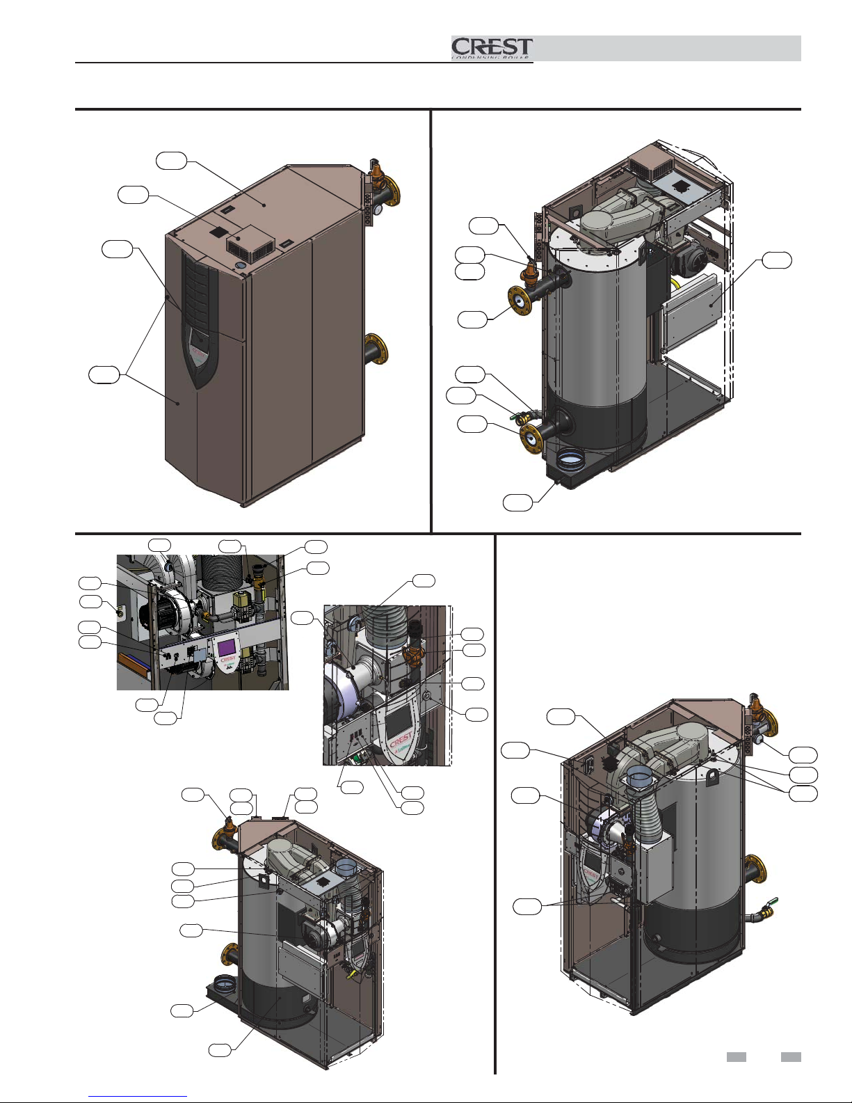
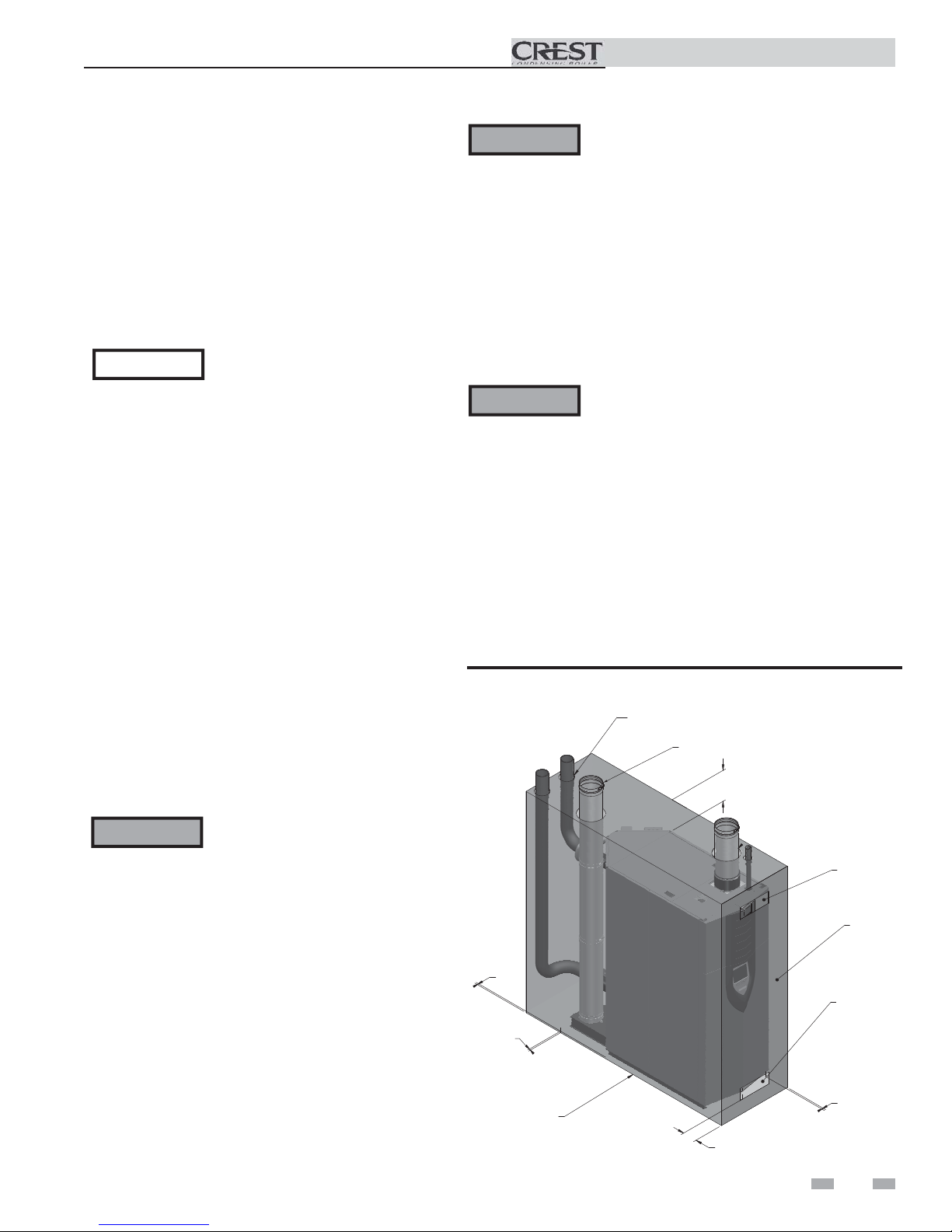
The Crest - How it works... (continued)
Models 1.5 - 5.0
2
39
11
19
7
36
Installation & Operation Manual
29
10
1
Front View
34
19
30
31
MODELS 4.0 - 5.0
28
18
40
29
23
21
22
IMG00318
34
25
26
15
16
28
5
Rear View
18
MODELS 1.5 - 3.5
30
31
6
35
15
16
23
19
9
37
3
33
12
34
13
20
12
27
4
14
32
Left Side (inside unit)
17
Right Side (inside unit)
5
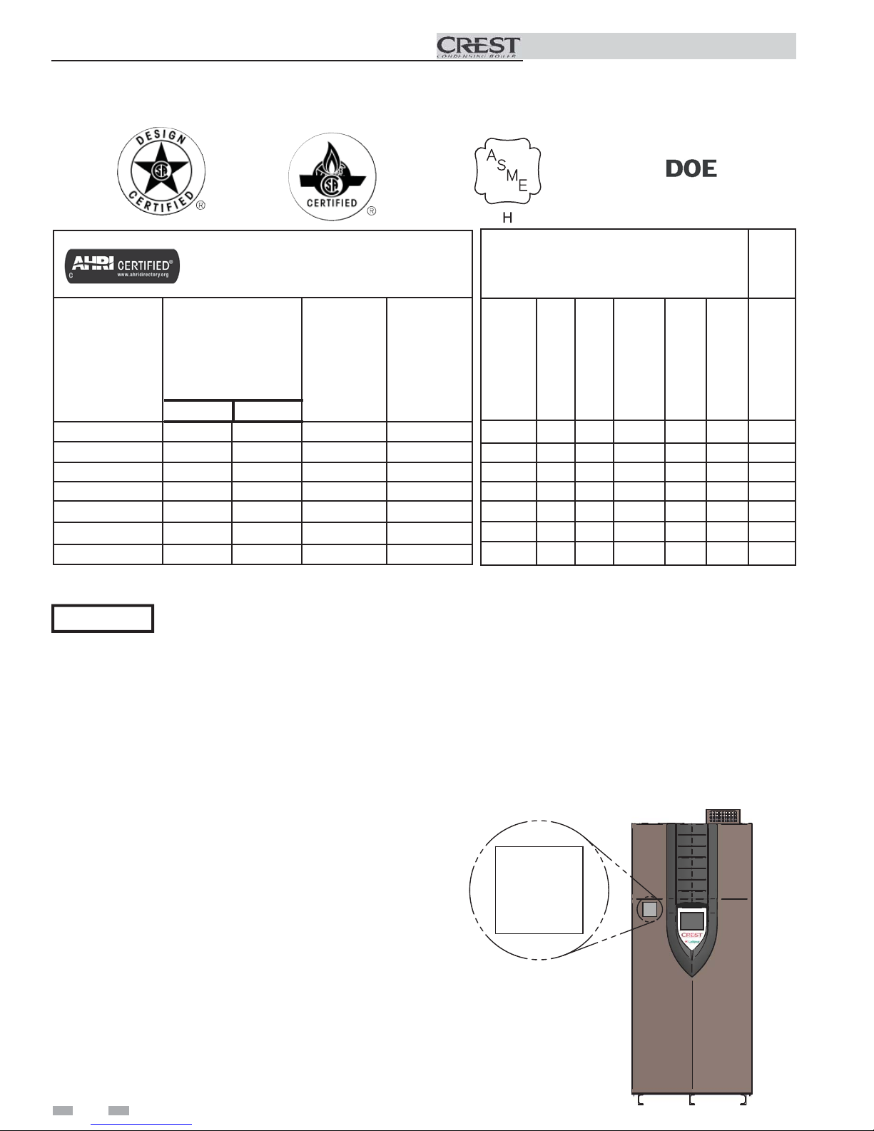
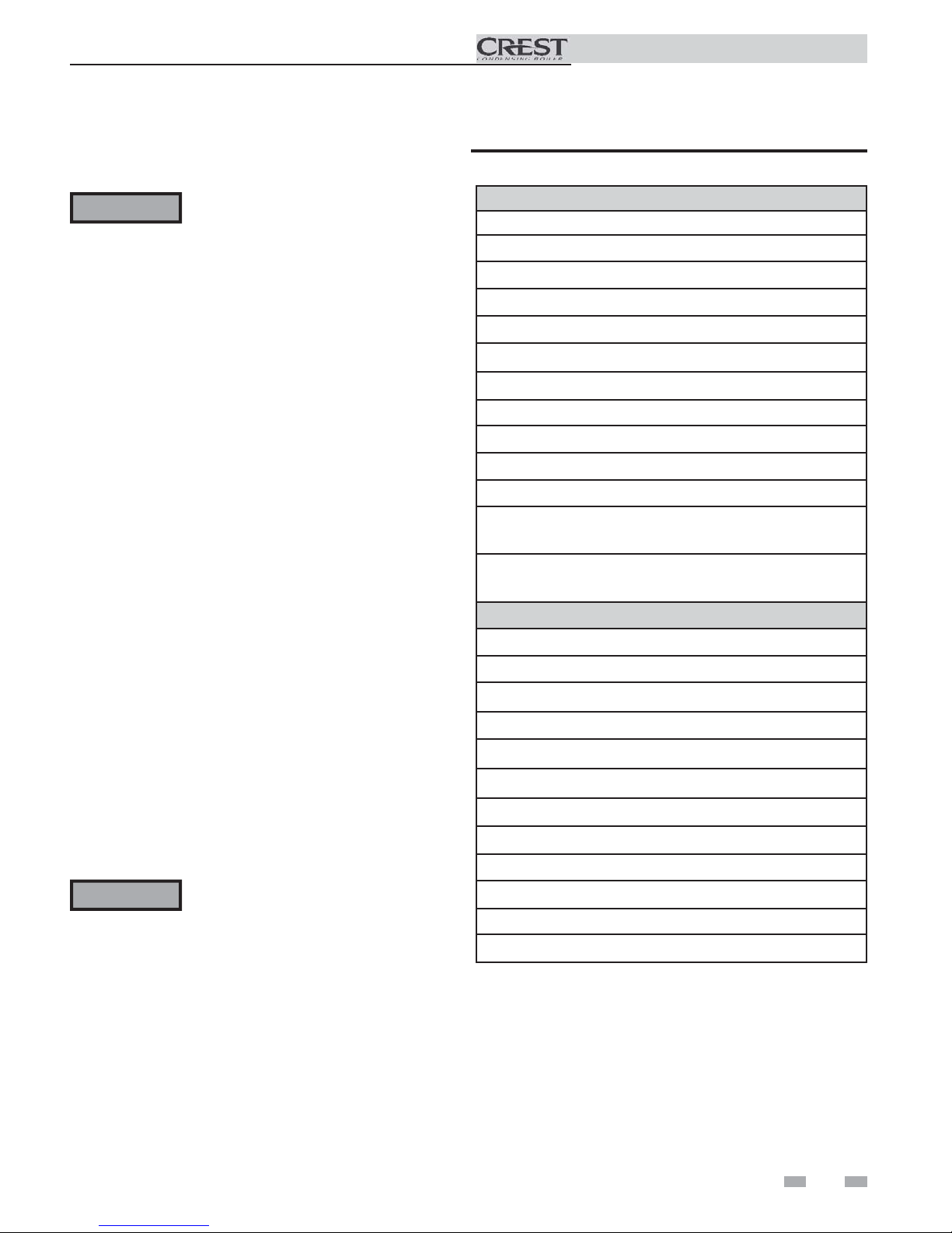
Ratings
Installation & Operation Manual
Crest
AHRI Rating
Model Number
Note: Change “N” to
“L” for L.P. gas models.
Min Max
FB(N,L)1500 60 1500 1380 1200
FB(N,L)2000 80 2000 1840 1600
FB(N,L)2500 125 2500 2300 2000
FB(N,L)3000 150 3000 2760 2400
FB(N,L)3500 200* 3500 3220 2800
FB(N,L)4000 335 4000 3720 4043
FB(N,L)5000 500 5000 4650 3235
Input
MBH
(Notes 4 - 8)
*For LP models the minimum input is 420 MBH.
NOTICE
Maximum allowed working pressure is located on the rating plate.
Notes:
1. The ratings are based on standard test procedures
prescribed by the United States Department of Energy.
2. Net AHRI ratings are based on net installed radiation of
sufficient quantity for the requirements of the building
and nothing need be added for normal piping and pickup.
Ratings are based on a piping and pickup allowance of
1.15.
3. Crest boilers require special gas venting. Use only
the vent materials and methods specified in the Crest
Installation and Operation Manual.
4. Standard Crest boilers are equipped to operate from sea
level to 4,500 feet only with no adjustments.
5. High altitude Crest Models 1.5, 2.0, 2.5, 3.0 and 3.5
boilers are equipped to operate from 3,000 to 12,000
feet and high altitude Crest Models 4.0 and 5.0 boilers
are equipped to operate from 3,000 to 5,500 feet. High
altitude models are manufactured with different control
parameters for high altitude operation, but the sequence
of operation given in this manual remains the same as
the standard boilers. A high altitude label (as shown in
FIG A.) is also affi xed to the unit.
6. Standard Crest boilers will de-rate by 2.2% for each 1,000
feet above sea level up to 4,500 feet when combustion
calibration is performed and CO2’s are adjusted to the
recommended levels.
Gross
Output
MBH
(Note 1)
Other Specifications
Net
AHRI
Ratings
Water,
MBH
(Note 2)
Appliance
Water
Content
Gallons
132 4" 4" 1 1/2" 8" 8" 3055
161 4" 4" 2" 8" 9" 3650
181 4" 4" 2" 10" 10" 4125
215 4" 4" 2" 10" 10" 4750
291 4" 4" 2 1/2" 12" 12" 6500
380 4" 4" 2 1/2" 14" 14" 8000
Pipe
Pipe
Size
Inlet
Gas Inlet
Size
Size
Outlet
96 4" 4" 1 1/2" 7" 7" 2500
7. High altitude Crest Models 1.5, 2.0, 2.5, 3.0 and 3.5 will
de-rate by 1.4% for each 1,000 feet above sea level up to 5,500
feet and 1.8% for each 1,000 feet above 5,500 feet.
8. High altitude Crest Models 4.0 and 5.0 will not de-rate up to
5,500 feet.
9. For Crest Models 4.0 and 5.0, installations above 5,500 feet
contact the factory.
10. Ratings have been confi rmed by the Hydronics Section of
AHRI.
UNIT EQUIPPED FOR
HIGH ALTITUDE
3,000 FT. TO 12,000 FT.
Air
Size
Vent
Size
(Note 3)
Weight
w/Water
(lbs.)
6
Figure A High Altitude Label Location
1 Determine boiler location
Installation must comply with:
• Local, state, provincial, and national codes, laws,
regulations, and ordinances.
• National Fuel Gas Code, NFPA 54 / ANSI Z223.1 –
latest edition.
• Standard for Controls and Safety Devices for
Automatically Fired Boilers, ANSI/ASME CSD-1 latest edition, when required.
• National Electrical Code, NFPA 70 - latest edition.
• For Canada only: CSA B149.1 Installation Code,
CSA C22.1 Canadian Electrical Code Part 1 and any
local codes.
NOTICE
Before locating the boiler, check:
1. Check for nearby connection to:
• System water piping
• Venting connections
• Gas supply piping
• Electrical power
2. Locate the appliance so that if water connections
should leak, water damage will not occur. When
such locations cannot be avoided, it is
recommended that a suitable drain pan, adequately
drained, be installed under the appliance. The
pan must not restrict combustion air flow. Under no
circumstances is the manufacturer to be held
responsible for water damage in connection with
this appliance, or any of its components.
3. Check area around the boiler. Remove any
combustible materials, gasoline and other
flammable liquids.
WARNING
4. The Crest must be installed so that gas control
system components are protected from dripping or
spraying water or rain during operation or service.
5. If a new boiler will replace an existing boiler, check
for and correct system problems, such as:
• System leaks causing oxygen corrosion or heat
exchanger cracks from hard water deposits.
• Incorrectly-sized expansion tank.
• Lack of freeze protection in boiler water causing
system and boiler to freeze and leak.
6. The appliance must be installed on a level floor,
both front to back and side to side, for proper
condensate drainage.
7. If the optional neutralizing kit is to be used, elevate
the boiler at least 3" above the floor.
The Crest gas manifold and
controls met safe lighting and other
performance criteria when the boiler
underwent tests specified in ANSI
Z21.13/CSA 4.9 – latest edition.
Failure to keep boiler area clear
and free of combustible materials,
gasoline, and other flammable
liquids and vapors can result in
severe personal injury, death, or
substantial property damage.
Installation & Operation Manual
WARNING
WARNING
Provide clearances:
Clearances from combustible materials
- Hot water pipes ........................................................ 1/4"
- Sides .......................................................................... 0"
- Rear ........................................................................... 0"
- Front ......................................................................... 0"
- Top ........................................................................... 0"
- Floor ....................................................... Combustible
- Vent pipe - Follow special vent system manufacturer’s instructions
Figure 1-1 Clearances
0"
LEFT
0"
REAR
FLOOR: COMBUSTIBLE
This appliance is certified as an indoor appliance.
Do not install the appliance outdoors or locate
where the appliance will be exposed to freezing
temperatures or to temperatures that exceed 100°F
(37.8°C).
Do not install the appliance where the relative
humidity may exceed 93%. Do not install the
appliance where condensation may form on
the inside or outside of the appliance, or where
condensation may fall onto the appliance.
Failure to install the appliance indoors could result
in severe personal injury, death, or substantial
property damage.
This appliance requires a special venting system.
Use only the vent materials specified in this
manual. Failure to follow all instructions can
result in flue gas spillage and carbon monoxide
emissions, causing severe personal injury or death.
1" (25 MM) MINIMUM CLEAR ANCE
AROUND HOT WATER PIPES
VENT PIPE: FOLLOW SPECIAL VENT SYSTEM
MANUFACTURER'S INSTRUCTIONS
0"
TOP
VENTILATING*
AIR OPENING
CLOSED DOOR
VENTILATING*
AIR OPENING
0"
RIGHT
0"
FRONT
IMG00841
7
1 Determine boiler location
Installation & Operation Manual
NOTICE
Recommended clearances for service access
- Sides .......................................................................... 24"
- Rear ........................................................................... 24"
- Front ......................................................................... 30"
- Top ........................................................................... 24"
Maintain minimum specified clearances for adequate
operation. All installations must allow sufficient space for
servicing the vent connections, water pipe connections, piping
and other auxiliary equipment, as well as the appliance. The
clearance labels on each appliance note the same service and
combustible clearance requirements as shown in this manual.
Multiple boilers may be installed side by side with no clearance
between adjacent boilers because this boiler is approved for
zero clearance from combustible surfaces; however, service
access will be limited from the sides.
Consult the Venting section of this manual for specific
installation instructions for the appropriate type of venting
system that you will be using.
If you do not provide the recommended
service clearances shown, it may not be
possible to service the boiler without
removing it from the space.
Provide air openings to room:
The Crest alone in boiler room
1. No air ventilation openings into the boiler room are
needed when clearances around the Crest are at least
equal to the SERVICE clearances shown in FIG. 1-1.
For spaces that do NOT supply this clearance, provide
two openings as shown in FIG. 1-1. Each opening must
provide one square inch free area per 1,000 Btu/hr of
boiler input.
2. Combustion air openings are required when using the
Room Air Option on page 23 of this manual.
The Crest in same space with other gas or oil-fired
appliances
1. Follow the National Fuel Gas Code (U.S.) or CSA B149.1
(Canada) to size/verify size of the combustion/ventilation
air openings into the space.
WARNING
2. Size openings only on the basis of the other appliances in
the space. No additional air opening free area is needed
for the Crest when it takes its combustion air from
outside (direct vent installation).
The space must be provided with
combustion/ventilation air openings
correctly sized for all other appliances
located in the same space as the Crest.
Failure to comply with the above warnings
could result in severe personal injury,
death, or substantial property damage.
8
Flooring and foundation
Flooring
The Crest is approved for installation on combustible flooring,
but must never be installed on carpeting.
WARNING
If flooding is possible, elevate the boiler sufficiently to prevent
water from reaching the boiler.
WARNING
Do not install the boiler on carpeting even if
foundation is used. Fire can result, causing
severe personal injury, death, or substantial
property damage.
Assure that the floor and structure is
sufficient to support the installed weight
of the boiler, including the water content
in the heat exchanger. If not, structural
building failure will result, causing severe
personal injury, death, or substantial
property damage.
Vent and air piping
The Crest requires a special gas vent system, designed for
pressurized venting.
The boiler is to be used for either direct vent installation or
for installation using indoor combustion air. When room air
is considered, see page 23 of this manual. Note prevention of
combustion air contamination below when considering vent/
air termination.
Vent and air must terminate near one another and may be
vented vertically through the roof or out a side wall, unless
otherwise specified. You may use any of the vent/air piping
methods covered in this manual. Do not attempt to install
the Crest using any other means.
Be sure to locate the boiler such that the vent and air piping
can be routed through the building and properly terminated.
The vent/air piping lengths, routing and termination method
must all comply with the methods and limits given in this
manual.
Prevent combustion air contamination
Install air inlet piping for the Crest as described in this
manual. Do not terminate vent/air in locations that can
allow contamination of combustion air. Refer to Table 1A,
page 9 for products and areas which may cause contaminated
combustion air.
WARNING
Ensure that the combustion air will not
contain any of the contaminants in Table
1A, page 9. Contaminated combustion
air will damage the boiler, resulting in
possible severe personal injury, death
or substantial property damage. Do not
pipe combustion air near a swimming
pool, for example. Also, avoid areas
subject to exhaust fumes from laundry
facilities. These areas will always contain
contaminants.
1 Determine boiler location (continued)
When using an existing vent system to
install a new boiler:
Table 1A Corrosive Contaminants and Sources
Installation & Operation Manual
WARNING
Check the following venting components before installing:
• Material - For materials listed for use with this appliance,
see Section 2 - General Venting, Table 2A. For stainless
steel venting, an adapter of the same manufacturer
(Table 2B) may be used at the flue collar connection.
• Size - To ensure proper pipe size is in place, see Table 2C.
Check to see that this size is used throughout the vent
system.
• Manufacturer - Only use the listed manufacturers and
their type product listed in Table 2A for CAT IV positive
pressure venting with flue producing condensate.
• Supports - Non-combustible supports must be in place
allowing a minimum 1/4" rise per foot. The supports
should adequately prevent sagging and vertical slippage,
by distributing the vent system weight. For additional
information, consult the vent manufacturer’s
instructions for installation.
• Terminations - Carefully review Sections 2 through 4 to
ensure requirements for the location of the vent and air
terminations are met and orientation of these fit the
appropriate image from the Sidewall or Vertical
options listed in the General Venting Section.
• Seal - With prior requirements met, the system should be
tested to the procedure listed in parts (c) through (f) of
the Removal of an Existing Boiler Section on page 10.
With stainless steel vent, seal and connect all pipe and
components as specified by the vent manufacturer used.
WARNING
Failure to follow all instructions can result
in flue gas spillage and carbon monoxide
emissions, causing severe personal injury
or death.
If any of these conditions are not met,
the existing system must be updated or
replaced for that concern. Failure to
follow all instructions can result in flue gas
spillage and carbon monoxide emissions,
causing severe personal injury or death.
Products to avoid:
Spray cans containing chloro/fluorocarbons
Permanent wave solutions
Chlorinated waxes/cleaners
Chlorine-based swimming pool chemicals
Calcium chloride used for thawing
Sodium chloride used for water softening
Refrigerant leaks
Paint or varnish removers
Hydrochloric acid/muriatic acid
Cements and glues
Antistatic fabric softeners used in clothes dryers
Chlorine-type bleaches, detergents, and cleaning solvents
found in household laundry rooms
Adhesives used to fasten building products and other similar
products
Areas likely to have contaminants
Dry cleaning/laundry areas and establishments
Swimming pools
Metal fabrication plants
Beauty shops
Refrigeration repair shops
Photo processing plants
Auto body shops
Plastic manufacturing plants
Furniture refinishing areas and establishments
New building construction
Remodeling areas
Garages with workshops
9
1 Determine boiler location
When removing a boiler from existing
common vent system:
Installation & Operation Manual
DANGER
WARNING
At the time of removal of an existing boiler, the following
steps shall be followed with each appliance remaining
connected to the common venting system placed in
operation, while the other appliances remaining connected
to the common venting system are not in operation.
a. Seal any unused openings in the common venting
system.
b. Visually inspect the venting system for proper size and
horizontal pitch and determine there is no blockage or
restriction, leakage, corrosion, or other deficiencies,
which could cause an unsafe condition.
c. Test vent system – Insofar as is practical, close all
building doors and windows and all doors between
the space in which the appliances remaining connected
to the common venting system are located and other
spaces of the building. Turn on clothes dryers and
any appliance not connected to the common venting
system. Turn on any exhaust fans, such as range
hoods and bathroom exhausts, so they will operate at
maximum speed. Do not operate a summer exhaust
fan. Close fireplace dampers.
Do not install the Crest into a common
vent with any other appliance except
as noted in Section 2 on page 18.
This will cause flue gas spillage or
appliance malfunction, resulting in
possible severe personal injury, death,
or substantial property damage.
Failure to follow all instructions can
result in flue gas spillage and carbon
monoxide emissions, causing severe
personal injury or death.
d. Place in operation the appliance being inspected.
Follow the lighting instructions. Adjust thermostat so
appliance will operate continuously.
e. Test for spillage at the draft hood relief opening after
5 minutes of main burner operation. Use the flame of
a match or candle, or smoke from a cigarette, cigar, or
pipe.
f. After it has been determined that each appliance
remaining connected to the common venting system
properly vents when tested as outlined herein, return
doors, windows, exhaust fans, fireplace dampers, and
any other gas-burning appliance to their previous
conditions of use.
g. Any improper operation of the common venting
system should be corrected so the installation conforms
with the National Fuel Gas Code, ANSI Z223.1/NFPA
54 and/or CAN/CSA B149.1, Natural Gas and Propane
Installation Code. When re-sizing any portion of the
common venting system, the common venting system
should be resized to approach the minimum size as
determined using the appropriate tables in Part 11 of
the National Fuel Gas Code, ANSI Z223.1/NFPA 54
and/or CAN/CSA B149.1, Natural Gas and Propane
Installation Code.
10
1 Determine boiler location (continued)
Installation & Operation Manual
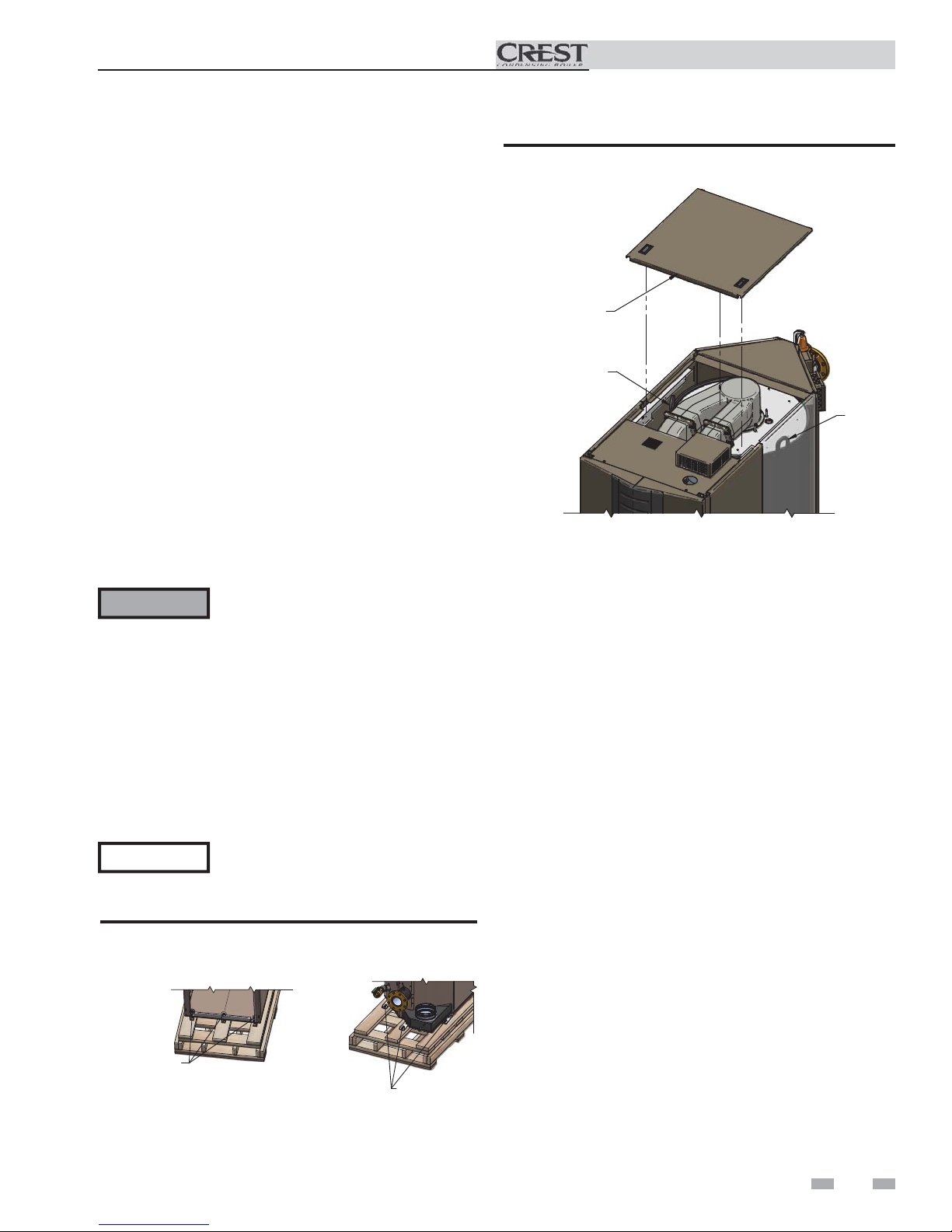
Remove boiler from wood pallet
1. After removing the outer shipping crate and plastic
from the boiler, remove the parts package (packaged parts
inside the controls compartment of the boiler inside the
lower front access panel).
2. To remove the boiler from the pallet:
a. Remove the three (3) shipping bolts located inside
the controls compartment securing the boiler to the
front of the pallet (see FIG. 1-2).
b. Remove the three (3) shipping bolts that fasten the
tie-down brackets securing the legs to the rear of the
pallet (FIG. 1-2).
c. The boiler can now be removed from the pallet
using a lift truck lifting from the front or rear of
the boiler. If lifting from the front, the lift truck
forks must extend at least half way under the boiler
heat exchanger to assure proper lifting technique
with no damage to the boiler.
WARNING
Failure to assure the truck forks are
long enough to extend at least halfway
under the boiler heat exchanger will
result in the boiler tipping off the lift
truck, and potentially falling. This will
result in severe personal injury, death, or
substantial property damage.
Figure 1-3 Boiler Removed from Shipping Pallet
REMOVE MIDDLE
TOP COVER
LIFTING
LUGS
LIFTING
LUGS
d. If lifting by crane is desired, remove the top access
panels to gain access to the lifting lugs located on the
boiler (see FIG. 1-3). It is also recommended that the
upper and lower front panels along with both front
side panels be removed (no tools required).
NOTICE
Do not drop the boiler or bump the jacket
on the floor or pallet. Damage to the
boiler can result.
Figure 1-2 Boiler Mounted on Shipping Pallet
BOLT, WASHERS
& LOCKNUT (3X)
FRONT
REAR
LAG BOLTS & TABS
(3X)
11
1 Determine boiler location
Combustion and ventilation air
requirements for appliances drawing air
from the equipment room
Provisions for combustion and ventilation air must be in
accordance with Air for Combustion and Ventilation, of the
latest edition of the National Fuel Gas Code, NFPA 54 / ANSI
Z223.1, in Canada, the latest edition of CGA Standard B149
Installation Code for Gas Burning Appliances and Equipment,
or applicable provisions of the local building codes.
The equipment room MUST be provided with properly sized
openings and/or be of sufficient volume to assure adequate
combustion air and proper ventilation for all gas fired appliances
in the equipment room to assure adequate combustion air and
proper ventilation.
The requirements shown are for the appliance only; additional
gas fired appliances in the equipment room will require an
increase in the net free area and/or volume to supply adequate
combustion air for all appliances.
Figure 1-5_Combustion Air Through Ducts
2. If combustion and ventilation air is taken from the
outdoors using a duct to deliver the air to the
equipment room, each of the two openings should be
sized based on a minimum free area of one square inch
per 2000 Btu/hr (11 cm2 per kW) of input (see FIG. 1-5).
Installation & Operation Manual
No combustion air openings are needed when the appliance is
installed in a space with a volume NO LESS than 50 cubic feet
per 1,000 Btu/hr of all installed gas fired appliances and the
building MUST NOT be of “Tight Construction”3.
A combination of indoor and outdoor combustion air may
be utilized by applying a ratio of available volume to required
volume times the required outdoor air opening(s) size(s). This
must be done in accordance with the National Fuel Gas Code,
NFPA 54 / ANSI Z223.1.
Figure 1-6_Combustion Air from Interior Space
3. If air is taken from another interior space combined with
the equipment room:
(a) Two spaces on same story: Each of the two openings
specified above should have a net free area of one square
inch for each 1000 Btu/hr (22 cm2 per kW) of input, but
not less than 100 square inches (645 cm2) (see FIG. 1-6).
(b) Two spaces on different stories: One or more openings
should have a net free area of two square inches per 1000
Btu/hr (44 cm2 per kW).
Figure 1-4_Combustion Air Direct from Outside
1. If air is taken directly from outside the building
with no duct, provide two permanent openings to
the equipment room each with a net free area of one square
inch per 4000 Btu/hr input (5.5 cm2 per kW) (see FIG. 1-4).
12
Figure 1-7_Combustion Air from Outside - Single Opening
1 Determine boiler location (continued)
Installation & Operation Manual
4. If a single combustion air opening is provided to bring
combustion air in directly from the outdoors, the
opening must be sized based on a minimum free area
of one square inch per 3000 Btu/hr (7 cm2 per kW). This
opening must be located within 12” (30 cm) of the top of
the enclosure (see FIG. 1-7).
Combustion air requirements are based on the latest edition
of the National Fuel Gas Code, NFPA 54 / ANSI Z223.1; in
Canada refer to the latest edition of CGA Standard CAN/CSA
B149.1. Check all local code requirements for combustion air.
All dimensions based on net free area in square inches. Metal
louvers or screens reduce the free area of a combustion air
opening a minimum of approximately 25%. Check with
louver manufacturers for exact net free area of louvers.
Where two openings are provided, one must be within 12"
(30 cm) of the ceiling and one must be within 12" (30 cm) of
the floor of the equipment room. Each opening must have a
net free area as specified in Table 1B. Single openings shall
commence within 12" (30 cm) of the ceiling. The minimum
dimension of air openings shall not be less than 3" (80 mm).
CAUTION
Under no circumstances should the
equipment room ever be under negative
pressure. Particular care should be taken
where exhaust fans, attic fans, clothes dryers,
compressors, air handling units, etc., may
take away air from the unit.
The combustion air supply must be completely free of any
flammable vapors that may ignite or chemical fumes which may
be corrosive to the appliance. Common corrosive chemical
fumes which must be avoided are fluorocarbons and other
halogenated compounds, most commonly present as refrigerants
or solvents, such as Freon, trichlorethylene, perchlorethylene,
chlorine, etc. These chemicals, when burned, form acids which
quickly attack the stainless steel heat exchanger, headers, flue
collectors, and the vent system.
The result is improper combustion and a non-warrantable,
premature appliance failure.
EXHAUST FANS: Any fan or equipment which exhausts air
from the equipment room may deplete the combustion air
supply and/or cause a downdraft in the venting system. Spillage
of flue products from the venting system into an occupied
living space can cause a very hazardous condition that must be
corrected immediately.
FIG. 1-4 FIG. 1-5 FIG. 1-6 FIG. 1-7
*Outside Air from
Model
Number
FB 1500
FB 2000
FB 2500
FB 3000
FB 3500
FB 4000
FB 5000
2 Openings Directly from
2
1
Bottom
Opening, in
(cm2)
375
(2420)
500
(3226)
625
(4033)
750
(4839)
875
(5646)
1000
(6450)
1250
(8062)
Outdoors
Top
Opening, in
(cm2)
375
(2420)
500
(3226)
625
(4033)
750
(4839)
875
(5646)
1000
(6450)
1250
(8062)
The above requirements are for the appliance only; additional gas fired appliances in the equipment room will require an increase
in the net free area and/or volume to supply adequate combustion air for all appliances.
No combustion air openings are needed when the appliance is installed in a space with a volume NO LESS than 50 cubic feet per
1,000 Btu/hr of all installed gas fired appliances. Buildings MUST NOT be of *“Tight Construction”3.
1
Outside air openings shall directly communicate with the outdoors.
2
Combined interior space must be 50 cubic feet per 1,000 Btu/hr input. Buildings MUST NOT be of *“Tight Construction”.
3
”Tight Construction” is defined as a building with less than 0.40 ACH (air changes per hour). For buildings of “Tight
Construction”, provide air openings into the building from outside.
TABLE - 1B
MINIMUM RECOMMENDED COMBUSTION
AIR SUPPLY TO EQUIPMENT ROOM
*Outside Air from
2 Ducts Delivered from
Outdoors
2
Top
Opening, in
(cm2)
750
(4839)
1000
(6452)
1250
(8065)
1500
(9678)
1750
(11291)
2000
(12900)
2000
(12900)
2
1
Bottom
Opening, in
(cm2)
750
(4839)
1000
(6452)
1250
(8065)
1500
(9678)
1750
(11291)
2000
(12900)
2000
(12900)
2 Ducts Delivered from Interior Space
2
Top
Opening, in
(cm2)
1500
(9678)
2000
(12904)
2500
(16129)
3000
(19355)
3500
(22581)
4000
(25800)
5000
(32250)
Inside Air from
Same Story
2
Bottom
Opening, in
(cm2)
1500
(9678)
2000
(12904)
2500
(16129)
3000
(19355)
3500
(22581)
4000
(25800)
5000
(32250)
Different
2
Opening, in
Stories
Total
(cm2)
3000
(19355)
4000
(25807)
5000
(32258)
6000
(38710)
7000
(45162)
8000
(51600)
10000
(64500)
2
*Outside Air from
1 Opening Directly
from Outdoors, in
(cm2)
2
500
(3226)
667
(4304)
833
(5381)
1000
(6452)
1167
(7530)
1333
(8600)
1667
(10750)
2
1
13
2 General venting
Installation & Operation Manual
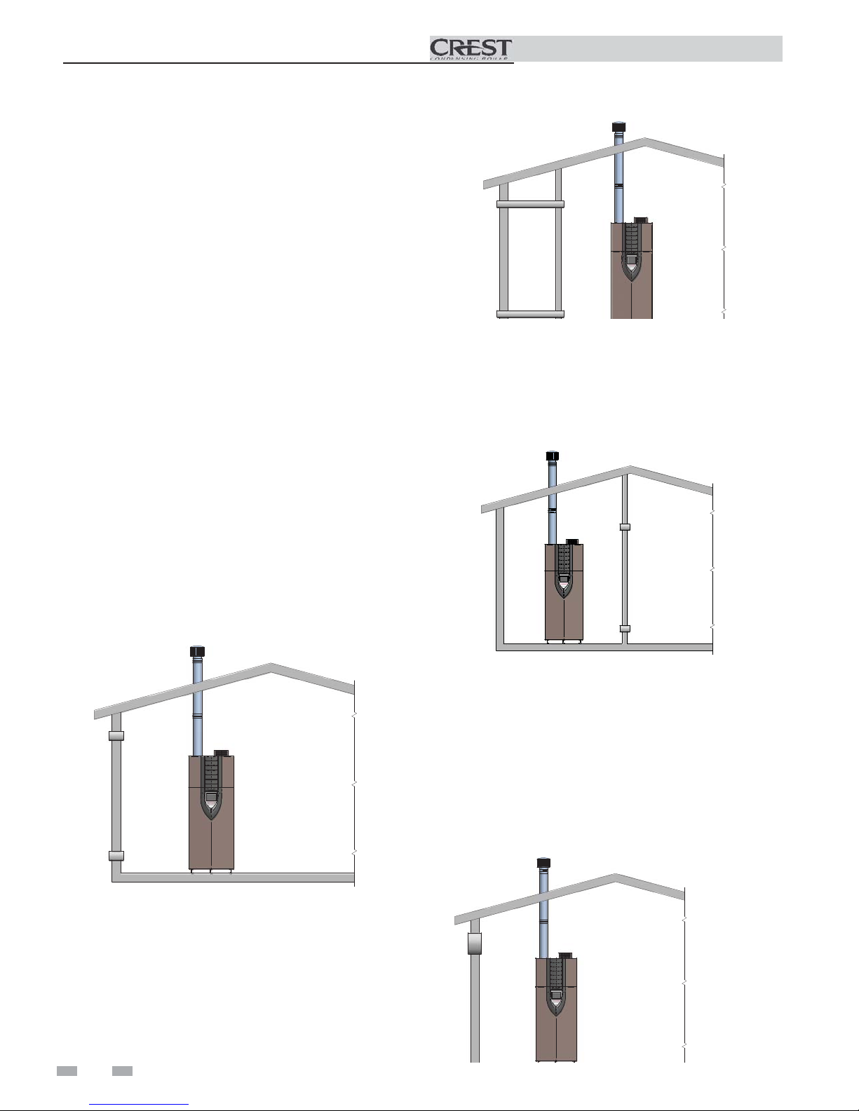
Direct venting
Sidewall
Vertical Vent, Sidewall Air
Optional room air
Vertical
Sidewall
14
Vertical
2 General venting (continued)
Install vent and combustion air piping
Installation & Operation Manual
DANGER
The Crest must be vented and supplied
with combustion and ventilation air as
described in this section. Ensure the vent
and air piping and the combustion air
supply comply with these instructions
regarding vent system, air system, and
combustion air quality. See also Section
1 of this manual.
Inspect finished vent and air piping
thoroughly to ensure all are airtight and
comply with the instructions provided
and with all requirements of applicable
codes.
Failure to provide a properly installed
vent and air system will cause severe
personal injury or death.
Air inlet pipe materials:
The air inlet pipe(s) must be sealed. Choose acceptable
combustion air inlet pipe materials from the following list:
ABS, PVC, or CPVC
Dryer Vent or Sealed Flexible Duct (not recommended
for rooftop air inlet)
Galvanized steel vent pipe with joints and seams sealed
as specified in this section.
Type “B” double-wall vent with joints and seams sealed
as specified in this section.
AL29-4C, stainless steel material to be sealed to
specification of its manufacturer.
Sealing of Type “B” double-wall vent material or galvanized
vent pipe material used for air inlet piping on a sidewall or
vertical rooftop Combustion Air Supply System:
a. Seal all joints and seams of the air inlet pipe using either
Aluminum Foil Duct Tape meeting UL Standard 723 or
181A-P or a high quality UL Listed silicone sealant such
as those manufactured by Dow Corning or General
Electric.
b. Do not install seams of vent pipe on the bottom of
horizontal runs.
c. Secure all joints with a minimum of three sheet metal
screws or pop rivets. Apply Aluminum Foil Duct Tape or
silicone sealant to all screws or rivets installed in the vent
pipe.
d. Ensure that the air inlet pipes are properly supported.
The PVC, CPVC, or ABS air inlet pipe should be cleaned and
sealed with the pipe manufacturer’s recommended solvents
and standard commercial pipe cement for the material used.
The ABS, PVC, CPVC, Dryer Vent or Flex Duct air inlet pipe
should use a silicone sealant to ensure a proper seal at the
appliance connection and the air inlet cap connection. Dryer
vent or flex duct should use a screw type clamp to seal the
vent to the appliance air inlet and the air inlet cap. Proper
sealing of the air inlet pipe ensures that combustion air will be
free of contaminants and supplied in proper volume.
*Plastic pipe may require an adapter (not provided) to
transition between the air inlet connection on the appliance
and the plastic air inlet pipe.
WARNING
NOTICE
Using vent or air intake materials other
than those specified, failure to properly
seal all seams and joints or failure to follow
vent pipe manufacturer’s instructions can
result in personal injury, death or property
damage. Mixing of venting materials will
void the warranty and certification of the
appliance.
The use of double-wall vent or insulated
material for the combustion air inlet
pipe is recommended in cold climates
to prevent the condensation of airborne
moisture in the incoming combustion air.
15
2 General venting
Installation & Operation Manual
When a sidewall or vertical rooftop combustion air supply
system is disconnected for any reason, the air inlet pipe must
be resealed to ensure that combustion air will be free of
contaminants and supplied in proper volume.
DANGER
Failure to properly seal all joints and seams
as required in the air inlet piping may
result in flue gas recirculation, spillage
of flue products and carbon monoxide
emissions causing severe personal injury
or death.
Vent and air piping
This product has been approved for use with stainless steel
vent systems.
WARNING
NOTICE
NOTICE
Use only the materials, vent systems, and
terminations listed in Table 2A. DO
NOT mix vent systems of different types
or manufacturers, unless listed in this
manual. Failure to comply could result
in severe personal injury, death, or
substantial property damage.
Installations must comply with applicable
national, state, and local codes. Stainless
steel vent systems must be listed as a
UL-1738 approved system for the United
States and a ULC-S636 approved system
for Canada.
Installation of a stainless steel vent system
should adhere to the stainless steel vent
manufacturer’s installation instructions
supplied with the vent system.
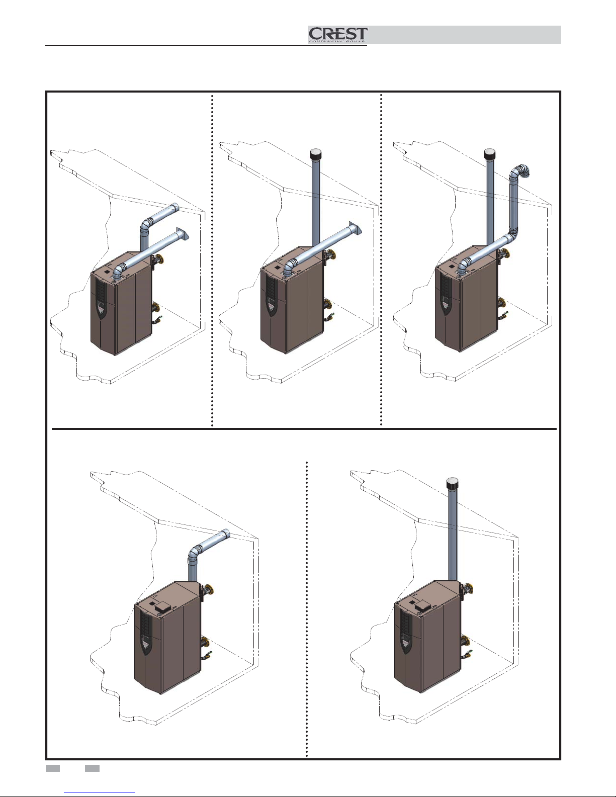
Air intake/vent connections
1. Combustion Air Intake Connector (FIG. 2-1) - Used to
provide combustion air directly to the unit from outdoors.
A fitting is provided with the unit for final connection.
Combustion air piping must be supported per guidelines
listed in the National Mechanical Code, Section 305, Table
305.4 or as local codes dictate.
2. Vent Connector (FIG. 2-1) - Used to provide a
passageway for conveying combustion gases to the
outside. A transition fitting is provided on the unit for
final connection. Vent piping must be supported per the
National Building Code, Section 305, Table 305.4 or as
local codes dictate.
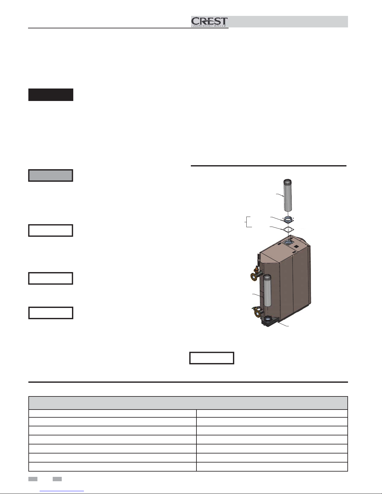
Figure 2-1 Combustion Air Adapter
AIR PIPE
(FIELD SUPPLIED)
SHIPPED LOOSE
WITH THE BOILER
VENT PIPE
(FIELD SUPPLIED)
ADAPTER
GASKET
NOTICE
The Crest is supplied with an integral
FasNSeal vent connector (FIG. 2-1). The
installer must use a specific vent starter
adapter supplied by the vent manufacturer
to adapt to different vent systems.
Table 2A Approved Stainless Steel Vent Manufacturers
Approved Stainless Steel Vent Manufacturers
Make Model
ProTech Systems (Simpson Dura-Vent Co.) FasNSeal Vent
Z-Flex (Nova Flex Group) Z-Vent
Heat Fab (Selkirk Corporation) Saf-T Vent
Metal Fab Corr/Guard
Securities Chimneys International Secure Seal SS
Schebler Chimney Systems eVent
16
CONNECTOR
The Crest uses model specific combustion air intake and vent
piping sizes as detailed in Tables 2B and 2C on page 17.
NOTICE
Increasing or decreasing combustion air
or vent piping to sizes not specified in this
manual is not authorized.
Installation & Operation Manual
2 General venting (continued)
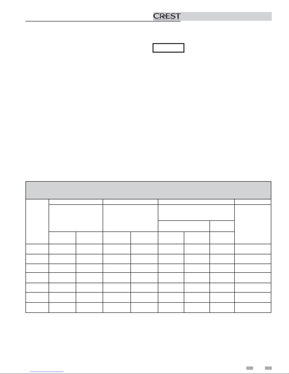
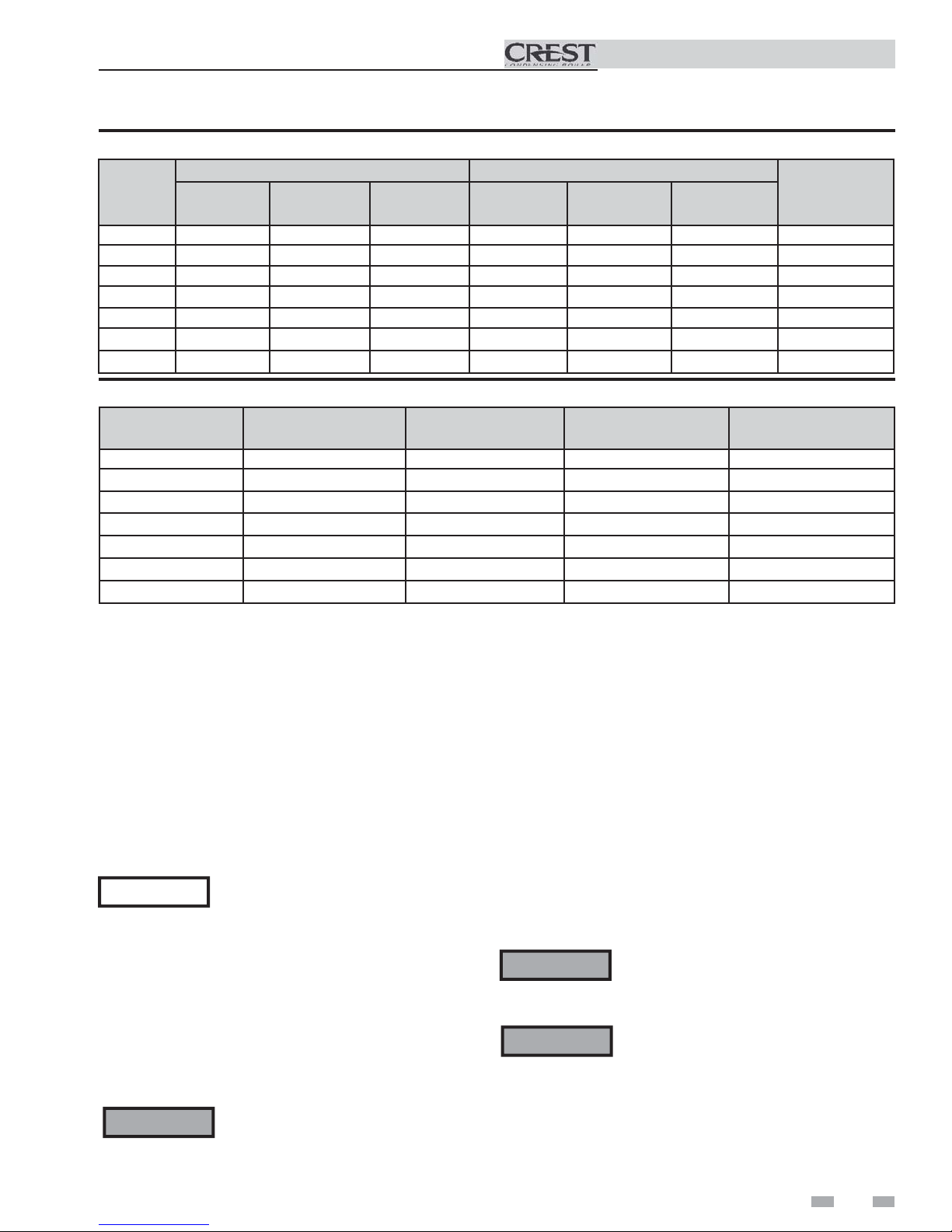
Table 2B Direct Vent Minimum / Maximum Allowable Air / Vent Lengths
AIR INLET VENT
Model
FB 1500 7" 12' 100' 7" 12' 100' 2%
FB 2000 8" 12' 100' 8" 12' 100' 2%
FB 2500 8" 12' 100' 9" 12' 100' 2%
FB 3000 10" 12' 100' 10" 12' 100' 2%
FB 3500 10" 12' 100' 10" 12' 100' 2%
FB 4000 12" 12' 100' 12" 12' 100' 0.5%
FB 5000 14" 12' 100' 14" 12' 100' 0%
Table 2C Room Air Minimum / Maximum Allowable Air / Vent Lengths
Air Intake
Diameter
Air Intake
Min. Length
Air Intake
Max. Length
Vent
Diameter
Vent
Min. Length
Vent
Max. Length
De-Rate per
25 feet of Vent
Input
Model
FB 1500 7" 12' 100' 1%
FB 2000 8" 12' 100' 1%
FB 2500 9" 12' 100' 1%
FB 3000 10" 12' 100' 1%
FB 3500 10" 12' 100' 1%
FB 4000 12" 12' 100' 0%
FB 5000 14" 12' 100' 0%
When determining equivalent combustion air and vent
length, add 5 feet (1.5m) for each 90° elbow and 3 feet (.9 m)
for each 45° elbow.
EXAMPLE: 20 feet (6 m) of pipe + (4) 90° elbows + (3) 45°
elbows = 49 equivalent feet (15 m) of piping.
Vent
Diameter
Removing from existing vent
Follow the instructions in Section 1, page 10 of this manual
when removing a boiler from an existing vent system.
Vent and air piping
Vent and air system:
NOTICE
You must also install air piping from outside to the boiler
air intake adapter. The resultant installation is direct vent
(sealed combustion).
You may use any of the vent/air piping methods covered in
this manual. Do not attempt to install the Crest using any
other means.
WARNING
Installation must comply with local
requirements and with the National Fuel
Gas Code, NFPA 54 / ANSI Z223.1 for U.S.
installations or CSA B149.1 for Canadian
installations.
DO NOT mix components from different
systems. The vent system could fail,
causing leakage of flue products into the
living space. Use only approved stainless
steel pipe and fittings.
Vent
Min. Length
Vent, air piping and termination:
The Crest vent and air piping can be installed through the roof
or through a sidewall. Follow the procedures in this manual for
the method chosen. Refer to the information in this manual to
determine acceptable vent and air piping length.
Air contamination
Pool and laundry products and common household and hobby
products often contain fluorine or chlorine compounds. When
these chemicals pass through the boiler, they can form strong
acids. The acid can eat through the boiler wall, causing serious
damage and presenting a possible threat of flue gas spillage or
boiler water leakage into the building.
Please read the information given in Table 1A, page 9,
listing contaminants and areas likely to contain them. If
contaminating chemicals will be present near the location of the
boiler combustion air inlet, have your installer pipe the boiler
combustion air and vent to another location, per this manual.
WARNING
WARNING
Vent
Max. Length
If the boiler combustion air inlet is located
in a laundry room or pool facility, for
example, these areas will always contain
hazardous contaminants.
To prevent the potential of severe personal
injury or death, check for areas and products
listed in Table 1A, page 9 before installing
the boiler or air inlet piping.
If contaminants are found, you MUST:
• Remove products permanently.
—OR—
• Relocate air inlet and vent
terminations to other areas.
Input De-Rate per
25 feet of Vent
17
2 General venting
Common venting
Installation & Operation Manual
Crest boilers may be common vented; however, the following
criteria MUST BE followed:
1. Only Crest boilers may be connected to the common
vent. DO NOT mix other manufacturer’s appliances or
other Lochinvar models.
2. Crest boilers connected to the common vent must all be
of the same size.
3. Each Crest boiler must have a Lochinvar supplied flue
damper installed (see Table 2D).
4. Only vertical direct vent, positive pressure, Category
IV or vertical/chimney vent, negative pressure, Category
II may be used when common venting Crest boilers.
Sidewall venting is not allowed.
5. Crest boilers in a common vent must be connected and
controlled with the integral Crest SMART TOUCH
Cascade.
a. The Leader may be controlled through the Crest
SMART TOUCH control through BMS (external
0 - 10V signal), ModBus or its own internally
calculated set point.
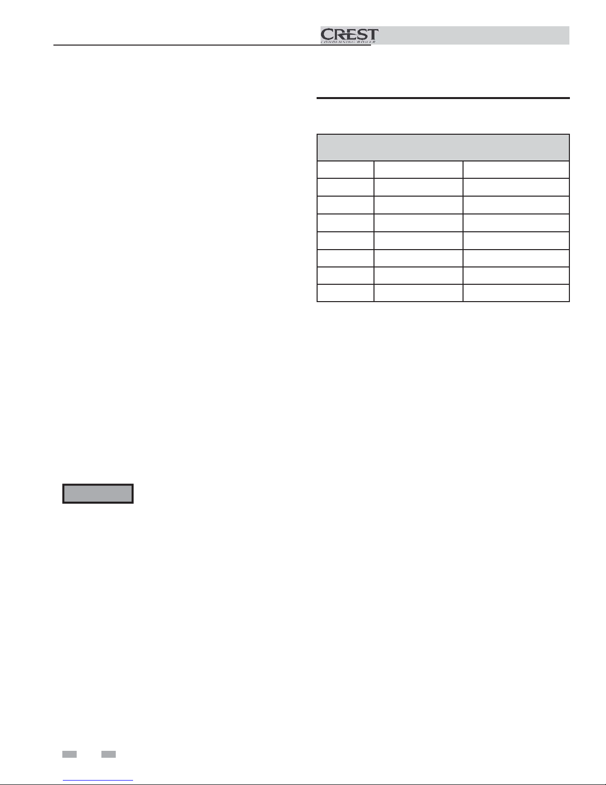
Table 2D Flue Damper Kits
Flue Damper Kits
Model Damper Size Kit Number
FB1500 7" DRH30000
FB2000 8" DRH30001
FB2500 9" DRH30002
FB3000 10" DRH30003
FB3500 10" DRH30003
FB4000 12" DRH30004
FB5000 14" DRH30005
b. The Cascade (Members) must be controlled by the
Crest Leader boiler using the Lead/Lag Cascade
option.
For approved common vent sizing, contact the factory.
WARNING
When Crest boilers are common vented,
the criteria above MUST BE followed.
Failure to follow all these requirements
will result in severe personal injury, death,
or substantial property damage.
18
3 Vertical direct venting
A
A
Vent/air termination – vertical
Installation & Operation Manual
WARNING
Follow instructions below when determining
vent location to avoid possibility of severe
personal injury, death or substantial property
damage.
WARNING
Do not connect any other appliance to the
vent pipe or multiple boilers to a common
vent pipe except as noted in Section 2 on
page 18. Failure to comply could result in
severe personal injury, death, or substantial
property damage.
NOTICE
Installation must comply with local
requirements and with the National Fuel
Gas Code, NFPA 54 / ANSI Z223.1 - latest
edition for U.S. installations or CSA B149.1
Installation Code for Canadian installations.
Determine location
Locate the vent/air terminations using the following guidelines:
1. The total length of piping for vent or air must not exceed
the limits given in the General Venting Section on page 17
of this manual.
2. The vent must terminate at least 3 feet above the highest
place in which the vent penetrates the roof and at least 2 feet
above any part of a building within 10 horizontal feet.
3. The air piping must terminate in a down-turned 180°
return pipe no further than 2 feet (.6 m) from the center of
the vent pipe. This placement avoids recirculation of flue
products into the combustion air stream.
4. The vent piping must terminate in an up-turned coupling
as shown in FIG. 3-1. The top of the coupling or the rain
cap must be at least 36" (914 mm) above the air intake. The
air inlet pipe and vent pipe can be located in any desired
position on the roof, but must always be no further than 2
feet (.6 m) apart and with the vent termination at least 36"
(914 mm) above the air intake.
WARNING
Rooftop vent and air inlet terminations
must terminate in the same pressure zone,
unless vertical vent sidewall air is set up as
shown in the General Venting - Vertical
Vent, Sidewall Air Section.
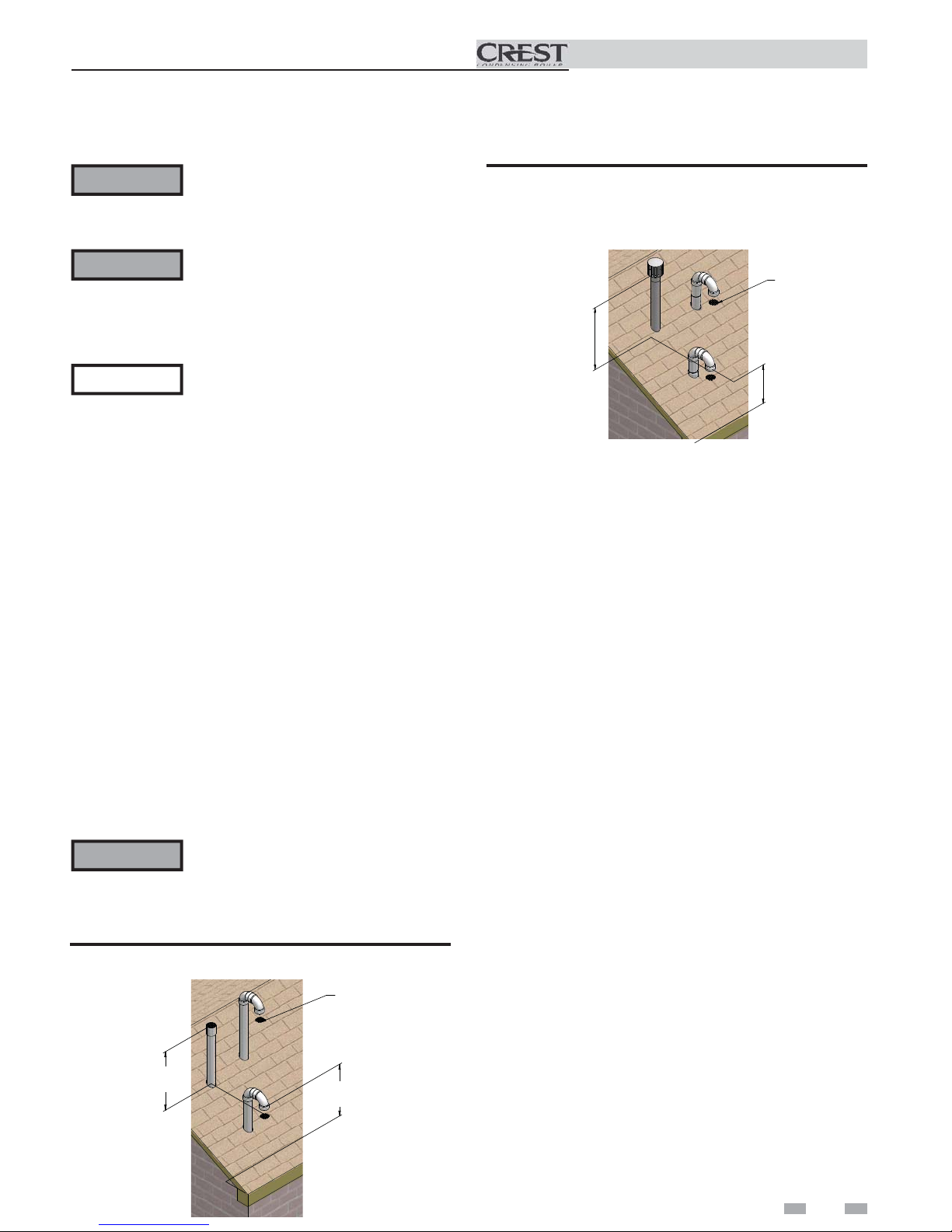
Figure 3-2 Vertical Termination of Air and Vent w/Rain
Cap
BIRD SCREEN
[TYPICAL]
VENT OUTLET
36" [914 MM] MINIMUM
BOVE AIR INLET
12" [305 MM] MINIMUM
ABOVE ROOF /
SNOW LINE
5. Locate terminations so they are not likely to be damaged
by foreign objects, such as stones or balls, or subject to
buildup of leaves or sediment.
Prepare roof penetrations
1. Air pipe penetration:
a. Cut a hole for the air pipe. Size the air pipe hole as
close as desired to the air pipe outside diameter.
2. Vent pipe penetration:
a. Cut a hole for the vent pipe. For either combustible
or noncombustible construction, size the vent pipe
hole per the vent manufacturer’s instructions.
b. Insert a galvanized metal thimble in the vent pipe
hole (when required by local codes).
3. Space the air and vent holes to provide the minimum
spacing shown in FIG. 3-1.
4. Follow all local codes for isolation of vent pipe when
passing through floors, ceilings, and roofs.
5. Provide flashing and sealing boots sized for the vent pipe
and air pipe.
Termination and fittings
Figure 3-1 Vertical Termination of Air and Vent
VENT OUTLET
36" MINIMUM
BOVE AIR INLET
VENT
COMBUSTION AIR
BIRD SCREEN
[TYPICAL]
12" [305 MM] MINIMUM
ABOVE ROOF /
SNOW LINE
1. Prepare the vent termination coupling and the air
termination elbow (FIG. 3-1) by inserting bird screens.
Bird screens should be obtained locally.
2. The air piping must terminate in a down-turned 180°
return bend as shown in FIG. 3-1. Locate the air inlet
pipe no further than 2 feet (.6 m) from the center of the
vent pipe. This placement avoids recirculation of flue
products into the combustion air stream.
19
3 Vertical direct venting
Installation & Operation Manual
3. The vent piping must terminate in an up-turned coupling
as shown in FIG. 3-1. The top of the coupling or the
rain cap must be at least 36" (914 mm) above the air
intake. The air inlet pipe and vent pipe can be located
in any desired position on the roof, but must always be
no further than 2 feet (.6 m) apart and with the vent
termination at least 36" (914 mm) above the air intake.
4. Maintain the required dimensions of the finished
termination piping as shown in FIG. 3-1.
5. Do not extend exposed vent pipe outside of building
more than shown in this document. Condensate could
freeze and block vent pipe.
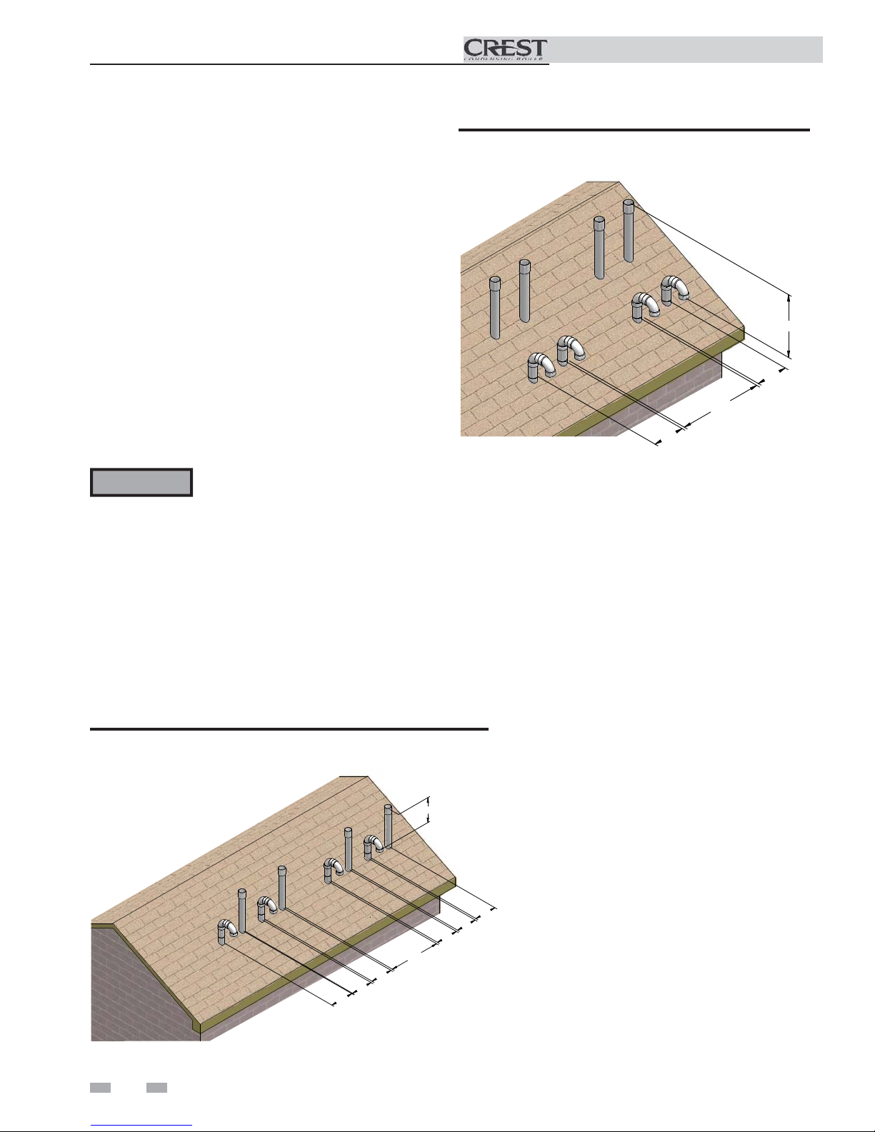
Multiple vent/air terminations
1. When terminating multiple Crest boilers, terminate
each vent/air connection as described in this manual
(FIG. 3-3).
WARNING
Terminate all vent pipes at the same height
and all air pipes at the same height to
avoid recirculation of flue products and
the possibility of severe personal injury,
death, or substantial property damage.
Figure 3-4 Alternate Vertical Terminations with Multiple
Boilers
36” (914 MM)
12”
(305 MM)
36” (914 MM)
12”
(305 MM)
2. Place roof penetrations to obtain minimum clearance of
12 inches (305 mm) between edge of air intake elbow and
adjacent vent pipe of another boiler for U.S. installations
(see FIG. 3-3). For Canadian installations, provide
clearances required by CSA B149.1 Installation Code.
3. The air inlet of a Crest boiler is part of a direct vent
connection. It is not classified as a forced air intake with
regard to spacing from adjacent boiler vents.
Figure 3-3 Vertical Terminations with Multiple Boilers
36” (914 MM)
36” (914 MM)
12”
(305 MM)
12”
(305 MM)
12”
(305 MM)
12”
(305 MM)
12”
(305 MM)
12”
(305 MM)
20
 Loading...