

Page 1
PROFESSIONAL
POWER AMPLIFIERS
™
OWNER’S MANUAL
Page 2
Intended to alert the user to the presence of uninsulated “dangerous voltage” within the product’s
enclosure that may be of sufficient magnitude to constitute a risk of electric shock to persons.
Intended to alert the user of the presence of important operating and maintenance (servicing)
instructions in the literature accompanying the product.
CAUTION: Risk of electrical shock — DO NOT OPEN!
CAUTION: To reduce the risk of electric shock, do not remove cover. No user serviceable parts inside. Refer
servicing to qualified service personnel.
WARNING: To prevent electrical shock or fire hazard, do not expose this appliance to rain or moisture. Before
using this appliance, read the operating guide for further warnings.
Este símbolo tiene el propósito, de alertar al usuario de la presencia de “(voltaje) peligroso” sin aisla
miento dentro de la caja del producto y que puede tener una magnitud suficiente como para constituir
riesgo de descarga eléctrica.
Este símbolo tiene el propósito de alertar al usario de la presencia de instruccones importantes sobre la
operación y mantenimiento en la información que viene con el producto.
PRECAUCION: Riesgo de descarga eléctrica ¡NO ABRIR!
PRECAUCION: Para disminuír el riesgo de descarga eléctrica, no abra la cubierta. No hay piezas útiles dentro.
Deje todo mantenimiento en manos del personal técnico cualificado.
ADVERTENCIA: Para evitar descargas eléctricas o peligro de incendio, no deje expuesto a la lluvia o humedad
este aparato Antes de usar este aparato, Iea más advertencias en la guía de operación.
Ce symbole est utilisé dans ce manuel pour indiquer à l’utilisateur la présence d’une tension dangereuse
pouvant être d’amplitude suffisante pour constituer un risque de choc électrique.
Ce symbole est utilisé dans ce manuel pour indiquer à l’utilisateur qu’il ou qu’elle trouvera d’importantes
instructions concernant l’utilisation et l’entretien de l’appareil dans le paragraphe signalé.
ATTENTION: Risques de choc électrique — NE PAS OUVRIR!
ATTENTION: Afin de réduire le risque de choc électrique, ne pas enlever le couvercle. Il ne se trouve à l’intérieur
aucune pièce pouvant être reparée par l’utilisateur. Confiez I’entretien et la réparation de l’appareil à un réparateur
Peavey agréé.
AVERTISSEMENT: Afin de prévenir les risques de décharge électrique ou de feu, n’exposez pas cet appareil à
la pluie ou à l’humidité. Avant d’utiliser cet appareil, lisez attentivement les avertissements supplémentaires de ce
manuel.
Dieses Symbol soll den Anwender vor unisolierten gefährlichen Spannungen innerhalb des Gehäuses
warnen, die von Ausreichender Stärke sind, um einen elektrischen Schlag verursachen zu können.
Dieses Symbol soll den Benutzer auf wichtige Instruktionen in der Bedienungsanleitung aufmerksam
machen, die Handhabung und Wartung des Produkts betreffen.
VORSICHT: Risiko — Elektrischer Schlag! Nicht öffnen!
VORSICHT: Um das Risiko eines elektrischen Schlages zu vermeiden, nicht die Abdeckung enfernen. Es befin
den sich keine Teile darin, die vom Anwender repariert werden könnten. Reparaturen nur von qualifiziertem
Fachpersonal durchführen lassen.
ACHTUNG: Um einen elektrischen Schlag oder Feuergefahr zu vermeiden, sollte dieses Gerät nicht dem Regen
oder Feuchtigkeit ausgesetzt werden. Vor Inbetriebnahme unbedingt die Bedienungsanleitung lesen.
2
Page 3
IMPORTANT SAFETY INSTRUCTIONS
WARNING: When using electrical products, basic cautions should always be followed, including the following:
1. Read these instructions.
2. Keep these instructions.
3. Heed all warnings.
4. Follow all instructions.
5. Do not use this apparatus near water.
6. Clean only with a dry cloth.
7. Do not block any of the ventilation openings. Install in accordance with manufacturer’s instructions.
8. Do not install near any heat sources such as radiators, heat registers, stoves or other apparatus (including
amplifiers) that produce heat.
9. Do not defeat the safety purpose of the polarized or grounding-type plug. A polarized plug has two blades with
one wider than the other. A grounding type plug has two blades and a third grounding plug. The wide blade or
third prong is provided for your safety. If the provided plug does not fit into your outlet, consult an electrician for
replacement of the obsolete outlet.
10. Protect the power cord from being walked on or pinched, particularly at plugs, convenience receptacles, and the
point they exit from the apparatus.
11. Note for UK only: If the colors of the wires in the mains lead of this unit do not correspond with the terminals in your
plug‚ proceed as follows:
a) The wire that is colored green and yellow must be connected to the terminal that is marked by the letter E‚ the
earth symbol‚ colored green or colored green and yellow.
b) The wire that is colored blue must be connected to the terminal that is marked with the letter N or the color black.
c) The wire that is colored brown must be connected to the terminal that is marked with the letter L or the color red.
12. Only use attachments/accessories provided by the manufacturer.
13. Use only with a cart, stand, tripod, bracket, or table specified by the manufacturer, or sold with the apparatus. When
a cart is used, use caution when moving the cart/apparatus combination to avoid injury from tip-over.
14. Unplug this apparatus during lightning storms or when unused for long periods of time.
15. Refer all servicing to qualified service personnel. Servicing is required when the apparatus has been damaged
in any way, such as power-supply cord or plug is damaged, liquid has been spilled or objects have fallen into the
apparatus, the apparatus has been exposed to rain or moisture, does not operate normally, or has been dropped.
16. Never break off the ground pin. Write for our free booklet “Shock Hazard and Grounding.” Connect only to a power
supply of the type marked on the unit adjacent to the power supply cord.
17. If this product is to be mounted in an equipment rack, rear support should be provided.
18. Exposure to extremely high noise levels may cause a permanent hearing loss. Individuals vary considerably in
susceptibility to noise-induced hearing loss, but nearly everyone will lose some hearing if exposed to sufficiently
intense noise for a sufficient time. The U.S. Government’s Occupational and Health Administration (OSHA) has
specified the following permissible noise level exposures:
Duration Per Day In Hours Sound Level dBA, Slow Response
8 90
6 92
4 95
3 97
2 100
1
1 105
According to OSHA, any exposure in excess of the above permissible limits could result in some hearing loss. Ear plugs or protectors to
the ear canals or over the ears must be worn when operating this amplification system in order to prevent a permanent hearing loss, if
exposure is in excess of the limits as set forth above. To ensure against potentially dangerous exposure to high sound pressure levels, it is
recommended that all persons exposed to equipment capable of producing high sound pressure levels such as this amplification system be
protected by hearing protectors while this unit is in operation.
1
⁄2 102
1
⁄2 110
1
⁄4 or less 115
SAVE THESE INSTRUCTIONS!
xx
3
Page 4
WICHTIGE SICHERHEITSHINWEISE
ACHTUNG: Beim Einsatz von Elektrogeräten müssen u.a. grundlegende Vorsichtsmaßnahmen befolgt werden:
1. Lesen Sie sich diese Anweisungen durch.
2. Bewahren Sie diese Anweisungen auf.
3. Beachten Sie alle Warnungen.
4. Befolgen Sie alle Anweisungen.
5. Setzen Sie dieses Gerät nicht in der Nähe von Wasser ein.
6. Reinigen Sie es nur mit einem trockenen Tuch.
7. Blockieren Sie keine der Lüftungsöffnungen. Führen Sie die Installation gemäß den Anweisungen des Herstellers durch.
8. Installieren Sie das Gerät nicht neben Wärmequellen wie Heizungen, Heizgeräten, Öfen oder anderen Geräten (auch Verstärkern),
die Wärme erzeugen.
9. Beeinträchtigen Sie nicht die Sicherheitswirkung des gepolten Steckers bzw. des Erdungssteckers. Ein gepolter Stecker weist
zwei Stifte auf, von denen einer breiter ist als der andere. Ein Erdungsstecker weist zwei Stifte und einen dritten Erdungsstift auf.
Der breite Stift bzw. der dritte Stift dient Ihrer Sicherheit. Sollte der beiliegende Stecker nicht in Ihre Steckdose passen, wenden
Sie sich bitte an einen Elektriker, um die ungeeignete Steckdose austauschen zu lassen.
10. Schützen Sie das Netzkabel, sodass niemand darauf tritt oder es geknickt wird, insbesondere an Steckern oder Buchsen und
ihren Austrittsstellen aus dem Gerät.
11. Hinweis – Nur für Großbritannien: Sollte die Farbe der Drähte in der Netzleitung dieses Geräts nicht mit den Klemmen in Ihrem
Stecker übereinstimmen, gehen Sie folgendermaßen vor:
a) Der grün-gelbe Draht muss an die mit E (Symbol für Erde) markierte bzw. grüne oder grün-gelbe Klemme angeschlossen
werden.
b) Der blaue Draht muss an die mit N markierte bzw. schwarze Klemme angeschlossen werden.
c) Der braune Draht muss an die mit L markierte bzw. rote Klemme angeschlossen werden.
12. Verwenden Sie nur die vom Hersteller erhältlichen Zubehörgeräte oder Zubehörteile.
13. Verwenden Sie nur einen Wagen, Stativ, Dreifuß, Träger oder Tisch, der den Angaben des Herstellers entspricht oder zusammen
mit dem Gerät verkauft wurde. Wird ein Wagen verwendet, bewegen Sie den Wagen mit dem darauf befindlichen Gerät besonders
vorsichtig, damit er nicht umkippt und möglicherweise jemand verletzt wird.
14. Trennen Sie das Gerät während eines Gewitters oder während längerer Zeiträume, in denen es nicht benutzt wird, von der
Stromversorgung.
15. Lassen Sie sämtliche Wartungsarbeiten von qualifizierten Kundendiensttechnikern durchführen. Eine Wartung ist erforderlich,
wenn das Gerät in irgendeiner Art beschädigt wurde, etwa wenn das Netzkabel oder der Netzstecker beschädigt wurden,
Flüssigkeit oder Gegenstände in das Gerät gelangt sind, das Gerät Regen oder Feuchtigkeit ausgesetzt wurde, nicht normal
arbeitet oder heruntergefallen ist.
16. Der Erdungsstift darf nie entfernt werden. Auf Wunsch senden wir Ihnen gerne unsere kostenlose Broschüre „Shock Hazard and
Grounding“ (Gefahr durch elektrischen Schlag und Erdung) zu. Schließen Sie nur an die Stromversorgung der Art an, die am
Gerät neben dem Netzkabel angegeben ist.
17. Wenn dieses Produkt in ein Geräte-Rack eingebaut werden soll, muss eine Versorgung über die Rückseite eingerichtet werden.
18. Belastung durch extrem hohe Lärmpegel kann zu dauerhaftem Gehörverlust führen. Die Anfälligkeit für durch Lärm bedingten
Gehörverlust ist von Mensch zu Mensch verschieden, das Gehör wird jedoch bei jedem in gewissem Maße geschädigt, der über
einen bestimmten Zeitraum ausreichend starkem Lärm ausgesetzt ist. Die US-Arbeitsschutzbehörde (Occupational and Health
Administration, OSHA) hat die folgenden zulässigen Pegel für Lärmbelastung festgelegt:
8 90
6 92
4 95
3 97
2 100
1
1 105
Dauer pro Tag in Stunden Geräuschpegel dBA, langsame Reaktion
1
⁄2 102
1
1
⁄2 110
⁄4 oder weniger 115
Laut OSHA kann jede Belastung über den obenstehenden zulässigen Grenzwerten zu einem gewissen Gehörverlust führen. Sollte
die Belastung die obenstehenden Grenzwerte übersteigen, müssen beim Betrieb dieses Verstärkungssystems Ohrenstopfen oder
Schutzvorrichtungen im Gehörgang oder über den Ohren getragen werden, um einen dauerhaften Gehörverlust zu verhindern. Um sich vor
einer möglicherweise gefährlichen Belastung durch hohe Schalldruckpegel zu schützen, wird allen Personen empfohlen, die mit Geräten
arbeiten, die wie dieses Verstärkungssystem hohe Schalldruckpegel erzeugen können, beim Betrieb dieses Geräts einen Gehörschutz zu tra
gen.
BEWAHREN SIE DIESE SICHERHEITSHINWEISE AUF!
4
-
Page 5
INSTRUCTIONS IMPORTANTES DE SECURITE
ATTENTION: L’utilisation de tout appareil électrique doit être soumise aux precautions d’usage incluant:
1. Lire ces instructions.
2. Gardez ce manuel pour de futures références.
3. Prétez attention aux messages de précautions de ce manuel.
4. Suivez ces instructions.
5. N’utilisez pas cette unité proche de plans d’eau.
6. N’utilisez qu’un tissu sec pour le nettoyage de votre unité.
7. N’obstruez pas les systèmes de refroidissement de votre unité et installez votre unité en fonction des instructions
de ce manuel.
8. Ne positionnez pas votre unité à proximité de toute source de chaleur.
9. Connectez toujours votre unité sur une alimentation munie de prise de terre utilisant le cordon d’alimentation
fourni.
10. Protégez les connecteurs de votre unité et positionnez les cablages pour éviter toutes déconnexions accidentelles.
11. Note pour les Royaumes-Unis: Si les couleurs de connecteurs du cable d’alimentation ne correspond pas au guide
de la prise secteur, procédez comme suit:
a) Le connecteur vert et jaune doit être connectrer au terminal noté E, indiquant la prise de terre ou correspondant
aux couleurs verte ou verte et jaune du guide.
b) Le connecteur Bleu doit être connectrer au terminal noté N, correspondnat à la couleur noire du guide.
c) Le connecteur marron doit être connectrer au terminal noté L, correspondant à la couleur rouge du guide..
12. N’utilisez que des fixations approuvées par le fabriquant.
13. Lors de l’utilsation sur pied ou pole de support, assurez dans le cas de déplacement de l’ensemble enceinte/
support de prévenir tout basculement intempestif de celui-ci.
14. Il est conseillé de déconnecter du secteur votre unité en cas d’orage ou de durée prolongée sans utilisation.
15. Seul un technicien agréé par le fabriquant est à même de réparer/contrôler votre unité. Celle-ci doit être contrôlée si
elle a subit des dommages de manipulation, d’utilisation ou de stockage (humidité,…).
16. Ne déconnectez jamais la prise de terre de votre unité.
17. Si votre unité est destinée a etre montée en rack, des supports arriere doivent etre utilises.
18. Une exposition à de hauts niveaux sonores peut conduire à des dommages de l’écoute irréversibles. La suscep
tibilité au bruit varie considérablement d’un individu à l’autre, mais une large majorité de la population expériencera
une perte de l’écoute après une exposition à une forte puissance sonore pour une durée prolongée. L’organisme de
la santé américaine (OSHA) a produit le guide ci-dessous en rapport à la perte occasionnée:
-
Durée par Jour (heures) Niveau sonore moyen (dBA)
8 90
6 92
4 95
3 97
2 100
1
1 105
D’après les études menées par le OSHA, toute exposition au delà des limites décrites ce-dessus entrainera des pertes de l’écoute chez la
plupart des sujets. Le port de système de protection (casque, oreilette de filtrage,…) doit être observé lors de l’opération cette unité ou des
dommages irréversibles peuvent être occasionnés. Le port de ces systèmes doit être observé par toutes personnes susceptibles d’être expo
sées à des conditions au delà des limites décrites ci-dessus.
1
⁄2 102
1
⁄2 110
1
⁄4 ou inférieur 115
GARDEZ CES INSTRUCTIONS!
-
5
Page 6
INSTRUCCIONES IMPORTANTES PARA SU SEGURIDAD
CUIDADO: Cuando use productos electrónicos, debe tomar precauciones básicas, incluyendo las siguientes:
1. Lea estas instrucciones.
2. Guarde estas instrucciones.
3. Haga caso de todos los consejos.
4. Siga todas las instrucciones.
5. No usar este aparato cerca del agua.
6. Limpiar solamente con una tela seca.
7. No bloquear ninguna de las salidas de ventilación. Instalar de acuerdo a las instrucciones del fabricante.
8. No instalar cerca de ninguna fuente de calor como radiadores, estufas, hornos u otros aparatos (incluyendo amplificadores)
que produzcan calor.
9. No retire la patilla protectora del enchufe polarizado o de tipo “a Tierra”. Un enchufe polarizado tiene dos puntas, una
de ellas más ancha que la otra. Un enchufe de tipo “a Tierra” tiene dos puntas y una tercera “a Tierra”. La punta ancha (
la tercera ) se proporciona para su seguridad. Si el enchufe proporcionado no encaja en su enchufe de red, consulte a un
electricista para que reemplaze su enchufe obsoleto.
10. Proteja el cable de alimentación para que no sea pisado o pinchado, particularmente en los enchufes, huecos, y los puntos
que salen del aparato.
11. Nota para el Reino Unido solamente: Si los colores de los cables en el enchufe principal de esta unidad no corresponden
con los terminales en su enchufe‚ proceda de la siguiente manera:
a) El cable de color verde y azul debe ser conectado al terminal que está marcado con la letra E‚ el símbolo de Tierra
(earth)‚ coloreado en verde o en verde y amarillo.
b) El cable coloreado en azul debe ser conectado al terminal que está marcado con la letra N o el color negro.
c) El cable coloreado en marrón debe ser conectado al terminal que está marcado con la letra L o el color rojo.
12. Usar solamente añadidos/accesorios proporcionados por el fabricante.
13. Usar solamente un carro, pie, trípode, o soporte especificado por el fabricante, o vendido junto al aparato. Cuando se use
un carro, tenga cuidado al mover el conjunto carro/aparato para evitar que se dañe en un vuelco. No suspenda esta caja de
ninguna manera.
14. Desenchufe este aparato durante tormentas o cuando no sea usado durante largos periodos de tiempo.
15. Para cualquier reparación, acuda a personal de servicio cualificado. Se requieren reparaciones cuando el aparato ha sido
dañado de alguna manera, como cuando el cable de alimentación o el enchufe se han dañado, algún líquido ha sido
derramado o algún objeto ha caído dentro del aparato, el aparato ha sido expuesto a la lluvia o la humedad, no funciona de
manera normal, o ha sufrido una caída.
16. Nunca retire la patilla de Tierra.Escríbanos para obtener nuestro folleto gratuito “Shock Hazard and Grounding” (“Peligro
de Electrocución y Toma a Tierra”). Conecte el aparato sólo a una fuente de alimentación del tipo marcado al lado del cable
de alimentación.
17. Si este producto va a ser enracado con más equipo, use algún tipo de apoyo trasero.
18. La exposición a altos niveles de ruido puede causar una pérdida permanente en la audición. La susceptibilidad a la pérdida
de audición provocada por el ruido varía según la persona, pero casi todo el mundo perderá algo de audición si se expone
a un nivel de ruido suficientemante intenso durante un tiempo determinado. El Departamento para la Salud y para la
Seguridad del Gobierno de los Estados Unidos (OSHA) ha especificado las siguientes exposiciones al ruido permisibles:
Duración por Día en Horas Nivel de Sonido dBA, Respuesta Lenta
8 90
6 92
4 95
3 97
2 100
1
1 105
De acuerdo al OSHA, cualquier exposición que exceda los límites arriba indicados puede producir algún tipo de pérdida en la audición.
Protectores para los canales auditivos o tapones para los oídos deben ser usados cuando se opere con este sistema de sonido para preve
nir una pérdida permanente en la audición, si la exposición excede los límites indicados más arriba. Para protegerse de una exposición a
altos niveles de sonido potencialmente peligrosa, se recomienda que todas las personas expuestas a equipamiento capaz de producir altos
niveles de presión sonora, tales como este sistema de amplificación, se encuentren protegidas por protectores auditivos mientras esta uni
dad esté operando.
1
⁄2 102
1
⁄2 110
1
⁄4 o menos 115
-
-
GUARDE ESTAS INSTRUCCIONES!
6
Page 7

Introduction
ENGLISH
CM™ Series power amplifiers feature a unique amplification architecture
providing a host of user benefits including simplified operation and use in
multiple applications, as well as unsurpassed sonic quality and flexible power.
Easy to Use
Multiple Uses
Protection Circuits/Safety
ACL™
(Active Clip Limiting, or Voltage limiting)
IGM™
(Instantaneous Gain Modulation, or current limiting)
AUTORAMP
™
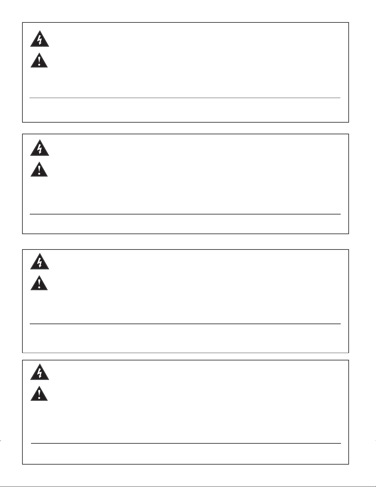
The CM 2204-AB (US model)/CM 2204-DV (European model) and CM
2208-AB (US model)/CM 2208-DV (European model) are easy to set up and
operate. Housed in a lightweight-but-rugged 16-gauge steel chassis, multiload architecture allows low impedance or 70 Volt operation without so
much as flipping a switch. Each channel outputs 220 Watts (70V or 8 Ohms,
or 160 Watts into 4 Ohms) for flexible system configuration, while front-toside cooling delivers low mains current draw, ensuring efficient operation in
a 2U rack space.
CM Series products comprise four-channel (CM 2204-AB/DV) and eightchannel (CM 2208-AB/DV) units (channels are independent). A host of
applications benefit from the use of multiple channel amplification, including
bars, clubs and restaurants; video conferencing systems; hotels and motels;
industrial installations; and retail stores, among others. One amplifier
for multiple applications provides a cost-effective solution, expansion
opportunities and unparalleled flexibility.
The CM Series has numerous circuit protection features, including:
Automatically reduces gain at the onset of clipping to prevent amplifier and
load damage.
Monitors load current to protect against overloading.
Gradually increases gain when the amplifier is turned on, preventing abrupt
turn-on level.
Other protection features:
Features at a glance:
Short circuit, DC voltage, comprehensive thermal management, current inrush turn-on/off transient and sub/ultrasonic input.
Some of the protection features are described in more detail later in this
manual but please note that improper use can be dangerous to the user as
well as the unit. These amplifiers are very high-powered and can produce
high voltages and sizable currents. Always use safe operating techniques
when operating these amplifiers but we also encourage you to read this
manual thoroughly.
• 4- or 8-channel power amp systems—220 Watts RMS per channel
(70 Volts)
• Low-Z (4 or 8 Ohms) or 70 Volt output
• Input connectors: balanced three-pin Phoenix
• Output connectors: two-pin Phoenix
• Full range of protection circuits including ACL, IGM and AUTORAMP
• 16-gauge steel chassis
• 2U rack space height
• CM 2204-AB/DV: 34 lbs./35.5 lbs.
CM 2208-AB/DV: 36.5 lbs./38.0 lbs.
• Front-to-side cooling
• Front-panel LED indicators per channel: signal, clip, and protect
• Input and output mating connectors are included
7
Page 8

Introduction
Unpacking
Mounting
Cooling Requirements
Upon unpacking, inspect the amplifier. If you find any damage, notify your
supplier immediately. Only the consignee may institute a claim with the
carrier for damage incurred during shipping. Be sure to save the carton
and all packing materials. Should you ever need to ship the unit back to
Crest Audio, one of its offices, service centers or the supplier, use only the
original factory packing. If the shipping carton is unavailable, contact Crest
Audio to obtain a replacement.
The CM™ Series power amplifiers will mount in standard 19" racks.
The CM Series power amplifiers use a forced-air cooling system to maintain
a low, even operating temperature. Air is drawn into the amplifier via a
fan located in the front of the unit and courses through the cooling fins of
the heat sink. The air then exits through the sides of the chassis. If the heat
sinks get too hot‚ a sensor circuit will activate the protective muting system
to protect the amplifier. When the internal temperature reaches a safe level‚
the amplifier will automatically return to normal operation. It is important
that both the front and the side of the unit have adequate space to allow
the cooling air to enter and escape. If the amp is rack mounted, do not use
doors or covers on the front of the rack; the intake air must flow without
resistance. If you are using racks with closed backs, make sure that there
is one (1) standard rack space opening for every three mounted power
amplifiers. If not rack mounted‚ allow 6" of clearance on all sides.
8
Page 9
Operating Precautions
Make sure the mains voltage is correct and is the same as that printed on
the rear of the amplifier. Damage caused by connecting the amplifier to
improper AC voltage is not covered by any warranty.
Note: Always turn off and disconnect the amplifier from mains voltage
before making audio connections. Also, as an extra precaution, turn down
the attenuators before powering up.
It is always a good idea to have the gain controls turned down while
powering up to prevent speaker damage if there is a high signal level at the
inputs. Whether you buy or make them, use good-quality connections, input
cables and speaker cables, along with good soldering technique, to ensure
trouble-free operation. Most intermittent problems are caused by faulty
cables.
Consult the Wire Gauge Chart (below) to determine proper gauges for
various load impedances and cable lengths. Remember that cable impedance
robs amplifier power in two ways: power lost directly to resistance (I2R
loss), and by raising the total load impedance.
W I R E G A U G E C H A R T
Cable Length
(In Feet)
5 18 .79 1.58
16 .50 1.00
14 .31 .62
12 .20 .40
10 .125 .25
10 18 1.58 3.16
16 1.00 2.00
14 .62 1.25
12 .40 .80
10 .25 .50
40 18 8.00 12.60
16 4.00 8.00
14 2.50 5.00
12 1.60 3.20
10 1.00 2.00
8 .625 1.25
80 16 8.00 16.00
14 5.00 10.00
12 3.20 6.40
10 2.00 4.00
Stranded Wire Gauge
(AWG)
Power Loss into
8 Ohms (%)
Power Loss into
4 Ohms (%)
9
Page 10
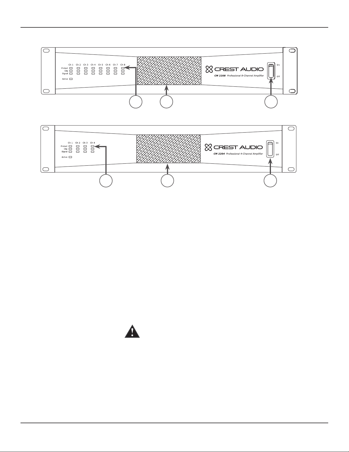
Front Panel
1 2 3
1 2 3
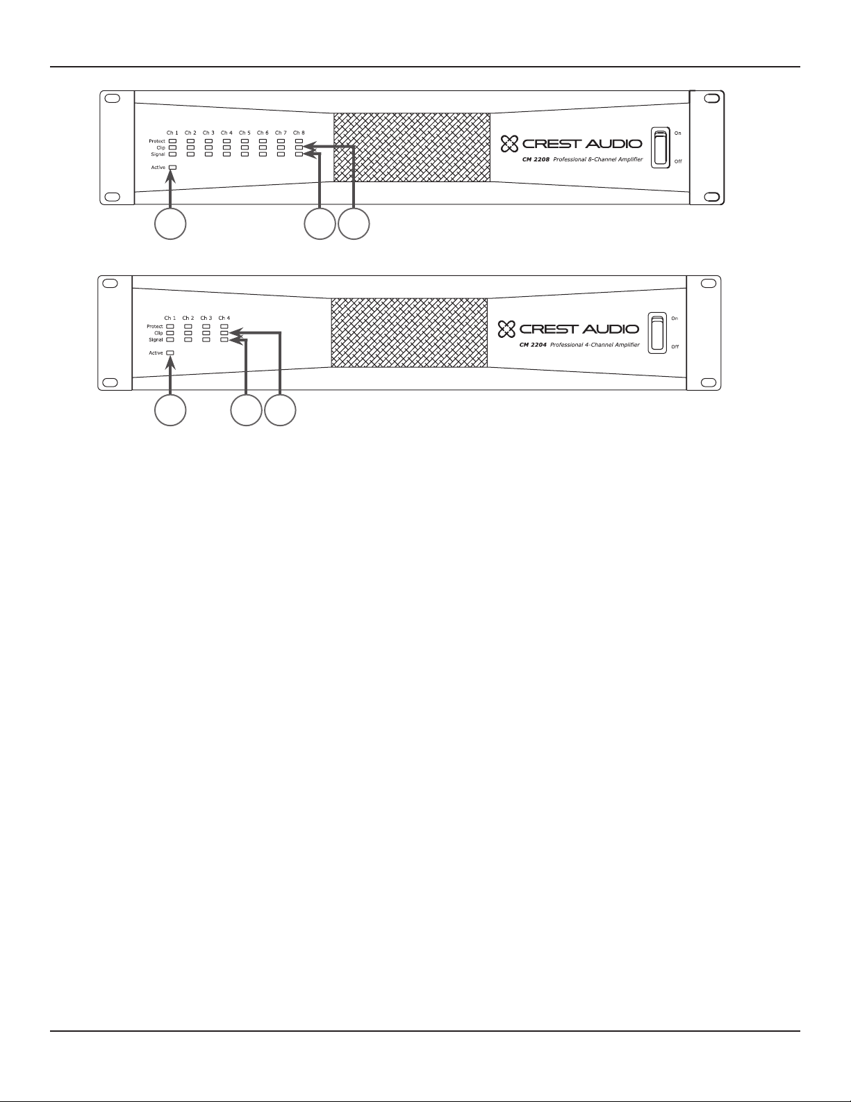
(1) Power Indicator
(2) Signal Indicators
(3) Clip Indicators
The green LED indicates that AC power is supplied to the unit and the
power switch is ON.
Green LEDs indicate significant signal presence on that channel output.
The Signal Indicator illuminates only when an output signal is 1 Watt or
higher (at 70V). Therefore, it is possible to have an acceptably strong signal
without the Signal Indicator illuminating.
The Clip Indicator LED illuminates yellow when the CM 2204/CM 2208
experiences excessive voltage or current into the load. When the amplifier
™
output reaches its limits, Active Clip Limiting (ACL
) will attempt to
compress the signal, causing the Clip LED to illuminate momentarily.
An over-current condition is more likely to occur with low impedance
™
speakers. For more information on clipping, see the IGM
and ACL
descriptions on page 7.
Upon continuous clipping, the unit will go into Protect (see # 4 below)
for one second and check the clipping condition. If the unit experiences a
persistent clipping condition, the unit will go into Protect permanently for
that channel, indicated by the Protect LED blinking steadily. In this case, to
bring that channel out of Protect mode, it is necessary to cycle power by
turning the unit OFF and then ON. If the Protect LED continues to blink
after power is restored, it is likely that the channel is damaged and service
to the unit is required.
10
Page 11
Front Panel
(4) Protect Indicators
4
4
6
6
5
5
Upon powering up the unit, the Protect LEDs illuminate momentarily and
then turn off one channel at a time and then remain off. During normal
operation, an over-current condition can occur if the amplifier is being
overdriven to the point where clipping is continuous or from a short circuit
in the speaker output. The Protect LED will illuminate red when one of
these conditions occurs.
™
The internal temperature of CM
Series amplifiers is 65º celsius. Should
the unit exceed this temperature, the amplifier will go into thermal protect
mode (generally, this would only occur if the internal fan fails). If the
amplifier has a thermal fault condition‚ all LEDs will illuminate. When the
amplifier cools down, the unit will restart automatically.
(5) AC Power Switch
(6) Cooling Air Vent
CM Series power amplifiers have a standard AC switch on the front panel.
Warning: The power switch does not break both sides of the
line and under certain conditions hazardous energy can be present
when the switch is in the OFF position.
The CM Series is designed to operate under extreme conditions. The
front-panel design features a duct that allows air to be drawn in by the fan,
circulated through the removable filter (for cleaning) and finally dispersing
out the sides of the unit. The openings on the front and sides of the unit
should never be blocked. It is recommended that the removable filter be
cleaned with compressed air.
11
Page 12
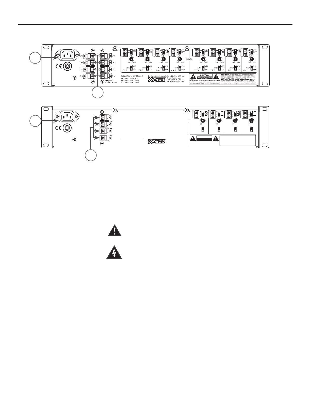
Rear Panel
0dB
-6
-
0dB
-6
-
0dB
-6
-
0dB
-6
-
www.crestaudio.com
Crest Audio, Inc.
Fair Lawn, NJ USA
Designed and manufactured in the USA by
:
Outputs
Class 2 Wiring
Inputs
Gain
Ch 4
0dB
x40
Gain
Ch 3
0dB
x40
HPF
Gain
Ch 2
0dB
x40
Gain
Ch 1
0dB
x40
HPF
WARNING:
TO REDUCE THE RISK OF FIRE OR ELECTRIC
SHOCK, THIS APPARATUS SHOULD NOT BE EXPOSED TO RAIN OR
MOISTURE AND OBJECTS FILLED WITH LIQUIDS, SUCH AS VASES,
SHOULD NOT BE PLACED ON THIS APPARATUS.
AVIS:
DANS LE BUT DE REDUIRE LES RISQUES D’INCENDIE OU
DE DECHARGE ELECTRIQUE, CET APPREIL NE DOIT PAS ETRE
EXPOSE A LA PLUIE OU A L’HUMIDITE ET AUCUN OBJET REMPLI
DE LIQUIDE, TEL QU’UN VASE, NE DOIT ETRE POSE SUR CELUI-CI.
AVIS:
RISQUE DE CHOC ÉLECTRIQUE-NE PAS OUVRIR
CAUTION
RISK OF ELECTRIC SHOCK
DO NOT OPE
N
MOUNT IN RACK O NLY.
INSTALLER SUR SUPPO RT DE MONTAGE SEUL EMENT.
220 Watts @ 70.7 V
220 Watts @ 8 Ohms
160 Watts @ 4 Ohms
Output Power per Channel
+
Ch 1
+
Ch 2
+
Ch 3
+
Ch 4
7
7
8
8
(7) AC Mains Power Receptacle
(8) Channel Outputs
This is a standard IEC power connector. An AC mains cord having the
appropriate AC plug and ratings for the intended operating voltage is
included in the carton. The mains cord should be connected to the amplifier
before connecting to a suitable AC outlet.
AC Mains Cord
The mains cord supplied with the unit is a heavy duty‚ three conductor-type
with a conventional 120 VAC plug (230 VAC European) with ground pin.
Never break off the ground pin on any equipment. It is provided for your
safety. If the outlet used does not have a ground pin‚ a suitable grounding
adapter should be used and the third wire should be properly grounded.
NOTE FOR UK ONLY:
If the colors of the wires in the mains lead of this unit do not correspond
with the colored markings identifying terminals in your plug, proceed as
follows: (1) The wire that is colored green and yellow must be connected to
the terminal marked by the letter E, or by the earth symbol, or colored green
or green and yellow. (2) The wire that is colored blue must be connected to
the terminal that is marked with the letter N, or colored black. (3) The wire
that is colored brown must be connected to the terminal that is marked with
the letter L or colored red.
The outputs are two-pin Phoenix connectors. Connect the loudspeaker system to the respective positive (+) and ground (-) terminals as indicated on
the unit. An exception is when the unit is in Bridged Mode, whereupon a
speaker is connected to two positive terminals on the outputs of two chan
nels.
12
-
Page 13
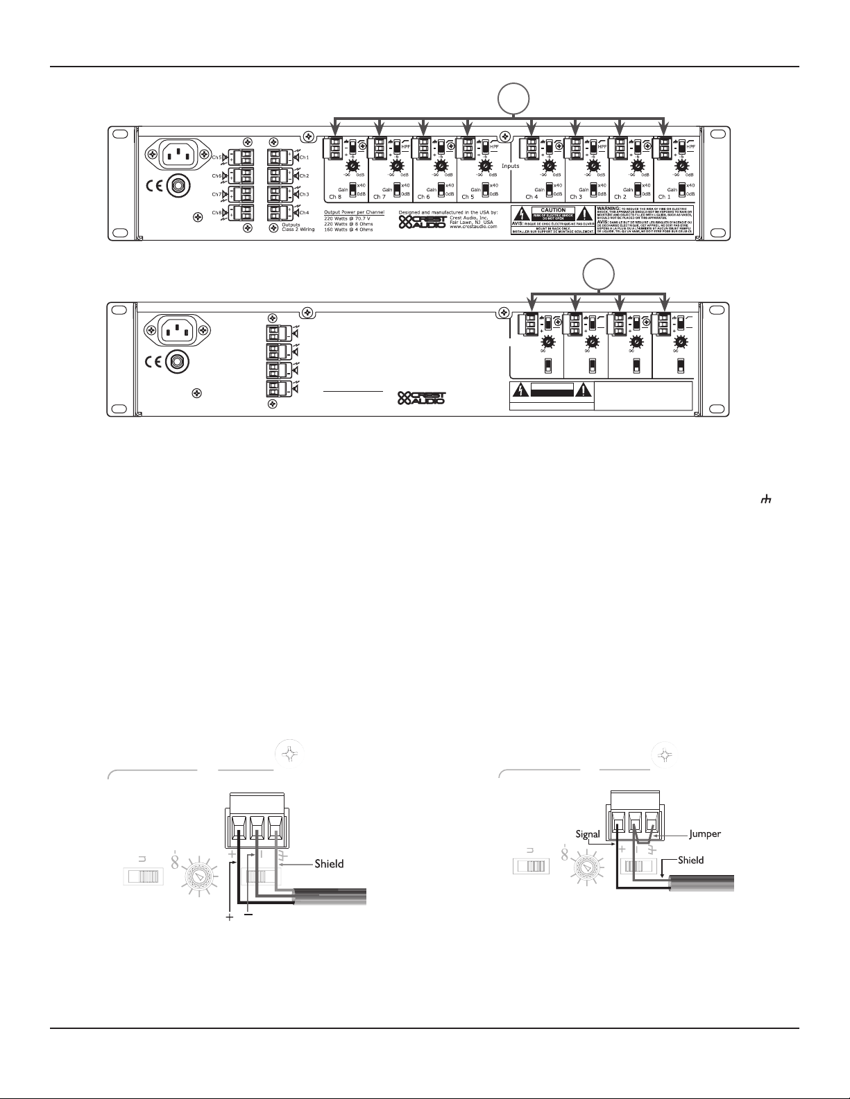
Rear Panel
Inputs
Ga
i
n
C
h
4
0dB
x
4
0
0d
B
-6
0d
B
-6
Inputs
Ga
i
n
C
h
4
0dB
x
4
0
0dB
-6
-
0dB
-6
-
0dB
-6
-
0dB
-6
-
www.crestaudio.com
Crest Audio, Inc.
Fair Lawn, NJ USA
Designed and manufactured in the USA by
:
Outputs
Class 2 Wiring
Inputs
Gain
Ch 4
0dB
x40
Gain
Ch 3
0dB
x40
HPF
Gain
Ch 2
0dB
x40
Gain
Ch 1
0dB
x40
HPF
WARNING:
TO REDUCE THE RISK OF FIRE OR ELECTRIC
SHOCK, THIS APPARATUS SHOULD NOT BE EXPOSED TO RAIN OR
MOISTURE AND OBJECTS FILLED WITH LIQUIDS, SUCH AS VASES,
SHOULD NOT BE PLACED ON THIS APPARATUS.
AVIS:
DANS LE BUT DE REDUIRE LES RISQUES D’INCENDIE OU
DE DECHARGE ELECTRIQUE, CET APPREIL NE DOIT PAS ETRE
EXPOSE A LA PLUIE OU A L’HUMIDITE ET AUCUN OBJET REMPLI
DE LIQUIDE, TEL QU’UN VASE, NE DOIT ETRE POSE SUR CELUI-CI.
AVIS:
RISQUE DE CHOC ÉLECTRIQUE-NE PAS OUVRIR
CAUTION
RISK OF ELECTRIC SHOCK
DO NOT OPEN
MOUNT IN RACK O NLY.
INSTALLER SUR SUPPO RT DE MONTAGE SEUL EMENT.
220 Watts @ 70.7 V
220 Watts @ 8 Ohms
160 Watts @ 4 Ohms
Output Power per Channel
+
Ch 1
+
Ch 2
+
Ch 3
+
Ch 4
9
9
(9) Channel Inputs
The inputs are balanced, three-pin Phoenix connectors. Connect the
incoming signals to the respective positive (+), negative (-) and ground ( )
terminals as indicated on the unit. Channel input sensitivity is 0dBu (0.775V)
when the 0dB gain setting is selected. This equates to a gain of 90.3x. Gain
can also be decreased to x40 with the gain setting switch (see # 12 Gain
Select). If using bridged, see the Bridged Mode section.
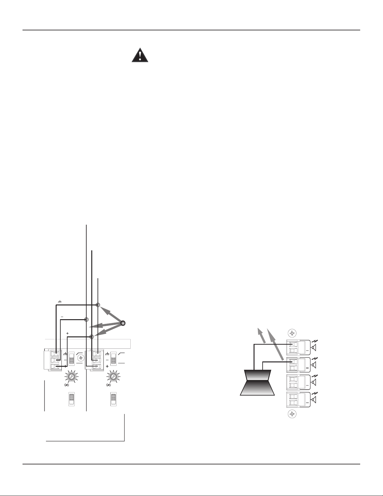
Input Connections
The Phoenix connectors are wired as: Pin 1 is positive; Pin 2 is negative;
and Pin 3 is chassis ground. Normally balanced inputs are wired using
two-conductor shielded cable as shown in the following diagram. For unbalanced (single-ended) inputs‚ the single conductor is wired to Pin 1 and
the shield is connected to Pins 2 & 3 as shown in the following diagram.
Balanced Unbalanced
13
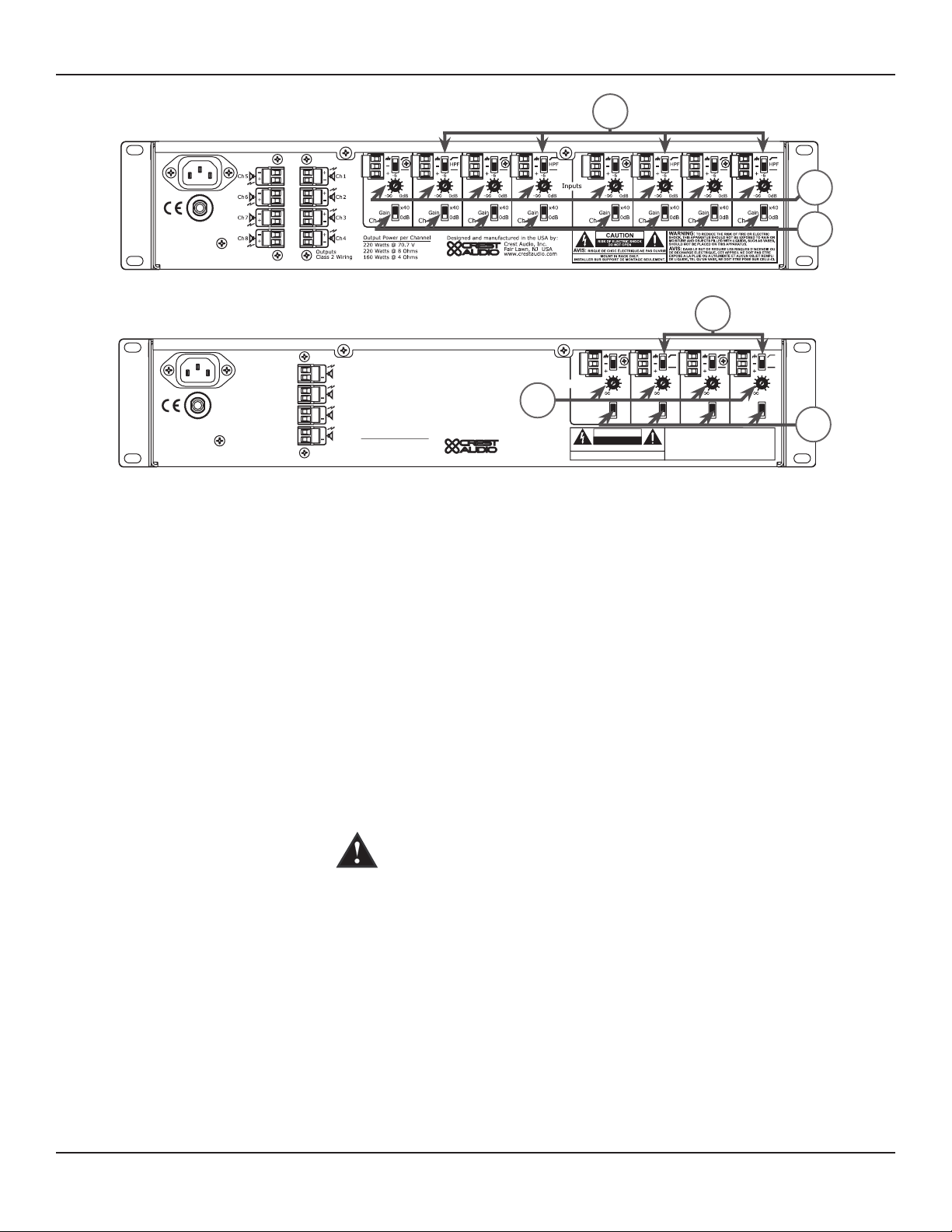
Page 14
Rear Panel
0dB
-6
-
0dB
-6
-
0dB
-6
-
0dB
-6
-
www.crestaudio.com
Crest Audio, Inc.
Fair Lawn, NJ USA
Designed and manufactured in the USA by
:
Outputs
Class 2 Wiring
Inputs
Gain
Ch 4
0dB
x40
Gain
Ch 3
0dB
x40
HPF
Gain
Ch 2
0dB
x40
Gain
Ch 1
0dB
x40
HPF
WARNING:
TO REDUCE THE RISK OF FIRE OR ELECTRIC
SHOCK, THIS APPARATUS SHOULD NOT BE EXPOSED TO RAIN OR
MOISTURE AND OBJECTS FILLED WITH LIQUIDS, SUCH AS VASES,
SHOULD NOT BE PLACED ON THIS APPARATUS.
AVIS:
DANS LE BUT DE REDUIRE LES RISQUES D’INCENDIE OU
DE DECHARGE ELECTRIQUE, CET APPREIL NE DOIT PAS ETRE
EXPOSE A LA PLUIE OU A L’HUMIDITE ET AUCUN OBJET REMPLI
DE LIQUIDE, TEL QU’UN VASE, NE DOIT ETRE POSE SUR CELUI-CI.
AVIS:
RISQUE DE CHOC ÉLECTRIQUE-NE PAS OUVRIR
CAUTION
RISK OF ELECTRIC SHOCK
DO NOT OPEN
MOUNT IN RACK O NLY.
INSTALLER SUR SUPPO RT DE MONTAGE SEUL EMENT.
220 Watts @ 70.7 V
220 Watts @ 8 Ohms
160 Watts @ 4 Ohms
Output Power per Channel
+
Ch
1
+
Ch
2
+
Ch
3
+
Ch
4
10
11
12
10
11
12
(10) High-Pass Filter
(11) Stepped Attenuators
(12) Gain Select
(13) Circuit Breaker
This two-position switch provides enabling or bypass of a high-pass filter,
which is available on each channel input. In the top position (enabled), the
high-pass filter cutoff is 70 Hz. In the bottom position (disabled), the input
frequency range is extended down to 1 Hz. The top and bottom positions
of the high-pass filter are indicated on the unit by a sloped line and a flat
line, respectively.
Each channel input features a 21-position stepped attenuator ranging from
negative infinity to 0 dB. The “halfway” position of the stepped attenuator is
-6 dB, as indicated on the unit.
An individual Gain Select is available on each channel input. This twoposition switch can be set at 0 dB in the bottom position and x40 in the
top position.
If the circuit breaker pops, turn the unit OFF and let sit for one minute and
then turn back ON. If the circuit breaker pops a second time, the unit may
be damaged and should be returned to a Crest Audio dealer for servicing.
14
Page 15
Bridged Mode
Wire Connections
+ input
GND inpu
t
- input
0dB
-6
-
0dB
-6
-
Inputs
Gain
Ch 2
0dB
x40
Gain
Ch 1
0dB
x40
HPF
TO REDUCE THE RISK OF FIRE OR ELECTRIC
AP
PARATUS SHOULD NOT BE EXPOSED TO RAIN OR
AND OBJECTS FILLED WITH LIQUIDS, SUCH AS VASES,
APPARATUS.
D INCENDIE OU
APPREIL NE DOIT PAS ETRE
A LA PLUIE OU A L HUMIDITE ET AUCUN OBJET REMPLI
L QU UN VASE
, NE DOIT ETRE POSE SUR CELUI-CI.
Input
Input
Input
Outputs
Class 2 Wiring
+
Ch 1
+
Ch 2
+
Ch 3
+
Ch 4
Connect only to “+” terminals
Speaker
A pair of amplifier channels may be bridged together to make a single
output with a power rating equal to the sum of both channel power ratings
at twice the load rating of a single channel. In other words‚ bridging two
amplifiers rated for 160 Watts into 4 Ohms will produce 320 Watts into 8
Ohms.
In Bridged Mode‚ the channels operate at opposite polarity from each other
so that one channel pushes and the other pulls equally. This mode sends the
input signal to one channel and the same signal with its polarity reversed to
the other channel for any two channels (1/2, 3/4 on the CM 2204-AB/DV or
1/3, 2/5, 4/6, 7/8 on the CM 2208-AB/DV). For example, to bridge channels
1 and 2, connect the input signal to the channel 1 input connector using
the standard connections (see # 9, Channel Inputs in Back Panel section).
On channel 2 however, reverse the positive and negative input connections
so that the positive (+) connector is connected channel 2’s negative (-)
receptacle and the negative input connector (-) is connected to channel 2’s
positive (+) receptacle.
Both channel level controls (in this example‚ 1 & 2) MUST be used to
control the signal level and both MUST be set at the same position.
15
Page 16
Outputs in Bridged Mode
The loudspeaker load is connected only to the designated positive (+)
output terminals of the bridged channels. NEVER ground either side of
the loudspeaker load cable when the amplifier is in Bridged Mode as both
sides are “hot.” If an output patch panel is used‚ all connections must be
isolated from each other and from the panel. When using the low-Z output‚
the minimum nominal load impedance in Bridged Mode is 8 Ohms; this is
equivalent to driving both bridged channels at 4 Ohms. When using the 70
Volt output‚ the bridged output is 140 Volts and the minimum load imped
ance in Bridged Mode is 50 Ohms. Driving loads of lesser impedance may
activate the protection circuits. See Output Modes section for more infor
mation.
Regardless of operating mode‚ NEVER connect the amplifier outputs
Note:
together.
-
-
Output Modes
Caution:
Warning:
Output voltages greater than 120 V RMS are available between the bridged
terminals. CLASS 3 wiring must be used in accordance with national and
local codes to connect the loudspeaker system.
The loudspeaker output connections of this amplifier are hazardous when
live and present a shock hazard when they are energized. Take the following
precautions:
1. Do not touch any bare wires that are connected to the loudspeaker
output connectors.
2. Use insulated loudspeaker cables and touch-proof connectors on the
loudspeakers.
3. Do not attempt to make connections to the output connectors or the
loudspeaker connectors when the amplifier is turned ON.
4. Double-check all connections and make sure there are no exposed wires
or connectors before turning the on amplifier.
5. Make sure there are no frayed cables or wires and that all connections
are tight and secure every time before turning the amplifier on.
6. External wiring connected to these terminals requires installation by a
trained person or the use of ready-made leads or cords.
Each channel of the CM™ 2204-AB/DV or CM 2208-AB/DV can be used in
Direct Drive (Low-Z, 70V or 140V) or Isolated Drive (100V of 50V) appli
-
cations.
Low-Z
70V
100V/50V
This mode allows each output of the channel pair to drive a 4 or 8 Ohm
loudspeaker load. Use Bridged Mode (See Bridged Mode section) to deliver
the power of both channels to a single 8 Ohm load such as a subwoofer.
This mode allows each output of the channel pair to directly drive a 70
Volt constant-voltage audio distribution system. Use the Bridged Mode (See
Bridged Mode section) to deliver the power of both channels to a 140 Volt
constant-voltage audio distribution system.
The output of the CM 2204-AB/DV and CM 2208-AB/DV can be converted
to 100V or 50V with the optional CMX4-50/CMX4-100/CMX8-50/CMX8100 accessories, respectively.
16
Page 17
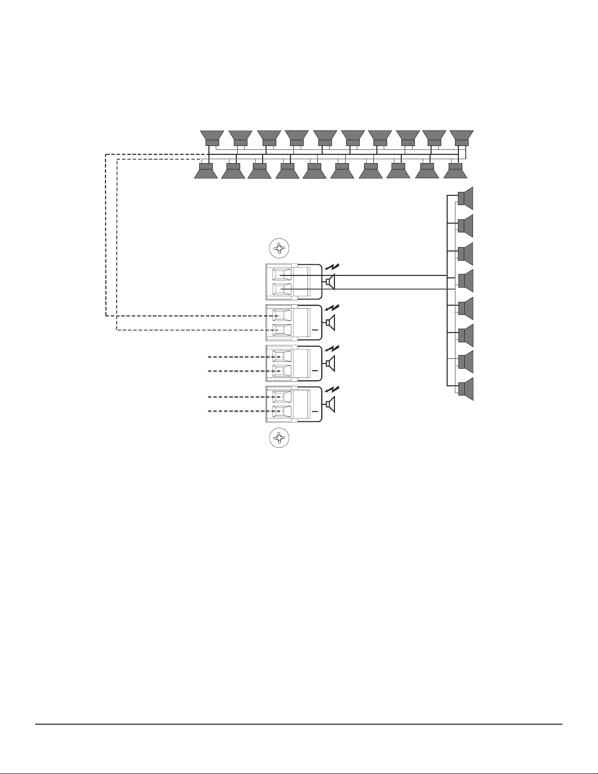
20 speakers @ 10 Watts each = 200 Watts
+
+
-
+
-
+
-
+
-
+
-
+
-
+
-
+
-
+
-
+
-
+
-
+
-
+
-
+
-
+
-
+
-
+
-
8 speakers @ 25 Watts each = 200 Watts
+
Low Z or
70 V Line
Low Z or
70 V Line
+
-
-
+
+
-
-
70 V Line
70 V Line
Outputs
Class 2 Wirin
g
+
Ch1
+
Ch2
+
Ch3
+
Ch4
+
-
-
-
+
+
-
+
-
+
-
+
-
+
-
+
-
+
-
+
-
+
-
-
Example of a 70 Volt constant-voltage distribution system
17
Page 18

SPECIFICATIONS
Specification CM™ 2208 CM 2204
Non-Bridged Mode
Rated Power (one channel driven)
4 Ohms 160 Watts 160 Watts
8 Ohms 240 Watts 245 Watts
70 Volts (24 Ohms) 230 Watts 220 Watts
Rated Power (all channels driven)
4 Ohms 150 Watts 155 Watts
8 Ohms 210 Watts 240 Watts
70 Volts (24 Ohms) 170 Watts 180 Watts
Minimum Load Impedance 4 Ohms 4 Ohms
Bridged Mode
Rated Power (one channel driven)
8 Ohms 320 Watts 320 Watts
140 Volts 460 Watts 440 Watts
Rated Power (all channels driven)
8 Ohms 300 Watts 310 Watts
140 Volts 340 Watts 360 Watts
Minimum Load Impedance 8 Ohms 8 Ohms
Frequency Response (HPF off)
-1 dB @ 1 Watt (8 Ohm Load) 5 Hz–20 kHz 5 Hz–20 kHz
THD @ rated power‚ 1 kHz (70 V) <0.02% <0.02%
Damping Factor (8 Ohms) >200 >200
Input CMRR <-60 dB <-60 dB
Voltage Gain x40 or 0 dBu (x90) x40 or 0 dBu (x90)
Input Sensitivity (0 dBu setting) 0.775 V 0.775 V
Input Impedance 20 K Ohms balanced 20 K Ohms balanced
10 K Ohms unbalanced 10 K Ohms unbalanced
Noise and Hum
Below rated output‚ 22 Hz–22 kHz -97 dB -97 dB
18
Page 19

SPECIFICATIONS
Specification CM™ 2208 CM 2204
Current Consumption (Multiply current by 0.5 for 230 V units)
1/3 power, 70 V output 8.0 A 4.4 A
1/8 power, 70 V output 4.0 A 2.3 A
Idle <2 A <1 A
Thermal Emission
1/8 power, 70 V output 724 BTU/hr 473 BTU/hr
1/3 power, 70 V output 947 BTU/hr 621 BTU/hr
Controls
Front: AC switch
CM 2204, Rear: 4 channel input signal attenuators‚ 4 channel HPF select switches, 4 channel gain select switches
CM 2208, Rear: 8 channel input signal attenuators‚ 8 channel HPF select switches, 8 channel gain select switches
Indicator LEDs (front panel)
CM 2204: 4 clip‚ 4 signal‚ 4 protect, 1 power
CM 2208: 8 clip‚ 8 signal‚ 8 protect, 1 power
Protection
Over-temperature‚ DC‚ turn on/off transients‚ subsonic‚ short-circuit, over-current
Connectors
CM 2204, Input: Four 3-position Euro-style detachable terminal blocks
CM 2208, Input: Eight 3-position Euro-style detachable terminal blocks
CM 2204, Output: Four 2-position Euro-style detachable terminal blocks
CM 2208, Output: Eight 2-position Euro-style detachable terminal blocks
Construction
16-gauge steel-reinforced with 12-gauge rack ears
Dimensions
Height: 3.50" (8.84 cm); 2 EIA rack spaces
Width‚ front: 19.00" (48.26 cm)
Width‚ rear: 17.00" (43.18 cm)
Overall depth: 17.05" (43.31 cm)
Mounting depth: 16.63" (42.24 cm) behind front rack ears
Weight
CM 2204-AB: 34 lbs. (15.4 kg) CM2204-DV: 35.5 lbs. (16.1 kg)
CM 2208-AB: 36.5 lbs. (16.5 kg) CM2208-DV: 38 lbs. (17.2 kg)
Power Requirements
120 VAC 60 Hz (-AB versions)
230 VAC 50 Hz (-DV versions)
Test Conditions
120 VAC 60 Hz Line Input voltage maintained (-AB versions)
230 VAC 50 Hz Line Input voltage maintained (-DV versions)
19
Page 20

SERVICE AND SUPPORT
Support
Contact Us
Customer Service
Technical Support
Web Site
In the unlikely event that your amplifier develops a problem, it must be
returned to an authorized distributor or service center or shipped directly
to our factory.
To obtain service, contact your nearest Crest Audio Service Center,
Distributor, Dealer or any of the worldwide Crest Audio offices (available
online at www.crestaudio.com).
phone 201.475.4600 USA
email custsrv@crestaudio.com
phone 201.475.4600 USA
email techserve@crestaudio.com
www.crestaudio.com
Mail
Crest Audio Inc.
16-00 Pollitt Drive
Fair Lawn, NJ 07410 USA
20
Page 21

Einführung
DEUTSCH
Verstärker der CM™-Serie bieten eine einzigartige Verstärkerarchitektur
mit einer Vielzahl von Vorteilen für den Nutzer wie etwa der vereinfachte
Betrieb und der Einsatz bei zahlreichen Anwendungen sowie eine
unübertroffene Klangqualität und flexible Leistung.
Einfach zu bedienen
Vielseitiger Einsatz
Schutzschaltungen/Sicherheit
ACL™
(Active Clip Limiting oder Spannungsbegrenzung)
IGM™
(Instantaneous Gain Modulation oder
Leistungszufuhrbegrenzung)
Der CM 2204-AB (US-Modell)/CM 2204-DV (Europa-Modell) und der
CM 2208-AB (US-Modell)/CM 2208-DV (Europa-Modell) lassen sich ganz
einfach einstellen und bedienen. Die in einem leichten, aber dennoch soliden
Stahlgehäuse (Stärke 16) untergebrachte Multi-Load-Architektur erlaubt
einen niederohmigen oder einen 70-Volt-Betrieb (Wahlschalter). Die
Ausgangsleistung je Kanal beträgt 220 Watt (70 V oder 8 Ohm oder 160
Watts in 4 Ohm), was eine flexible Systemkonfiguration gestattet. Die FrontSeiten-Kühlung senkt den Stromverbrauch und gewährleistet den effizienten
Betrieb in einer 2HE-Rack-Anordnung.
Die CM-Serie umfasst Vierkanal- (CM 2204-AB/DV) und AchtkanalGeräte (CM 2208-AB/DV) (unabhängige Kanäle). Mehrkanal-Verstärker
sind in einer Vielzahl von Umgebungen einsetzbar, z.B. in Bars, Clubs und
Restaurants, Videokonferenzen, Hotels und Motels, Industriebetrieben und
Geschäften. Ein für mehrere Anwendungen geeigneter Verstärker stellt eine
kostengünstige Lösung dar und bietet Erweiterungsmöglichkeiten und eine
unerreichte Flexibilität
Die CM-Serie bietet zahlreiche Schutzschaltungsfunktionen, darunter:
Zur automatischen Gain-Reduzierung beim Einsetzen von Clipping, um
Beschädigungen an Verstärker und Lautsprechern zu vermeiden.
Überwacht den Laststrom zum Schutz vor Überlast.
AUTORAMP
™
Weitere Schutzfunktionen:
Der Gain wird beim Einschalten des Verstärkers schrittweise erhöht, um
abrupte Einschaltspitzen zu verhindern.
Kurzschluss, Gleichspannung, umfassende Wärmeregelung, Stromstoß, Ein/Ausschalt-Spannungsspitze und Unter-/Ultraschallsignale.
Einige Schutzfunktionen sind in diesem Handbuch an späterer Stelle
ausführlicher beschrieben. Beachten Sie jedoch, dass unsachgemäßer Einsatz
Gefahren sowohl für den Anwender als auch das Gerät birgt. Bei diesen
Geräten handelt es sich um Hochleistungsverstärker, die hohe Spannungsund Stromwerte abgeben können. Achten Sie beim Einsatz dieser Verstärker
immer auf sichere Betriebsverfahren und lesen Sie diese Anleitung bitte
sorgfältig durch
21
Page 22

Einleitung
Funktionen auf einen Blick:
Auspacken
• Vier- oder Achtkanal-Verstärkersystem – 200 Watt RMS pro Kanal
(70 Volt)
• Niederohmiger (4 oder 8 Ohm) oder 70-Volt-Ausgang
• Eingangsstecker: 3-Pin-Phoenix, symmetriert
• Ausgangsstecker: 2-Pin-Phoenix
• Umfangreiche Schutzschaltungen einschließlich ACL, IGM und
AUTORAMP
• Stahlgehäuse der Stärke 16
• 2 HE. Rack-Höhe
• CM 2204-AB/DV: 15,4 kg/16,1 kg 2208-AB/DV: 16,5 kg/17,2 kg
• Front-Seiten-Kühlung
• LED-Anzeigen für jeden Kanal auf der Vorderseite: Signal, Clip und
Protect
• Eingangs- und Ausgangs-Steckverbinder sind im Lieferumfang
enthalten
Untersuchen Sie den Verstärker beim Auspacken. Sollten Sie Beschädigungen
feststellen, informieren Sie unverzüglich Ihren Händler. Nur der
Empfänger kann gegenüber dem Spediteur einen Anspruch aufgrund von
Transportschäden geltend machen. Heben Sie den Karton und sämtliches
Verpackungsmaterial bitte auf. Sollte es irgendwann einmal erforderlich sein,
das Gerät zu Crest Audio oder zu einem unserer Büros, Service-Center
oder Händler zurückzuschicken, verwenden Sie dazu bitte ausschließlich die
Original-Werksverpackung. Sollte keine Versandverpackung mehr vorhanden
sein, bitten Sie Crest Audio um Ersatz
.
Montage
Kühlanforderungen
Die Verstärker der CM™-Serie werden in genormten 19”-Racks montiert.
Die Verstärker der CM-Serie arbeiten mit einem Fremdkühlsystem, das eine
niedrige gleichmäßige Betriebstemperatur gewährleistet. Luft wird durch die
Ventilatoren auf der Rückseite in das Gerät eingesaugt und läuft durch die
Kühlrippen des Kanalkühlkörpers. Die Luft tritt an den Seiten des Gehäuses
wieder aus. Werden die Kühlrippen zu heiß, aktiviert eine Sensorschaltung
das Stummschaltsystem zum Schutz des Verstärkers. Ist die Innentemperatur
wieder auf einen normalen Wert gesunken, schaltet der Verstärker
automatisch wieder in den Normalbetrieb um. Sowohl an der Front als auch
an der Seite des Gerätes muss genügend Platz für die zirkulierende Kühlluft
gelassen werden. Wird der Verstärker im Rack montiert, darf das Rack
vorne nicht mit Türen oder Abdeckungen verschlossen werden; die Zuluft
muss unbehindert strömen können. Werden Racks mit verschlossenen
Rückseiten verwendet, muss eine (1) Standard-Rackhöhe für je drei
montierte Verstärker offen gelassen werden. Wird das Gerät nicht im Rack
montiert, muss auf allen Seiten ein Abstand von 15 cm belassen werden.
22
Page 23

Sicherheitshinweise für den Betrieb
Achten Sie darauf, dass die Netzspannung korrekt ist und mit den Angaben
auf der Rückseite des Verstärkers übereinstimmt. Schäden, die aufgrund
des Anschlusses des Verstärkers an eine ungeeignete Wechselspannung
entstehen, werden nicht von der Garantie abgedeckt.
Hinweis: Schalten Sie den Verstärker immer aus und trennen Sie
ihn vom Netz, bevor Sie Audio-Geräte anschließen. Als zusätzliche
Vorsichtsmaßnahme sollten Sie vor dem Einschalten die Dämpfer
herunterdrehen.
Es empfiehlt sich, die Gain-Regler während des Einschaltens ausgedreht
zu lassen; dies verhindert eine Beschädigung der Lautsprecher, wenn an
den Eingängen hohe Signalpegel vorliegen. Ganz gleich, ob Sie sie kaufen
oder selber herstellen, verwenden Sie nur Anschlüsse, Eingangskabel und
Lautsprecherkabel guter Qualität, und gehen Sie beim Löten sorgfältig und
korrekt vor, um einen störungsfreien Betrieb zu gewährleisten. Die meisten
Probleme durch Ausfälle werden durch defekte Kabel verursacht.
Die geeigneten Durchmesser für verschiedene Lastimpedanzen und
Kabellängen finden Sie in der untenstehenden Kabelstärkentabelle. Denken
Sie daran, dass der Kabelwiderstand die Leistung des Verstärkers auf
zweifache Weise beeinträchtigt: Durch direkten Leistungsverlust aufgrund
des Widerstands (I2R-Verlust) und durch Anheben der Gesamtlastimpedanz.
W I R E G A U G E C H A R T
Kabellänge
(In Fuß)
5 18 .79 1.58
16 .50 1.00
14 .31 .62
12 .20 .40
10 .125 .25
10 18 1.58 3.16
16 1.00 2.00
14 .62 1.25
12 .40 .80
10 .25 .50
40 18 8.00 12.60
16 4.00 8.00
14 2.50 5.00
12 1.60 3.20
10 1.00 2.00
8 .625 1.25
80 16 8.00 16.00
14 5.00 10.00
12 3.20 6.40
10 2.00 4.00
Amerikanisches
Drahtmaß, (AWG)
Verlustleistung
8 Ohms (%)
Verlustleistung
4 Ohms (%)
23
Page 24

Vorderseite
1 2 3
1 2 3
(1) Power-Anzeige
(2) Signalanzeigen
(3) Clip-Anzeigen
Die grüne LED leuchtet auf, wenn das Gerät mit Wechselstrom versorgt
wird und eingeschaltet ist.
Grüne LEDs zeigen an, dass an diesem Kanalausgang ein deutliches Signal
vorhanden ist. Die Signalanzeige leuchtet nur, wenn das Ausgangssignal 1 W
oder darüber beträgt (bei 70 V). Daher kann es vorkommen, dass die Signalanzeige nicht leuchtet, obwohl ein ausreichend starkes Signal vorliegt.
Die Clip-Anzeige-LED leuchtet gelb, wenn an der Last des CM 2204/CM
2208 zuviel Spannung oder Strom vorliegen. Erreicht die Verstärkerleistung
™
ihre Grenzen, versucht die Active-Clip-Limiting-Funktion (ACL
), das Signal
zu komprimieren. In diesem Fall leuchtet die Clip-LED kurzfristig auf. Bei
niederohmigen Lautsprechern tritt Überlaststrom häufiger auf. Weitere
™
Informationen zum Clipping finden Sie in den Beschreibungen zu IGM
und
ACL auf Seite 7.
Bei kontinuierlichem Clipping schaltet das Gerät für eine Sekunde in die
Protect-Funktion (siehe Punkt 4 unten) und überprüft die Clipping-Bedin
gung. Bei anhaltendem Clipping schaltet das Gerät für diesen Kanal dauerhaft
in die Protect-Funktion. Dies wird durch gleichmäßiges Blinken der ProtectLED angezeigt. Um in diesem Fall den Protect-Modus für den Kanal wieder
auszuschalten, muss das Gerät aus- und wieder eingeschaltet werden. Blinkt
die Protect-LED nach dem erneuten Einschalten weiterhin, ist der Kanal
möglicherweise defekt. In diesem Fall muss das Gerät zum Kundendienst
gebracht werden.
24
Page 25

Vorderseite
(4) Protect-Anzeigen
4
4
6
6
5
5
Nach dem Einschalten des Geräts leuchten die Protect-LEDs kurzfristig
auf, danach erlöschen sie nacheinander für den jeweiligen Kanal und
bleiben ausgeschaltet. Während des normalen Betriebs kann Überlaststrom
auftreten, wenn der Verstärker soweit übersteuert wird, dass das Clipping
kontinuierlich wird oder ein Kurzschluss am Lautsprecherausgang vorliegt.
Die Protect-LED leuchtet rot auf, wenn eine dieser Bedingungen vorliegt.
™
Die Innentemperatur der Verstärker der CM
-Serie beträgt 65°C. Sollte
diese Temperatur im Gerät überschritten werden, schaltet der Verstärker
in den Thermoschutzmodus (in der Regel kommt dies nur vor, wenn der
interne Lüfter ausfällt). Ist der Verstärker überhitzt, leuchten alle LEDs auf.
Kühlt das Gerät ab, nimmt es seinen Betrieb automatisch wieder auf.
(5) AC-Power-Schalter
(6) Lüftungsauslass
Die Endstufen der CM-Serie sind mit einem üblichen WechselstromNetzschalter auf der Vorderseite ausgestattet.
Achtung: Der Netzschalter unterbricht nicht beide Seiten der
Leitung, und unter bestimmten Bedingungen kann gefährliche Energie
vorliegen, obwohl sich der Schalter in der Position OFF befindet.
Die CM-Serie wurde für den Betrieb unter extremen Bedingungen
entwickelt. Auf der Vorderseite befindet sich ein Kanal, durch den die Luft
vom Lüfter eingezogen wird. Danach zirkuliert sie durch den Filter (zum
Reinigen herausnehmbar) und wird schließlich an den Seiten des Geräts
wieder abgegeben. Die Öffnungen vorne und seitlich am Gerät dürfen
keinesfalls blockiert werden. Es wird empfohlen, den herausnehmbaren
Filter mit Druckluft zu reinigen.
25
Page 26

Rückseite
0dB
-6
-
0dB
-6
-
0dB
-6
-
0dB
-6
-
www.crestaudio.com
Crest Audio, Inc.
Fair Lawn, NJ USA
Designed and manufactured in the USA by
:
Outputs
Class 2 Wiring
Inputs
Gain
Ch 4
0dB
x40
Gain
Ch 3
0dB
x40
HPF
Gain
Ch 2
0dB
x40
Gain
Ch 1
0dB
x40
HPF
WARNING:
TO REDUCE THE RISK OF FIRE OR ELECTRIC
SHOCK, THIS APPARATUS SHOULD NOT BE EXPOSED TO RAIN OR
MOISTURE AND OBJECTS FILLED WITH LIQUIDS, SUCH AS VASES,
SHOULD NOT BE PLACED ON THIS APPARATUS.
AVIS:
DANS LE BUT DE REDUIRE LES RISQUES D’INCENDIE OU
DE DECHARGE ELECTRIQUE, CET APPREIL NE DOIT PAS ETRE
EXPOSE A LA PLUIE OU A L’HUMIDITE ET AUCUN OBJET REMPLI
DE LIQUIDE, TEL QU’UN VASE, NE DOIT ETRE POSE SUR CELUI-CI.
AVIS:
RISQUE DE CHOC ÉLECTRIQUE-NE PAS OUVRIR
CAUTION
RISK OF ELECTRIC SHOCK
DO NOT OPE
N
MOUNT IN RACK O NLY.
INSTALLER SUR SUPPO RT DE MONTAGE SEUL EMENT.
220 Watts @ 70.7 V
220 Watts @ 8 Ohms
160 Watts @ 4 Ohms
Output Power per Channel
+
Ch 1
+
Ch 2
+
Ch 3
+
Ch 4
7
7
8
8
(7) Wechselstrom-Netzsteckdose
Hierbei handelt es sich um einen genormten IEC-Netzstecker. Ein
Wechselstrom-Netzkabel mit dem entsprechenden Wechselstromstecker
und den entsprechenden Werten für die erforderliche Betriebsspannung
liegt bei. Das Netzkabel muss an den Verstärker angeschlossen werden,
bevor es an eine geeignete Wechselstromsteckdose angeschlossen wird.
Wechselstrom-Netzkabel
Bei diesem dem Gerät beiliegenden Netzkabel handelt es sich um ein
robustes dreiadriges Kabel mit einem herkömmlichen 120-VAC-Stecker (für
Europa 230 VAC) mit Erdungsstift. Der Erdungsstift darf keinesfalls an irgen
deinem Gerät entfernt werden. Er ist zu Ihrer Sicherheit vorhanden. Ist die
verwendete Steckdose nicht mit einem Erdungsstift ausgestattet, muss ein
geeigneter Erdungsadapter verwendet und die dritte Ader korrekt geerdet
werden.
HINWEIS - NUR FÜR GROSSBRITANNIEN:
Sollte die Farbe der Drähte in der Netzleitung dieses Geräts nicht mit den
farbigen Markierungen für die Klemmen in Ihrem Stecker übereinstimmen,
gehen Sie folgendermaßen vor: (1) Der grün-gelbe Draht muss an die mit
E oder durch das Symbol für Erde markierte oder grüne bzw. grün-gelbe
Klemme angeschlossen werden. (2) Der blaue Draht muss an die mit N
markierte oder schwarze Klemme angeschlossen werden. (3) Der braune
Draht muss an die mit L markierte oder rote Klemme angeschlossen
werden.
-
(8) Kanalausgänge
Als Ausgänge dienen zweipolige Phoenix-Stecker. Schließen Sie das Lautsprechersystem entsprechend den Markierungen am Gerät an die jeweiligen positiven (+) bzw. Erdungsklemmen (-) an. Ausnahme ist der Betrieb
des Geräts im Bridged-Modus: Hier wird ein Lautsprecher an zwei positive
Klemmen an den Ausgängen von zwei Kanälen angeschlossen.
26
Page 27

Rückseite
Inputs
Ga
i
n
C
h
4
0dB
x
4
0
0d
B
-6
0d
B
-6
Inputs
Ga
i
n
C
h
4
0dB
x
4
0
0dB
-6
-
0dB
-6
-
0dB
-6
-
0dB
-6
-
www.crestaudio.com
Crest Audio, Inc.
Fair Lawn, NJ USA
Designed and manufactured in the USA by
:
Outputs
Class 2 Wiring
Inputs
Gain
Ch 4
0dB
x40
Gain
Ch 3
0dB
x40
HPF
Gain
Ch 2
0dB
x40
Gain
Ch 1
0dB
x40
HPF
WARNING:
TO REDUCE THE RISK OF FIRE OR ELECTRIC
SHOCK, THIS APPARATUS SHOULD NOT BE EXPOSED TO RAIN OR
MOISTURE AND OBJECTS FILLED WITH LIQUIDS, SUCH AS VASES,
SHOULD NOT BE PLACED ON THIS APPARATUS.
AVIS:
DANS LE BUT DE REDUIRE LES RISQUES D’INCENDIE OU
DE DECHARGE ELECTRIQUE, CET APPREIL NE DOIT PAS ETRE
EXPOSE A LA PLUIE OU A L’HUMIDITE ET AUCUN OBJET REMPLI
DE LIQUIDE, TEL QU’UN VASE, NE DOIT ETRE POSE SUR CELUI-CI.
AVIS:
RISQUE DE CHOC ÉLECTRIQUE-NE PAS OUVRIR
CAUTION
RISK OF ELECTRIC SHOCK
DO NOT OPEN
MOUNT IN RACK O NLY.
INSTALLER SUR SUPPO RT DE MONTAGE SEUL EMENT.
220 Watts @ 70.7 V
220 Watts @ 8 Ohms
160 Watts @ 4 Ohms
Output Power per Channel
+
Ch 1
+
Ch 2
+
Ch 3
+
Ch 4
9
9
(9) Kanaleingänge
Als Eingänge dienen symmetrierte dreipolige Phoenix-Stecker. Schließen
Sie die eingehenden Signale entsprechend den Markierungen am Gerät
an die jeweiligen positiven (+), negativen (-) bzw. Erdungsklemmen (
) an.
Die Kanaleingangsempfindlichkeit beträgt 0 dBu (0,775 V) bei einer GainEinstellung von 0 dB. Dies entspricht einem Gain von 90,3x. Der Gain
kann mit dem Gain-Wahlschalter auch um x40 verringert werden (siehe
Punkt 12 Gain-Wahlschalter). Für den Betrieb im Bridged-Modus siehe den
entsprechenden Abschnitt.
Eingangsanschlüsse
Die Phoenix-Stecker sind folgendermaßen verdrahtet: Stift 1 ist positiv, Stift
2 ist negativ, Stift 3 ist die Gehäuseerdung. In der Regel sind symmetrierte
Eingänge mit zweiadrigen geschirmten Kabeln verdrahtet, wie in der
folgenden Abbildung gezeigt. Bei unsymmetrierten Eingängen wird die
einzelne Leitung an Stift 1 verdrahtet und die Abschirmung wird an die
Stifte 2 und 3 angeschlossen, wie in der folgenden Abbildung gezeigt.
Balanced Unbalanced
27
Page 28

Rückseite
0dB
-6
-
0dB
-6
-
0dB
-6
-
0dB
-6
-
www.crestaudio.com
Crest Audio, Inc.
Fair Lawn, NJ USA
Designed and manufactured in the USA by
:
Outputs
Class 2 Wiring
Inputs
Gain
Ch 4
0dB
x40
Gain
Ch 3
0dB
x40
HPF
Gain
Ch 2
0dB
x40
Gain
Ch 1
0dB
x40
HPF
WARNING:
TO REDUCE THE RISK OF FIRE OR ELECTRIC
SHOCK, THIS APPARATUS SHOULD NOT BE EXPOSED TO RAIN OR
MOISTURE AND OBJECTS FILLED WITH LIQUIDS, SUCH AS VASES,
SHOULD NOT BE PLACED ON THIS APPARATUS.
AVIS:
DANS LE BUT DE REDUIRE LES RISQUES D’INCENDIE OU
DE DECHARGE ELECTRIQUE, CET APPREIL NE DOIT PAS ETRE
EXPOSE A LA PLUIE OU A L’HUMIDITE ET AUCUN OBJET REMPLI
DE LIQUIDE, TEL QU’UN VASE, NE DOIT ETRE POSE SUR CELUI-CI.
AVIS:
RISQUE DE CHOC ÉLECTRIQUE-NE PAS OUVRIR
CAUTION
RISK OF ELECTRIC SHOCK
DO NOT OPEN
MOUNT IN RACK O NLY.
INSTALLER SUR SUPPO RT DE MONTAGE SEUL EMENT.
220 Watts @ 70.7 V
220 Watts @ 8 Ohms
160 Watts @ 4 Ohms
Output Power per Channel
+
Ch
1
+
Ch
2
+
Ch
3
+
Ch
4
10
11
12
10
11
12
(10) Hochpassfilter
(11) Stufendämpfer
(12) Gain-Wahlschalter
(13) Überlastschalter
Mit diesem Schalter mit zwei Positionen werden die Hochpassfilter für jeden
Kanaleingang aktiviert oder umgangen. In der oberen Position (aktiviert)
beträgt die Hochpassfilter-Grenzfrequenz 70 Hz. In der unteren Position
(deaktiviert) wird der Eingangsfrequenzbereich auf 1 Hz gesenkt. Ob der
Hochpassfilter aktiviert oder deaktiviert ist, lässt sich durch eine geneigte
bzw. gerade Linie am Gerät erkennen.
Jeder Kanaleingang ist mit einem Stufendämpfer mit 21 Positionen
ausgestattet, der von negativ unendlich bis 0 dB reicht. Die “mittlere”
Position des Stufendämpfers beträgt -6 dB, wie am Gerät angegeben.
Für jeden Kanaleingang ist ein eigener Gain-Wahlschalter vorhanden. Dieser
Schalter mit zwei Positionen kann auf 0 dB (untere Position) bzw. x40 (obere
Position) eingestellt werden.
Löst der Überlastschalter aus, schalten Sie das Gerät AUS. Warten Sie etwa
eine Minute, und schalten Sie es dann wieder EIN. Löst der Überlastschalter
ein zweites Mal aus, ist das Gerät möglicherweise defekt. In diesem Fall muss
es von einem Crest-Audio-Händler gewartet werden.
28
Page 29

Bridged-Modus
Wire Connections
+ input
GND inpu
t
- input
0dB
-6
-
0dB
-6
-
Inputs
Gain
Ch 2
0dB
x40
Gain
Ch 1
0dB
x40
HPF
TO REDUCE THE RISK OF FIRE OR ELECTRIC
AP
PARATUS SHOULD NOT BE EXPOSED TO RAIN OR
AND OBJECTS FILLED WITH LIQUIDS, SUCH AS VASES,
APPARATUS.
D I NCENDIE OU
APPREIL NE DOIT PAS ETRE
A LA PLUIE OU A L HUMIDITE ET AUCUN OBJET REMPLI
L QU UN VASE
, NE DOIT ETRE POSE SUR CELUI-CI.
Input
Input
Input
Outputs
Class 2 Wiring
+
Ch 1
+
Ch 2
+
Ch 3
+
Ch 4
Connect only to “+” terminals
Speaker
Zwei Verstärkerkanäle können überbrückt werden, um einen einzigen
Ausgang mit einer Nennleistung zu erhalten, die der Summe beider KanalNennleistungen bei zweifacher Nennlast eines einzelnen Kanals entspricht.
So ergibt sich durch Überbrücken von zwei Verstärkern mit jeweils 160
Watt an 4 Ohm eine Leistung von 320 Watt an 8 Ohm.
Im Bridged-Modus arbeiten die Kanäle mit jeweils entgegengesetzter
Polarität, sodass sie im Gegentakt arbeiten. In dieser Betriebsart wird
das Eingangssignal zu einem Kanal und dasselbe Signal mit umgekehrter
Polarität an den anderen Kanal des Verstärkerpaares gesendet (1/2, 3/4
beim CM 2204-AB/DV oder 1/3, 2/5, 4/6, 7/8 beim CM 2208-AB/DV). Um
z.B. Kanal 1 und 2 zu überbrücken, verbinden Sie das Eingangssignal über
die Standard-Verbindungen mit dem Eingangsstecker von Kanal 1 (s. Nr.
9 „Kanaleingänge“ im Abschnitt über die Rückseite). Kehren Sie an Kanal
2 jedoch den positiven und den negativen Eingangsanschluss um, sodass
der positive (+) Stecker an den negativen (-) Eingang von Kanal 2 und
der negative (-) Eingangsstecker an den positiven (+) Eingang von Kanal 2
angeschlossen sind.
Beide Kanalpegelregler (in diesem Beispiel 1 und 2) MÜSSEN zur Regelung
des Signalspegels verwendet werden und MÜSSEN in der gleichen Position
stehen.
29
Page 30

Ausgänge im Bridged-Modus
Hinweis:
Die Lautsprecherlast wird nur an die jeweiligen positiven (+) Ausgangsklemmen der überbrückten Kanäle angeschlossen. Da beide Seiten des Lautsprecherlastkabels spannungsführend
sind, darf KEINE Seite des Kabels geerdet werden, solange sich der Verstärker im BridgedModus befindet. Wird eine Ausgangsschalttafel verwendet, müssen alle Anschlüsse voneinander
und von der Schalttafel isoliert werden. Wird der niederohmige Ausgang verwendet, beträgt
die Mindestnennlastimpedanz im Bridged-Modus 8 Ohm. Dies entspricht dem Betrieb beider
überbrückter Kanäle mit 4 Ohm. Wird der 70-V-Ausgang verwendet, liegen am überbrück
ten Ausgang 140 Volt vor, und die Mindestlastimpedanz im Bridged-Modus beträgt 50 Ohm.
Werden Lasten mit niedrigerer Impedanz verwendet, kann dies die Schutzschaltungen aktivie
ren. Weitere Informationen dazu finden Sie im Abschnitt „Ausgangs-Modi“
.
-
Die Verstärkerausgänge dürfen NIE aneinander angeschlossen werden, ganz gleich welche
Betriebsart verwendet wird.
Zwischen den gebrückten Klemmen liegen Ausgangsspannungen von über 120 V RMS vor.
Beim Anschluss des Lautsprechersystems muss gemäß nationalen und örtlichen Vorschriften
Verdrahtung KLASSE 3 verwendet werden.
Ausgangs-Modi
Low-Z
Achtung:
Achtung:
Bei eingeschaltetem Verstärker führen die Anschlüsse der Lautsprecherausgänge des Gerätes
Strom, und es besteht die Gefahr eines elektrischen Schlages. Ergreifen Sie die folgenden
Vorsichtsmaßnahmen:
1. Berühren Sie keine blanken Drähte, die an die Lautsprecherausgangssteck
er angeschlossen sind.
2. Verwenden Sie isolierte Lautsprecherkabel und berührungssichere
Stecker an den Lautsprechern.
3. Versuchen Sie nicht, bei eingeschaltetem Verstärker (ON) Anschlüsse an
die Ausgangsstecker oder an die Lautsprecherstecker durchzuführen.
4. Überprüfen Sie alle Anschlüsse zweifach, und stellen Sie sicher, dass keine
freiliegenden Kabel oder Stecker vorhanden sind, bevor Sie den
Verstärker einschalten.
5. Achten Sie bei jedem Einschalten des Verstärkers darauf, dass Kabel oder Drähte
unversehrt sind und dass alle Kabel fest und korrekt angeschlossen sind.
6. Externe, an diese Klemmen angeschlossene Verdrahtung muss gemäß den
Anweisungen einer erfahrenen Person oder mithilfe von gebrauchsfertigen Leitungen oder
Drähten angeschlossen werden.
Alle Kanäle des CMTM 2204-AB/DV oder des CMTM 2208-AB/DV können
für Direct-Drive- (niederohmig, 70 V oder 140 V) oder Isolated-DriveAnwendungen (100 V oder 50 V) genutzt werden.
In dieser Betriebsart kann jeder Ausgang des Kanalpaars eine
Lautsprecherlast von 4 oder 8 Ohm treiben. Im Bridged-Modus (s. Abschnitt
„Bridged-Modus“) wird die Leistung beider Kanäle an eine einzige Last von
8 Ohm (etwa einen Subwoofer) geliefert
70V
100V/50V
In dieser Betriebsart kann jeder Ausgang des Kanalpaars ein 70-V-Beschallungssystem mit konstanter Spannung direkt treiben. Im Bridged-Modus (s.
Abschnitt „Bridged-Modus“) wird die Leistung beider Kanäle an ein 140-VBeschallungssystem mit konstanter Spannung geliefert
Der Ausgang des CM 2204-AB/DV und des CM 2208-AB/DV kann auf 100
V oder 50 V gestellt werden, sofern die optionalen Zubehörteile CMX4-50,
CMX4-100, CMX8-50 bzw. CMX8-100 verwendet werden
30
Page 31

20 speakers @ 10 Watts each = 200 Watts
+
+
-
+
-
+
-
+
-
+
-
+
-
+
-
+
-
+
-
+
-
+
-
+
-
+
-
+
-
+
-
+
-
+
-
8 speakers @ 25 Watts each = 200 Watts
+
Low Z or
70 V Line
Low Z or
70 V Line
+
-
-
+
+
-
-
70 V Line
70 V Line
Outputs
Class 2 Wirin
g
+
Ch1
+
Ch2
+
Ch3
+
Ch4
+
-
-
-
+
+
-
+
-
+
-
+
-
+
-
+
-
+
-
+
-
+
-
-
Example of a 70 Volt constant-voltage distribution system
31
Page 32

TECHNISCHE DATEN
Technische Daten CM™ 2208 CM 2204
Normalbetrieb
Nennleistung (ein Kanal getrieben)
4 Ohms 160 Watts 160 Watts
8 Ohms 240 Watts 245 Watts
70 Volts (24 Ohms) 230 Watts 220 Watts
Nennleistung (alle Kanäle getrieben)
4 Ohms 150 Watts 155 Watts
8 Ohms 210 Watts 240 Watts
70 Volts (24 Ohms) 170 Watts 180 Watts
Mindestlastimpedanz 4 Ohms 4 Ohms
Bridged-Modus
Nennleistung (ein Kanal getrieben)
8 Ohms 320 Watts 320 Watts
140 Volts 460 Watts 440 Watts
Nennleistung (alle Kanäle getrieben)
8 Ohms 300 Watts 310 Watts
140 Volts 340 Watts 360 Watts
Mindestlastimpedanz 8 Ohms 8 Ohms
Frequenzverhalten (HPF aus)
-1 dB bei 1 Watt (Nennlast: 8 Ohm) 5 Hz–20 kHz 5 Hz–20 kHz
Klirrfaktor bei Nennleistung‚ 1 kHz
<0.02% <0.02%
(70 V)
Dämpfungsfaktor (8 Ohms) >200 >200
Eingangs-CMRR <-60 dB <-60 dB
Spannungsverstärkung x40 oder 0 dBu (x90) x40 oder 0 dBu (x90)
Eingangsempfindlichkeit
(Einstellung 0 dBu)
0.775 V 0.775 V
Eingangsimpedanz 20 kOhm, symmetriert 20 kOhm, symmetriert
10 kOhm, unsymmetriert 10 kOhm, unsymmetriert
Brummen und Rauschen
Unter Nennleistung‚ 22 Hz – 22 kHz -97 dB -97 dB
32
Page 33

TECHNISCHE DATEN
Technische Daten CM™ 2208 CM 2204
Leistungsaufnahme (230-V-Geräte: Leistungsaufnahme mit 0,5 multiplizieren)
1/3 Leistung, 70-V-Ausgang 8,0 A 4,4 A
1/8 Leistung, 70-V-Ausgang 4,0 A 2,3 A
Leerlauf <2 A <1 A
Wärmeabgabe
1/8 Leistung, 70-V-Ausgang 724 BTU/Std. 473 BTU/Std
1/3 Leistung, 70-V-Ausgang 947 BTU/Std. 621 BTU/Std.
Regler
Vorderseite: Wechselstromschalter
CM 2204, Rückseite: 4-Kanal-Eingangssignaldämpfer‚ 4-Kanal-HPF-Wahlschalter, 4-Kanal-Gain-Wahlschalter
CM 2208, Rückseite: 8-Kanal-Eingangssignaldämpfer‚ 8-Kanal-HPF-Wahlschalter, 8-Kanal-Gain-Wahlschalter
LED-Anzeigen (Vorderseite)
CM 2204: 4x Clip‚ 4x Signal‚ 4x Protect, 1x Power
CM 2208: 8x Clip‚ 8x Signal‚ 8x Protect, 1x Power
Schutzfunktionen
Übertemperatur‚ Wechselstrom‚ Ein-/Ausschalt-Spannungsspitze‚ Unterschall‚ Kurzschluss, Überstrom
Stecker
CM 2204, Eingang: Vier Klemmleisten mit drei Positionen.
CM 2208, Eingang: Acht Klemmleisten mit drei Positionen.
CM 2204, Ausgang: Vier Klemmleisten mit zwei Positionen.
CM 2208, Ausgang: Acht Klemmleisten mit zwei Positionen.
Bauweise
Stahl (Stärke 16), verstärkt mit Rackösen (Stärke 12)
Abmessungen
Höhe: 8,84 cm; 2 EIA Rackhöhe
Breite‚ Vorderseite: 48,26 cm
Breite‚ Rückseite: 43,18 cm
Tiefe: 43,31 cm
Montagetiefe: 42,24 cm hinter den vorderen Rackösen
Gewicht
CM 2204-AB: 15,4 kg CM2204-DV: 16,1 kg
CM 2208-AB: 16,5 kg CM2208-DV: 17,2 kg
Leistungsbedarf
120 VAC 60 Hz (AB-Modelle)
230 VAC 50 Hz (DV-Modelle)
Testbedingungen
120 VAC 60 Hz Line-Eingang bei gleichbleibender Spannung (AB-Modelle).
230 VAC 50 Hz Line-Eingang bei gleichbleibender Spannung (DV-Modelle).
33
Page 34

KUNDENDIENST UND TECHNISCHE UNTERSTÜTZUNG
Technische Unterstützung
Kontakt
Technische Unterstützung
Kundendienst
Web Site
Sollte bei Ihrem Verstärker tatsächlich einmal ein Problem auftreten, muss
er an einen autorisierten Vertrieb, ein Servicecenter direkt an das Werk
geschickt werden.
Für Kundendienstleistungen wenden Sie sich bitte an das nächste CrestAudio-Servicecenter, den nächsten Vertrieb oder Händler oder eines der
weltweiten Crest-Audio-Büros (s. im Internet unter www.crestaudio.com).
Telefon 201.475.4600 (USA)
E-Mail custsrv@crestaudio.com
Telefon 201.475.4600 (USA)
E-Mail techserve@crestaudio.com
www.crestaudio.com
Anschrift
Crest Audio Inc.
16-00 Pollitt Drive
Fair Lawn, NJ 07410 USA
34
Page 35

Introduction
FRANÇAIS
Les amplificateurs de puissance de la série CMTM possèdent une
architecture unique permettant d’offrir à l’utilisateur une grande simplicité
d’utilisation tout en étant versatiles, fiables et capables de performances
impressionnantes en termes de qualité sonore et de puissance.
Simplicité d’Utilisation
Multiples Utilisations
Circuit de Protection/Sécurité
ACL™
(Active Clip Limiting, ou limitation de Voltage)
IGM™
(Instantaneous Gain Modulation, or limiting de Courant)
Les CM 2204-AB (modèle américain)/CM 2204-DV (modèle européen) et
CM 2208-AB (modèle américain)/CM 2208-DV (modèle européen) sont
particuliérement faciles d’installation et d’utilisation. Protégés par un chassis
métal (16-gauge), son architecture unique leur permettent de fonctionner
tout aussi bien en charge classique (basse impédance) qu’en 70 Volt, passant
d’un mode à l’autre par un simple sélecteur. Chaque canal développe une
puissance de 220 Watts (sous 70V ou 8 Ohms, ou 160 Watts sous 4 Ohms)
permettant une grande flexibilité d’utilisation, le tout équipé de systèmes
de refroidissement avant-vers-côté permettant une faible consommation et
important rendemment dans une unité de format 2-U.
Les unités de la série CM possèdent 4 canaux (CM 2204-AB/DV) ou
8 canaux (CM 2208-AB/DV) indépendants. Une multitude d’utilisation
nécessite de multiples canaux pour permettre soit une diffusion cohérente
dans un espace complexe (bar, restaurant,...), soit une diffusion contrôlée
dans plus d’un espace simultanément (hôtels, clubs,...).
Les unités de la série CM possèdent de nombreux systèmes de protection
et sécurité, incluant:
Réduit automatiquement le gain à l’approche du seuil d’écrètage pour
prévenir tout dommage à votre unité et aux enceintes du système.
Contrôle en permanence la charge présente aux sorties pour éviter toute
surcharge de votre unité.
AUTORAMP
™
En addition, votre unité possède
également:
Augmente le gain progressivement à la mise sous tension de votre unité
pour éviter tout charge subite des enceintes du système.
Une protection de court circuit, de montée en température, de surtension
d’alimentation et de détection de transcientes (basses et hautes fréquences).
Certaines des protections décrites ci-dessus sont détaillées plus loin dans
ce manuel. Notez qu’une mauvaise utilisation de votre unité peut résulter en
des dommages à celle-ci, au reste de votre système et à vous même. Cette
unité est puissante et capable de générer de haut-voltages et intensités
électriques. Nous vous encourageons à lire ce manuel en détail et de suivre
les messages de précautions attentivement.
35
Page 36

Introduction
Revues des Caractéristiques:
• Amplificateur 4- ou 8-canaux de 220 Watts RMS (70V)
• Sorties basse-impédance (4 ou 8 Ohms) ou 70 Volt
• Connecteurs d’entrées symétrisés Phoenix 3-points
• Connecteurs de sorties Phoenix 2-points
• Systèmes de sécurité ACL, IGM et AUTORAMP
• Chassis acier (16-gauge)
• Format Rack standard 19” - 2U
• CM 2204-AB/DV: 34 lbs./35.5 lbs.
CM 2208-AB/DV: 36.5 lbs./38.0 lbs.
• Refroidissement ‘avant-vers-côté’
• LED d’indication de présence de signal, d’écrètage et de protection par
canal
• Connecteurs de correspondance aux entrées/sorties fournis
Déballage
Inspectez votre unité durant son déballage. Si vous constatez le moindre
problème, notifiez-le immédiatement auprès de votre revendeur. Assurezvous de garder les emballages d’origine, si jamais vous deviez renvoyer votre
unité chez Crest Audio, l’un de ses centres techniques ou votre revendeur.
Montage
Les unités de la série CMTM sont au format standard rack 19” et pourront
être montés dans tout système compatible à ce standard
.
Refroidissement Les unités de la série CM sont refroidies par un système d’air forcé. L’air
est amené dans l’amplificateur par le ventilateur situé sur le panneau avant.
Il parcourt alors les radiateurs en forme de tunnel puis est expulsé par
le panneau latéral. Si les radiateurs deviennent trop chauds, les étages de
puissance se mettront en protection. Dès que cette température redescend
en dessous d’un certain seuil, la protection s’enlèvera et les étages de
puissance seront réactivés. Il est important de laisser un espace libre sur
l’avant et le côté de votre unité pour son bon refroidissement. Si votre
unité est installée dans un support au format RACK fermé sur l’arrière,
assurez-vous de laisser un espace libre tous les trois unités de puissance.
Sinon, laissez au moins 15 cm d’espace libre sur l’avant et l’arrière
.
36
Page 37

Précautions d’Emploi
Assurez-vous d’alimenter correctement votre unité – réfèrez-vous aux
inscriptions sur le panneau arrière pour les besoins électriques. Tout
dommages causés par une alimentation inadaptée ne sont pas couverts par
la garantie
.
Note: Toujours mettre votre unité hors-tension avant de brancher/
débrancher tout connecteur. On pourra aussi comme précaution
supplémentaire, positionnez les contrôles de gains et volumes au minimum.
Il est également conseillé de toujours avoir les contrôles de gains et de
volumes en position minimum lors de la mise sous/hors tension de votre
unité pour éviter toute décharge sur votre système d’enceintes. Que vous
achetiez ou fabriquiez vous même les cables de connexions, veillez à la
bonne qualité de ceux-ci. La majorité des problèmes intermittents sont
causés par des connexions de faible qualité.
Consultez le tableau correspondant pour déterminer la section de vos
cables en fonction de l’impédance du système et de la longueur de cable
nécessaire. Il est important de garder à l’esprit que la section des cables
peut ‘gaspiller’ de la puissance d’amplification de deux facons, de part sa
résistance propre mais également en faisant augmenter l’impédance du
système.
W I R E G A U G E C H A R T
Longueur de Cable
(en pieds)
5 18 .79 1.58
16 .50 1.00
14 .31 .62
12 .20 .40
10 .125 .25
10 18 1.58 3.16
16 1.00 2.00
14 .62 1.25
12 .40 .80
10 .25 .50
40 18 8.00 12.60
16 4.00 8.00
14 2.50 5.00
12 1.60 3.20
10 1.00 2.00
8 .625 1.25
80 16 8.00 16.00
14 5.00 10.00
12 3.20 6.40
10 2.00 4.00
Diamètre du cable
(AWG)
Perte en puissance
Ohms (%)
sous 8
Perte en puissance
sous 4 Ohms (%)
37
Page 38

Panneau Avant
1 2 3
1 2 3
(1) LED d’Alimentation
(2) LED de Présence de Signal
(3) LED d’écrètage
Cette LED verte indique en s’illuminant que votre unité est alimentée.
Cettte LED verte vous indique la présence d’un signal à la sortie de l’étage
de puissance correspondant. Elles s’illuminent pour indiquer un niveau égal
ou supérieur à 1 Watt (à 70V). Il est donc possible d’obtenir un signal acceptable sans que cette LED s’illumine.
Dès qu’un canal recevra un signal trop élevé (écrètage), la circuiterie ACL™
(Active Clip Limiting) diminuera le gain en accordance pour permettre de
ne pas endommager le système de diffusion. Cette protection s’activera
en présence d’un effet de Larsen incontrôlé, hausse de gain importante,
distortion,...
Un signal propre de gain raisonnable ne déclenchera pas cette protection,
seul un signal de gain très important et envoyé de facon régulière l’activera,
et illuminera cette LED en jaune.
Si la protection est active de facon continue, le canal correspondant de
votre unité se mettra en protection pour une durée d’1 seconde, puis
vérifiera de nouveau le niveau du signal. Si le signal déclenche de nouveau
cette protection ce canal sera en protection de facon permanente.
Dans ce cas, la LED clignotera régulièrement. Il sera nécessaire, pour réactiver ce canal, de réinitialiser votre unité en la mettant hors tension
pour quelques secondes. SI la LED de protection clignote à la remise sous
tension, il est fort probable que le canal soit défectueux, et votre unité doit
être examinée par un technicien agrée.
38
Page 39

Panneau Avant
(4) Indicateurs
4
4
6
6
5
5
Au moment de la mise sous tension, cette LED s’illumine sur tous les
canaux, puis s’éteint canal par canal pour indiquer leur activation respective.
Passé ce délai, cette LED s’illuminera pour indiquer la mise en protection
du canal correspondant, par la détection d’une surtension en entrée ou
d’un court circuit entre les sortie.
o
La température de fonctionnement interne est de 65
celsius. Dans le cas ou
votre unité surchauffe, la protection s’enclenchera (souvent cette condition est due à un problème du système de ventilation). Toutes les LEDs
s’illumineront pour indiquer la mise en protection thermale. Dès que l’unité
a refroidi suffisamment, les protections se désengageront d’elles-mêmes.
(5) Interrupteur d’Alimentation
(6) Grilles d’Aération
Votre unité possède un interrupteur standard sur la face avant.
Attention: L’interrupteur d’alimentation ne coupe pas les deux
bornes de l’alimentation et de l’énergie électrique peut être présente
dans les composants après la mise hors-tension.
Ces grilles permettent un bon écoulement de l’air du système de
refroidissement. Elles ne doivent jamais être obstruées et les filtres
détachables doivent être régulièrement nettoyés à l’air comprimé.
39
Page 40

Panneau Arrière
0dB
-6
-
0dB
-6
-
0dB
-6
-
0dB
-6
-
www.crestaudio.com
Crest Audio, Inc.
Fair Lawn, NJ USA
Designed and manufactured in the USA by
:
Outputs
Class 2 Wiring
Inputs
Gain
Ch 4
0dB
x40
Gain
Ch 3
0dB
x40
HPF
Gain
Ch 2
0dB
x40
Gain
Ch 1
0dB
x40
HPF
WARNING:
TO REDUCE THE RISK OF FIRE OR ELECTRIC
SHOCK, THIS APPARATUS SHOULD NOT BE EXPOSED TO RAIN OR
MOISTURE AND OBJECTS FILLED WITH LIQUIDS, SUCH AS VASES,
SHOULD NOT BE PLACED ON THIS APPARATUS.
AVIS:
DANS LE BUT DE REDUIRE LES RISQUES D’INCENDIE OU
DE DECHARGE ELECTRIQUE, CET APPREIL NE DOIT PAS ETRE
EXPOSE A LA PLUIE OU A L’HUMIDITE ET AUCUN OBJET REMPLI
DE LIQUIDE, TEL QU’UN VASE, NE DOIT ETRE POSE SUR CELUI-CI.
AVIS:
RISQUE DE CHOC ÉLECTRIQUE-NE PAS OUVRIR
CAUTION
RISK OF ELECTRIC SHOCK
DO NOT OPE
N
MOUNT IN RACK O NLY.
INSTALLER SUR SUPPO RT DE MONTAGE SEUL EMENT.
220 Watts @ 70.7 V
220 Watts @ 8 Ohms
160 Watts @ 4 Ohms
Output Power per Channel
+
Ch 1
+
Ch 2
+
Ch 3
+
Ch 4
7
7
8
8
(7) Connecteur d’Alimentation
(8) Sorties de Canal
Un connecteur d’alimentation IEC est situé sur le panneau arrière de
votre unité. Un cable IEC est nécessaire pour la connection à la source
d’alimentation (fourni). Toujours connecter ce cordon à votre unité avant la
connection à la source d’alimentation électrique.
Cordon d’Alimentation
Ce cordon 3-connecteurs vous permet d’alimenter votre unité. La prise
de terre est présente pour votre propre sécurité, n’omettez pas de la con
-
necter convenablement.
NOTE POUR LE ROYAUME-UNI:
Si les couleurs annoncées sur votre prise secteur ne correspondent pas aux
couleurs des connecteurs du cable d’alimentation, procédez comme suit: (1)
Le connecteur de couleur jaune et verte doit être connecté au terminal de
la prise annoté E. (2) Le connecteur de couleur bleue doit être connecté au
terminal de la prise annoté N. (1) Le connecteur de couleur marron doit
être connecté au terminal de la prise annoté L ou coloré rouge.
Ces connecteurs détachables du type Phoenix vous permettent d’envoyer
le signal de sortie vers votre système de diffusion (enceinte). Connectez les
bornes (+) et (–) aux bornes respectives de l’enceinte correspondante. Dans
le cas d’une utilisation en mode Pont seule les bornes (+) doivent être connectées. Reportez-vous à la section Mode Pont plus d’informations.
40
Page 41

Panneau Arrière
Inputs
Ga
i
n
C
h
4
0dB
x
4
0
0d
B
-6
0d
B
-6
Inputs
Ga
i
n
C
h
4
0dB
x
4
0
0dB
-6
-
0dB
-6
-
0dB
-6
-
0dB
-6
-
www.crestaudio.com
Crest Audio, Inc.
Fair Lawn, NJ USA
Designed and manufactured in the USA by
:
Outputs
Class 2 Wiring
Inputs
Gain
Ch 4
0dB
x40
Gain
Ch 3
0dB
x40
HPF
Gain
Ch 2
0dB
x40
Gain
Ch 1
0dB
x40
HPF
WARNING:
TO REDUCE THE RISK OF FIRE OR ELECTRIC
SHOCK, THIS APPARATUS SHOULD NOT BE EXPOSED TO RAIN OR
MOISTURE AND OBJECTS FILLED WITH LIQUIDS, SUCH AS VASES,
SHOULD NOT BE PLACED ON THIS APPARATUS.
AVIS:
DANS LE BUT DE REDUIRE LES RISQUES D’INCENDIE OU
DE DECHARGE ELECTRIQUE, CET APPREIL NE DOIT PAS ETRE
EXPOSE A LA PLUIE OU A L’HUMIDITE ET AUCUN OBJET REMPLI
DE LIQUIDE, TEL QU’UN VASE, NE DOIT ETRE POSE SUR CELUI-CI.
AVIS:
RISQUE DE CHOC ÉLECTRIQUE-NE PAS OUVRIR
CAUTION
RISK OF ELECTRIC SHOCK
DO NOT OPEN
MOUNT IN RACK O NLY.
INSTALLER SUR SUPPO RT DE MONTAGE SEUL EMENT.
220 Watts @ 70.7 V
220 Watts @ 8 Ohms
160 Watts @ 4 Ohms
Output Power per Channel
+
Ch 1
+
Ch 2
+
Ch 3
+
Ch 4
9
9
(9) Entrées de Canal
Ces connecteurs détachables du type Phoenix vous permettent d’envoyer
un signal symétrisé vers vos étages d’amplification respectifs. Chaque entrée
possède une sensibilité de 0.775 V (0dB) ou un rapport d’amplification de
90.3 . Un rapport de 40 peut également être obtenu, reportez-vous au
paragraphe 12 Sélection de gain pour plus de détail.
Connecteurs d’Entrée
Les connecteurs du type Phoenix sont connectés de la facon suivante:
Pin 1 est positive, Pin 2 est négative et Pin 3 est la masse. D’une facon
générale, un signal symétrique possèdera 2 conducteurs plus la masse (voir
diagramme ci-dessous). Pour une connection à un signal assymétrique, la Pin
1 sera connectée à la borne positive, et les Pin 2 et 3 seront connectées
ensemble à la masse (voir diagramme ci-dessous).
Balanced Unbalanced
41
Page 42

Panneau Arrière
0dB
-6
-
0dB
-6
-
0dB
-6
-
0dB
-6
-
www.crestaudio.com
Crest Audio, Inc.
Fair Lawn, NJ USA
Designed and manufactured in the USA by
:
Outputs
Class 2 Wiring
Inputs
Gain
Ch 4
0dB
x40
Gain
Ch 3
0dB
x40
HPF
Gain
Ch 2
0dB
x40
Gain
Ch 1
0dB
x40
HPF
WARNING:
TO REDUCE THE RISK OF FIRE OR ELECTRIC
SHOCK, THIS APPARATUS SHOULD NOT BE EXPOSED TO RAIN OR
MOISTURE AND OBJECTS FILLED WITH LIQUIDS, SUCH AS VASES,
SHOULD NOT BE PLACED ON THIS APPARATUS.
AVIS:
DANS LE BUT DE REDUIRE LES RISQUES D’INCENDIE OU
DE DECHARGE ELECTRIQUE, CET APPREIL NE DOIT PAS ETRE
EXPOSE A LA PLUIE OU A L’HUMIDITE ET AUCUN OBJET REMPLI
DE LIQUIDE, TEL QU’UN VASE, NE DOIT ETRE POSE SUR CELUI-CI.
AVIS:
RISQUE DE CHOC ÉLECTRIQUE-NE PAS OUVRIR
CAUTION
RISK OF ELECTRIC SHOCK
DO NOT OPEN
MOUNT IN RACK O NLY.
INSTALLER SUR SUPPO RT DE MONTAGE SEUL EMENT.
220 Watts @ 70.7 V
220 Watts @ 8 Ohms
160 Watts @ 4 Ohms
Output Power per Channel
+
Ch
1
+
Ch
2
+
Ch
3
+
Ch
4
10
11
12
10
11
12
(10) Filtre Passe-Haut
(11) Atténuateurs de Gain
(12) Sélecteur de Gain
(13) Interrupteur de Sécurité
(Circuit Breaker)
Ce sélecteur 2-positions vous permet d’engager ou de désengager le filtre
passe-haut du canal correspondant. En position haute (enabled), ce filtre
vous permet d’enlever les fréquences inférieures à 70 Hz du signal correspondant. En position basse (disabled), aucune fréquence n’est filtrée.
Chaque canal possède un atténuateur cranté à 21 positions, allant de moins
infini à 0 dB. La position moyenne est indiquée –6 dB et différenciée.
Ce sélecteur 2-positions vous permet d’altérer le sensibilité de l’entrée correspondante. Les deux positions sont annotées 0 dB et x40.
Cet interrupteur se déclenchera en cas de problème d’alimentaiton. Si il se
met en position ‘sortie’ (protection active), mettre votre unité hors-tension
puis attendre 1 minute avant de repositionner l’interrupteur de sécurité puis
remettre sous tension. Si la protection se déclenche à nouveau, faites vérifier
votre unité par un technicien qualifié.
42
Page 43

Mode Pont (Bridge)
Wire Connections
+ input
GND inpu
t
- input
0dB
-6
-
0dB
-6
-
Inputs
Gain
Ch 2
0dB
x40
Gain
Ch 1
0dB
x40
HPF
TO REDUCE THE RISK OF FIRE OR ELECTRIC
AP
PARATUS SHOULD NOT BE EXPOSED TO RAIN OR
AND OBJECTS FILLED WITH LIQUIDS, SUCH AS VASES,
APPARATUS.
D I NCENDIE OU
APPREIL NE DOIT PAS ETRE
A LA PLUIE OU A L HUMIDITE ET AUCUN OBJET REMPLI
L QU UN VASE
, NE DOIT ETRE POSE SUR CELUI-CI.
Input
Input
Input
Outputs
Class 2 Wiring
+
Ch 1
+
Ch 2
+
Ch 3
+
Ch 4
Connect only to “+” terminals
Speaker
Une paire d’étage de puissance peuvent être reliée pour se comporter
comme un étage unique, donnant une puissance de sortie égale à la somme
des puissances individuelles des étages à une impédance égale à la somme
des impédances de travail des étages. Par exemple, mettre en mode Pont
deux étages de puissance de 160 Watts sous 4 Ohms vous donnera un
étage unique de 320 Watts sous 8 Ohms. En mode Pont, les polarités des
entrées doivent être inversées entre les deux étages: le signal envoyé au
premier étage est dupliqué puis envoyé au second étage en inversant les
bornes positive et négative.
Concrètement, pour mettre les étages A et B en mode Pont, connectez
votre signal à l’entrée du canal A. Connectez la borne positive du canal A à
la borne négative du canal B puis de même, connectez la borne négative du
canal A à la borne positive du canal B. (voir ci-dessous). Les contrôles de
gains des deux canaux (A et B dans cet exemple) doivent être en position
identique pour un bon équilibre de travail.
43
Page 44

Sorties en mode Pont
La connexion du système d’enceinte se fait par les bornes positives des
canaux en mode Pont. Les bornes négatives ne doivent jamais être utili
sées si l’étage d’amplification est en mode Pont. Dans le cas de l’utilisation
d’un panneau de connection additionnel, toutes les connexions doivent
être isolées les unes des autres et du panneau. En mode de sortie basse
impédance (4 or 8 Ohms), le mode Pont vous donnera une puissance de
sortie de 320 Watts à une impédance minimum de 8 Ohms. En mode de
sortie 70V (installation de type ‘ligne’), le mode Pont vous donnera un
étage d’amplification d’une sortie de 140V à une impédance minimum de
50 Ohms. Si vous utilisez un système d’une impédance inférieure à celle
recommandée, vous activerez certainement le système de protection de
votre unité
Note:
Quelque soit le mode utilisé, ne JAMAIS connecter les sorties d’étage
.
d’amplifications ensemble.
-
Modes de Sortie
Attention:
Attention:
Votre unité est capable de voltages de sortie supérieurs à 120 V RMS. Il est
important dans ce cas d’utiliser du cable CLASS 3 en accordance avec la
législation en vigueur pour la connexion du système d’enceintes.
Les sorties de votre unité sont dangereuses lorsque celle-ci est sous ten
sion. Pour éviter tout risque de décharge électrique, prenez les précautions
suivantes:
1. Ne touchez aucun cable dénudé attaché à ces sorties.
2. Utilisez des cables d’enceintes gainés et des connecteurs à corps isolé.
3. Ne connectez/déconnectez aucun cable d’enceintes si votre unité est
sous tension.
4. Vérifiez toutes les connexions et assurez-vous l’absence de cables
dénudés avant de mettre vore unité sous tension.
Assurez-vous que les gainages de cables d’enceintes soient de bonne
5.
qualité et en bonne condition avant de mettre vore unité sous tension.
6. Les connexions à ces sorties doivent être éffectuées par une personne
qualifiée ou nécessite l’utilisation de cables pré-assemblés.
Chaque canal de votre CMTM 2204-AB/DV ou CM 2208-AB/DV peut amplifier un système d’enceintes de basse-impédance (
à voltage constant de 70 Volt
.
≥4 Ohms) ou un système
Basse Impédance
70V
100V/50V
Ce mode vous permet d’alimenter deux systèmes d’enceintes (d’impédance
supérieure à 4 Ohms) par canal. Si vous nécessitez plus de puissance, vous
pouvez passer le canal en mode Pont et y connecter un seul système
d’enceintes d’une impédance supérieure à 8 Ohms).
Ce mode vous permet d’alimenter deux systèmes d’enceintes à voltage
constant (70V) par canal. Vous pouvez également disposer d’une sortie de
140V par canal en mode Pont.
Les sorties de votre CM 2204-AB/DV ou CM 2208-AB/DV peuvent être
converties en sorties 100V ou 50V par l’ajout des modules de sorties
optionnels respectifs CMX4-50/CMX4-100/CMX8-50/CMX8-100.
44
Page 45

20 speakers @ 10 Watts each = 200 Watts
+
+
-
+
-
+
-
+
-
+
-
+
-
+
-
+
-
+
-
+
-
+
-
+
-
+
-
+
-
+
-
+
-
+
-
8 speakers @ 25 Watts each = 200 Watts
+
Low Z or
70 V Line
Low Z or
70 V Line
+
-
-
+
+
-
-
70 V Line
70 V Line
Outputs
Class 2 Wirin
g
+
Ch1
+
Ch2
+
Ch3
+
Ch4
+
-
-
-
+
+
-
+
-
+
-
+
-
+
-
+
-
+
-
+
-
+
-
-
Example of a 70 Volt constant-voltage distribution system
45
Page 46

SPÉCIFICATION
Spécification CM™ 2208 CM 2204
Mode Normal
Puissance mesurée (utilisation d’1 canal)
4 Ohms 160 Watts 160 Watts
8 Ohms 240 Watts 245 Watts
70 Volts (24 Ohms) 230 Watts 220 Watts
Puissance mesurée (utilisation de tous les canaux)
4 Ohms 150 Watts 155 Watts
8 Ohms 210 Watts 240 Watts
70 Volts (24 Ohms) 170 Watts 180 Watts
Impédance Minimum de sortie 4 Ohms 4 Ohms
Mode Pont
Puissance mesurée (utilisation d’1 canal)
8 Ohms 320 Watts 320 Watts
140 Volts 460 Watts 440 Watts
Puissance mesurée (utilisation de tous les canaux)
8 Ohms 300 Watts 310 Watts
140 Volts 340 Watts 360 Watts
Impédance Minimum de sortie 8 Ohms 8 Ohms
Réponse en Fréquences (HPF off)
-1 dB @ 1 Watt (Charge de 8 Ohm) 5 Hz–20 kHz 5 Hz–20 kHz
THD @puissance mesurée‚
1 kHz (70 V)
<0.02% <0.02%
Facteur d’amortissement (8 Ohms) >200 >200
Entrée CMRR <-60 dB <-60 dB
Voltage Gain x40 or 0 dBu (x90) x40 or 0 dBu (x90)
Sensitibilité d’entrée (0 dBu) 0.775 V 0.775 V
Impédance d’entrée 20 K Ohms symétrisée 20 K Ohms symétrisée
10 K Ohms asymétrique 10 K Ohms asymétrique
Bruit du système
Par rapport à la puissance mesurée‚ 22 Hz–22 kHz -97 dB -97 dB
46
Page 47

SPÉCIFICATION
Spécification CM™ 2208 CM 2204
Consommation Electrique (Multipliez les valeurs par 0.5 pour les unités 230 V)
1/3 de la puissance, mode 70 V 8.0 A 4.4 A
1/8 de la puissance, mode 70 V 4.0 A 2.3 A
Idle <2 A <1 A
Emission Thermique
1/8 de la puissance, mode 70 V 724 BTU/hr 473 BTU/hr
1/3 de la puissance, mode 70 V 947 BTU/hr 621 BTU/hr
Contrôles
Avant: Interrupteur AC
CM 2204, Arrière: 4 atténuateurs de signaux d’entrées‚ 4 sélecteurs HPF de canaux, 4 sélecteurs de gain de canal
CM 2208, Arrière: 8 atténuateurs de signaux d’entrées‚ 8 sélecteurs HPF de canaux, 8 sélecteurs de gain de canal
Indicateur LEDs (panneau avant)
CM 2204: 4 d’écrètage‚ 4 de présence de signal‚ 4 de mise en protection, 1 d’alimentation
CM 2208: 8 d’écrètage‚ 8 de présence de signal‚ 8 de mise en protection, 1 d’alimentation
Protection
Sur-chauffe, court-circuit, transcientes mise sous/hors tension‚ courant continu‚ subsonic‚ sur-alimentation
Connecteurs
CM 2204, Entrées: Quatre de type Euro 3-conducteurs détachables
CM 2208, Huit de type Euro 3-conducteurs détachables
CM 2204, Soties: Quatre de type Euro 2-conducteurs détachables
CM 2208, Soties: Huit de type Euro 2- conducteurs détachables
Construction
Chassis acier re-enforcé 16-gauge avec oreilles de fixation en rack 12-gauge
Dimensions
Hauteur: 3.50” (8.84 cm); 2 EIA unités-rack
Largeur‚ facade: 19.00” (48.26 cm)
Largeur‚ arrière: 17.00” (43.18 cm)
Profondeur totale: 17.05” (43.31 cm)
Profondeur de montage: 16.63” (42.24 cm) derrière les attaches rack
Poids
CM 2204-AB: 34 lbs. (15.4 kg) CM2204-DV: 35.5 lbs. (16.1 kg)
CM 2208-AB: 36.5 lbs. (16.5 kg) CM2208-DV: 38 lbs. (17.2 kg)
Consommation Electrique
120 VAC 60 Hz (modèles -AB)
230 VAC 50 Hz (modèles -DV)
Conditions de Tests
Alimentation 120 VAC 60 Hz maintenu (modèles -AB)
Alimentation 230 VAC 50 Hz maintenu (modèles -DV)
47
Page 48

CONSEIL ET SUPPORT
Support
Nous contacter
Service après-vente
Support Technique
Site Internet
Dans le cas improbable où votre unité présente un problème, elle doit être
retournée au distributeur, à un centre technique agréé ou à directement à
l’usine de fabrication.
Pour un conseil d’utilisation, contactez le centre technique agréé le plus
proche, votre revendeur, le distributeur ou toute branche mondiale de
Crest Audio (disponible à www.crestaudio.com).
Téléphone 201.475.4600 USA
e-mail custsrv@crestaudio.com
Téléphone 201.475.4600 USA
e-mail techserve@crestaudio.com
www.crestaudio.com
Adresse postale
Crest Audio Inc.
16-00 Pollitt Drive
Fair Lawn, NJ 07410 USA
48
Page 49

Introducción
ESPAÑOL
Las etapas de potencia de la Serie CMTM poseen una arquitectura de
amplificación única que proporciona una gran gama de posibilidades al
usuario que incluyen funcionamiento simplificado y uso en múltiples
aplicaciones, así como una calidad de sonido insuperable y una potencia
flexible.
Fácil de usar
Usos Múltiples
Circuitos de Protección/Seguridad
ACL™
(Limitación Activa de Saturación, o Limitación de Voltaje)
El CM 2204-AB (modelo USA)/CM 2204-DV (modelo Europeo) y el CM
2208-AB (modelo USA)/CM 2208-DV (modelo Europeo) son fáciles de
operar y configurar. Ubicado en un chasis ligero-pero-robusto de acero
de calibre 16, su arquitectura de carga múltiple le proporciona impedancia
baja u operación de 70 Voltios con tan sólo mover un interruptor. Cada
canal envía 220 vatios (70V o 8 Ohmios, o 160 vatios a 4 Ohmios) para una
configuración de sistema flexible, mientras que la ventilación frontal-lateral
rebaja la corriente principal, asegurando un funcionamiento eficiente en un
espacio de rack de 2U.
Los productos de la Serie CM comprenden unidades de cuatro canales
(CM 2204-AB/DV) y ocho canales (CM 2208-AB/DV) (los canales son
independientes). Gracias a la amplificación de canal múltiple, se pueden
llevar a cabo un gran rango de aplicaciones, incluyendo bares, clubes y
restaurantes; sistemas de vídeo-conferencia; hoteles y moteles; instalaciones
industriales; y tiendas, entre otras. Un amplificador para aplicaciones
múltiples proporciona una solución de bajo coste, posibilidades de expansión
y flexibilidad incomparable.
La Serie CM posee numerosas características para la protección del circuito,
incluyendo:
Reduce automáticamente la ganancia al comienzo de la saturación para
prevenir el daño al amplificador y a la carga.
IGM™
(Modulación de Ganancia Instantánea, o limitación de
corriente)
AUTORAMP
™
Otras características de protección:
Monitoriza la corriente de carga para proteger contra sobrecargas.
Incrementa gradualmente la ganancia cuando se enciende el amplificador,
previniendo niveles abruptos al encender.
Corto Circuito, voltaje DC, gestión térmica completa, irrupción de corriente
de pico en encendido/apagado y entrada sub/ultra sónica.
Algunas de las características de protección se describen con más detalle
más adelante en este manual pero, por favor, tenga en cuenta que un uso
inapropiado puede ser peligroso tanto para el usuario como para la unidad.
Estos amplificadores tienen una potencia muy alta y pueden producir altos
voltajes y corrientes sizable. Use siempre técnicas de operación seguras
cuando manipule estos amplificadores y lea este manual detenidamente.
49
Page 50

Introducción
Repaso de las características:
Desempaquetado
• Sistemas amplificadores de potencia de 4 o 8 canales -220 vatios RMS
por canal (70 Voltios)
• Baja Impedancia (Low-Z) (4 u 8 Ohmios) o 70 Voltios de salida
• Conectores de entrada: balanceados Phoenix de 3 pines
• Conectores de salida: Phoenix de 2 pines
• Amplia gama de circuitos de protección incluyendo ACL, IGM y
AUTORAMP
• Chasis de acero de calibre 16
• Altura de 2U de rack
• CM 2204-AB/DV: 34 lbs./35.5 lbs.
CM 2208-AB/DV: 36.5 lbs./38.0 lbs.
• Ventilación frontal-latera
• Indicadores LED por canal en el panel frontal: señal, saturación, y
protección
• Se incluyen conectores de salida y entrada emparejados
Tras el desempaquetado, inspeccione el amplificador. Si encuentra algún
daño, notifíquelo al estableciemiento inmediatamente. Sólo el consignatario
puede reclamar al transportista por un daño realizado durante el
transporte. Asegúrese de que conserva tanto la caja como todos los
materiales del embalaje. En el caso de que tuviera que enviar la unidad a
Crest Audio, una de sus oficinas, servicios técnicos o el establecimiento de
venta, use sólo el empaquetado original de fábrica. Si la caja original no está
disponible, contacte Crest Audio para obtener un reemplazo
.
Montaje
Requisitos de ventilación
La Serie CMTM de etapas de potencia se pueden montar en racks estándar
de 19”.
La Serie CM de etapas de potencia usa un sistema de ventilación con
aire forzado que mantiene una temperatura de funcionamiento baja. Un
ventilador situado en el frontal de la unidad mueve el aire dentro del
amplificador y lo conduce a través de las aletas enfriadoras del tanque de
calor. El aire sale luego a través de los laterales del chasis. Si el tanque de
calor se calienta mucho‚ un circuito sensor activará el sistema protector
silenciador para proteger el amplificador. Cuando la temperatura interna
vuelva a un nivel seguro‚ el amplificador volverá automáticamente al
funcionamiento normal. Es importante que tanto el frontal como el lateral
de la unidad tengan un espacio adecuado que permita la entrada y salida
de aire fresco. Si el amplificador está montado en rack, no use puertas
o cubiertas en la parte frontal del rack; la toma de aire debe fluir sin
resistencia. Si usa racks con partes traseras cerradas, asegúrese de que hay
un (1) espacio de rack estándar abierto por cada tres etapas de potencia
montadas. Si no lo monta en rack‚ deberá haber al menos 6” de espacio
abierto por cada lado
.
50
Page 51

Precauciones de Operación
Asegúrese de que el voltaje es correcto e igual al que va impreso en la parte
trasera del amplificador. La garantía no cubre el daño causado al conectar el
amplificador a un voltaje AC inapropiado
.
Nota: Apague y desconecte siempre el amplificador de la fuente de voltaje
antes de realizar cualquier conexion de audio. Además, como precaución
extra, apague los atenuadores antes de encender la unidad.
Siempre es una buena idea el tener los controles de ganancia apagados
cuando se enciende el aparato para prevenir el daño a los altavoces si hay
una señal alta en las entradas. Ya sean de fabricación propia o comprados,
use conexiones, cables de entrada y cables de altavoz de buena calidad,
además de buenas soldaduras, para asegurar un funcionamiento sin
problemas. Muchos problemas intermitentes son causados por cables
defectuosos.
Consulte la Tabla del Calibre de Cable (debajo) para determinar los calibres
apropiados para varias cargas de impedancia y longitudes de cable. Recuerde
que la impedancia del cable resta potencia al amplificador de dos maneras:
pérdida directa de potencia respecto a la resistencia (I2R de pérdida), y
elevando la carga total de impedancia.
W I R E G A U G E C H A R T
Longitud de Cable
(En pies)
5 18 .79 1.58
16 .50 1.00
14 .31 .62
12 .20 .40
10 .125 .25
10 18 1.58 3.16
16 1.00 2.00
14 .62 1.25
12 .40 .80
10 .25 .50
40 18 8.00 12.60
16 4.00 8.00
14 2.50 5.00
12 1.60 3.20
10 1.00 2.00
8 .625 1.25
80 16 8.00 16.00
14 5.00 10.00
12 3.20 6.40
10 2.00 4.00
Calibre de Cable
(AWG)
Pérdida de Potencia
Ohms (%)
a 8
Pérdida de Potencia
Ohms (%)
a 4
51
Page 52

Panel Frontal
1 2 3
1 2 3
(1) Indicador de Encendido
(2) Indicadores de Señal
(3) Indicadores de Saturación
Este LED verde indica que se está suministrando corriente AC a la unidad y
el interruptor de encendido está en ON.
LEDs luminosos verdes indican presencia significante de señal en la salida de
ese canal. El Indicador de Señal sólo se ilumina cuando una señal de salida es
igual o superior a 1 vatio(a 70V). En consecuencia, es posible tener una señal
aceptablemente fuerte sin que se ilumine el Indicador de Señal.
El LED Indicador de Saturación se pone amarillo cuando el CM 2204/CM
2208 experimenta un voltaje o corriente excesivos en la carga. Cuando la
salida del amplificador llega a sus límites, la Limitación Activa de Saturación
™
) intentará comprimir la señal, causando la iluminación momentánea
(ACL
del LED de saturación. Es más probable que ocurra una condición de sobrecorriente con altavoces de baja impedancia. Para más información sobre
™
saturación, vea las descripciones sobre IGM
y ACL en la página 7.
Si la saturación es continua, la unidad se colocará en Protect (ver # 4 más
abajo) durante un segundo y comprobará la condición de saturación. Si la
unidad experimenta una condición de saturación persistente, la unidad se
colocará permanentemente en Protect en ese canal, siendo indicado por un
parpadeo constante del LED Protect. En este caso, para retirar ese canal del
modo Protect, es necesario devolver la alimentación apagando y encendien
do de nuevo la unidad. Si el LED de Protect continúa parpadeando después
de que la alimentación se haya reestablecido, es probable que el canal haya
sido dañado y la unidad requiera una reparación.
52
Page 53

Panel Frontal
(4) Indicadores de Protección
4
4
6
6
5
5
Durante el encendido de la unidad, los LEDs de Protect se iluminan
momentáneamente, luego se apagan en cada canal para permanecer
apagados posteriormente. Durante una operación normal, una condición de
sobre-corriente puede ocurrir si el amplificador está siendo sobrecargado
hasta un punto en el que la saturación es continua o si existe un cortocircuito en la salida de altavoces. El LED Protect se pondrá rojo cuando
ocurra alguna de estas dos condiciones.
La temperatura interna de la Serie CM™ de amplificadores es 65o C. Si la
unidad excediera esta temperatura, el amplificador se colocará en el modo
de protección térmico (generalmente, esto ocurrirá si el ventilador interno
falla). Si el amplificador tiene una condición de avería térmica‚ todos los
LEDs se iluminarán. Cuando el amplificador se enfríe, la unidad se reiniciará
automáticamente.
(5) Interruptor de Alimentación AC
(6) Abertura de ventilación
Las etapas de potencia de la Serie CM tienen un interruptor de
alimentación AC estandard en el panel frontal.
Advertencia: El interruptor de alimentación no rompe ambos
lados de la línea y en ciertas condiciones energía peligrosa puede
estar presente cuando el interruptor esté en la posición OFF.
La Serie CM está diseñada para operar bajo condiciones extremas. El
diseño del panel frontal se caracteriza por un conducto que permite que
el ventilador mueva el aire hacia dentro, sea circulado a través del filtro
movible (para limpieza) y finalmente dispersado hacia los lados de la unidad.
Las aberturas de los lados y el frontal de la unidad nunca deben estar
bloqueados. Se recomienda limpiar el filtro extraible con aire comprimido.
53
Page 54

Panel Trasero
0dB
-6
-
0dB
-6
-
0dB
-6
-
0dB
-6
-
www.crestaudio.com
Crest Audio, Inc.
Fair Lawn, NJ USA
Designed and manufactured in the USA by
:
Outputs
Class 2 Wiring
Inputs
Gain
Ch 4
0dB
x40
Gain
Ch 3
0dB
x40
HPF
Gain
Ch 2
0dB
x40
Gain
Ch 1
0dB
x40
HPF
WARNING:
TO REDUCE THE RISK OF FIRE OR ELECTRIC
SHOCK, THIS APPARATUS SHOULD NOT BE EXPOSED TO RAIN OR
MOISTURE AND OBJECTS FILLED WITH LIQUIDS, SUCH AS VASES,
SHOULD NOT BE PLACED ON THIS APPARATUS.
AVIS:
DANS LE BUT DE REDUIRE LES RISQUES D’INCENDIE OU
DE DECHARGE ELECTRIQUE, CET APPREIL NE DOIT PAS ETRE
EXPOSE A LA PLUIE OU A L’HUMIDITE ET AUCUN OBJET REMPLI
DE LIQUIDE, TEL QU’UN VASE, NE DOIT ETRE POSE SUR CELUI-CI.
AVIS:
RISQUE DE CHOC ÉLECTRIQUE-NE PAS OUVRIR
CAUTION
RISK OF ELECTRIC SHOCK
DO NOT OPE
N
MOUNT IN RACK O NLY.
INSTALLER SUR SUPPO RT DE MONTAGE SEUL EMENT.
220 Watts @ 70.7 V
220 Watts @ 8 Ohms
160 Watts @ 4 Ohms
Output Power per Channel
+
Ch 1
+
Ch 2
+
Ch 3
+
Ch 4
7
7
8
8
(7) Receptáculo para la
Alimentación Principal AC
(8) Salidas de Canal
Esta es una conexión IEC de alimentación estandar. En la caja se incluye un
cable AC principal con el enchufe AC apropiado y las propiedades de oper
ación de voltaje requeridas. El cable de alimentación debe ser conectado al
amplificador antes de ser conectado a un enchufe apropiado.
Cable de alimentación AC
El cable de alimentación que se suministra con la unidad es de gran dureza
y del tipo 3-conductores con un enchufe convencional de 120 VAC (230
VAC para Europa) con una patilla a Tierra. Nunca retire la patilla a Tierra en
ningún equipo. Se proporciona para su seguridad. Si se usa un enchufe sin
Toma a Tierra‚ se debería usar un adaptador a Tierra apropiado con la ter
cera conexión apropiadamente aterrizada.
NOTA PARA EL REINO UNIDO SOLAMENTE:
Si los colores de los cables en el enchufe principal de esta unidad no
corresponden con los terminales en su enchufe‚ proceda de la siguiente
manera:(1)El cable de color verde y amarillo debe ser conectado al terminal
que está marcado con la letra E‚ el símbolo de Tierra o coloreado en verde
o en verde y amarillo.(2)El cable coloreado en azul debe ser conectado al
terminal que está marcado con la letra N o coloreado en negro.(3)El cable
coloreado en marrón debe ser conectado al terminal que está marcado con
la letra L o coloreado en rojo.
Las salidas son conectores Phoenix de dos patillas. Conecte el sistema de
altavoces a las terminales respectivas positiva (+) y Tierra (-) como se indica
en la unidad. Una excepción es cuando la unidad está en Modo Puente,
donde un altavoz está conectado a dos terminales positivas a las salidas de
dos canales.
54
-
-
Page 55

Panel Trasero
Inputs
Ga
i
n
C
h
4
0dB
x
4
0
0d
B
-6
0d
B
-6
Inputs
Ga
i
n
C
h
4
0dB
x
4
0
0dB
-6
-
0dB
-6
-
0dB
-6
-
0dB
-6
-
www.crestaudio.com
Crest Audio, Inc.
Fair Lawn, NJ USA
Designed and manufactured in the USA by
:
Outputs
Class 2 Wiring
Inputs
Gain
Ch 4
0dB
x40
Gain
Ch 3
0dB
x40
HPF
Gain
Ch 2
0dB
x40
Gain
Ch 1
0dB
x40
HPF
WARNING:
TO REDUCE THE RISK OF FIRE OR ELECTRIC
SHOCK, THIS APPARATUS SHOULD NOT BE EXPOSED TO RAIN OR
MOISTURE AND OBJECTS FILLED WITH LIQUIDS, SUCH AS VASES,
SHOULD NOT BE PLACED ON THIS APPARATUS.
AVIS:
DANS LE BUT DE REDUIRE LES RISQUES D’INCENDIE OU
DE DECHARGE ELECTRIQUE, CET APPREIL NE DOIT PAS ETRE
EXPOSE A LA PLUIE OU A L’HUMIDITE ET AUCUN OBJET REMPLI
DE LIQUIDE, TEL QU’UN VASE, NE DOIT ETRE POSE SUR CELUI-CI.
AVIS:
RISQUE DE CHOC ÉLECTRIQUE-NE PAS OUVRIR
CAUTION
RISK OF ELECTRIC SHOCK
DO NOT OPEN
MOUNT IN RACK O NLY.
INSTALLER SUR SUPPO RT DE MONTAGE SEUL EMENT.
220 Watts @ 70.7 V
220 Watts @ 8 Ohms
160 Watts @ 4 Ohms
Output Power per Channel
+
Ch 1
+
Ch 2
+
Ch 3
+
Ch 4
9
9
(9) Entradas de Canal
Las entradas son balanceadas, con conectores Phoenix de tres patillas.
Conecte las señales entrantes a las terminales respectivas positiva (+),
negativa (-) y Tierra (
) como se indica en la unidad. La sensibilidad de
entrada del canal es de 0dBu (0.775V)cuando la ganancia está colocada en
0dB.Esto es igual a una ganancia de 90.3x. La Ganancia también se puede
disminuir a x40 con el interruptor de posición de Ganancia (ver # 12
Selección de Ganancia). Si se usa puenteado, vea la sección de Modo Puente.
Conexiones de Entrada
Los conectores Phoenix están conectados como sigue: El Pin 1 es positivo;
El Pin 2 es negativo; y el Pin 3 es Tierra a chasis. Normalmente las
entradas balanceadas están conectadas usando un cable apantallado de dos
conductores como se muestra en el siguiente diagrama. Para entradas no
balanceadas (de un solo final)‚ el conductor único está conectado al Pin 1 y
la pantalla está conectada a los Pins 2 y 3 como se muestra en el siguiente
diagrama.
Balanced Unbalanced
55
Page 56

Panel Trasero
0dB
-6
-
0dB
-6
-
0dB
-6
-
0dB
-6
-
www.crestaudio.com
Crest Audio, Inc.
Fair Lawn, NJ USA
Designed and manufactured in the USA by
:
Outputs
Class 2 Wiring
Inputs
Gain
Ch 4
0dB
x40
Gain
Ch 3
0dB
x40
HPF
Gain
Ch 2
0dB
x40
Gain
Ch 1
0dB
x40
HPF
WARNING:
TO REDUCE THE RISK OF FIRE OR ELECTRIC
SHOCK, THIS APPARATUS SHOULD NOT BE EXPOSED TO RAIN OR
MOISTURE AND OBJECTS FILLED WITH LIQUIDS, SUCH AS VASES,
SHOULD NOT BE PLACED ON THIS APPARATUS.
AVIS:
DANS LE BUT DE REDUIRE LES RISQUES D’INCENDIE OU
DE DECHARGE ELECTRIQUE, CET APPREIL NE DOIT PAS ETRE
EXPOSE A LA PLUIE OU A L’HUMIDITE ET AUCUN OBJET REMPLI
DE LIQUIDE, TEL QU’UN VASE, NE DOIT ETRE POSE SUR CELUI-CI.
AVIS:
RISQUE DE CHOC ÉLECTRIQUE-NE PAS OUVRIR
CAUTION
RISK OF ELECTRIC SHOCK
DO NOT OPEN
MOUNT IN RACK O NLY.
INSTALLER SUR SUPPO RT DE MONTAGE SEUL EMENT.
220 Watts @ 70.7 V
220 Watts @ 8 Ohms
160 Watts @ 4 Ohms
Output Power per Channel
+
Ch
1
+
Ch
2
+
Ch
3
+
Ch
4
10
11
12
10
11
12
(10) Filtro Paso-Alto
(11) Atenuadores Por Pasos
(12) Selector de Ganancia
(13) CortaCircuitos
Este interruptor de dos posiciones permite el encendido o apagado (bypass)
de un filtro Paso-alto, que está disponible en cada entrada de canal. En la
posición superior (encendido), el corte del filtro Paso-alto es de 70 Hz. En
la posición inferior (desconectado), el rango de frecuencia de entrada se
extiende a 1 Hz. Ambas posiciones superior e inferior del filtro Paso-alto se
indican en la unidad mediante una línea inclinada y una línea plana, respectivamente.
Cada entrada de canal posee un atenuador por pasos de 21 posiciones
que van desde el menos infinito a 0 dB. La posición “a medio camino” del
atenuador por pasos es de -6 dB, como se indica en la unidad.
Cada entrada de canal dispone de un Selector de Ganancia individual. Este
interruptor de 2 posiciones se puede colocar a 0 dB en la posición inferior y
x40 en la posición superior.
Si el cortacircuitos se dispara, apague la unidad y déjela así durante un minuto para luego volver a encenderla. Si el cortacircuitos se dispara por segunda
vez, la unidad podría estar dañada y debería devolverse a un distribuidor de
Crest Audio para ser revisado.
56
Page 57

Modo Puente
Wire Connections
+ input
GND inpu
t
- input
0dB
-6
-
0dB
-6
-
Inputs
Gain
Ch 2
0dB
x40
Gain
Ch 1
0dB
x40
HPF
TO REDUCE THE RISK OF FIRE OR ELECTRIC
AP
PARATUS SHOULD NOT BE EXPOSED TO RAIN OR
AND OBJECTS FILLED WITH LIQUIDS, SUCH AS VASES,
APPARATUS.
D I NCENDIE OU
APPREIL NE DOIT PAS ETRE
A LA PLUIE OU A L HUMIDITE ET AUCUN OBJET REMPLI
L QU UN VASE
, NE DOIT ETRE POSE SUR CELUI-CI.
Input
Input
Input
Outputs
Class 2 Wiring
+
Ch 1
+
Ch 2
+
Ch 3
+
Ch 4
Connect only to “+” terminals
Speaker
Dos canales del amplificador pueden ser puenteados conjuntamente para
dar una sola salida de una potencia igual a la suma de las potencias de
ambos canales al doble de carga de un solo canal. En otras palabras‚ al
puentear dos amplificadores de 160 vatios a 4 Ohmios se producirán 320
vatios a 8 Ohmios.
En Modo Puente‚ los canales operan con polaridad opuesta entre sí para
que un canal “empuje” mientras el otro “tira” con la misma intensidad. Este
modo envía la señal de entrada a un canal y la misma señal con la polaridad
invertida al otro canal por cada dos canales (1/2, 3/4 en el CM 2204-AB/DV
o 1/3, 2/5, 4/6, 7/8 en el CM 2208-AB/DV). Por ejemplo, para puentear los
canales 1 y 2, conecte la señal de entrada al conector de entrada del canal
1 usando las conexiones estándar (ver # 9, Entradas de Canal en la sección
del Panel Trasero). En el canal 2, sin embargo, invierta las conexiones de
entrada positiva y negativa para que el conector positivo (+) esté conectado
al receptáculo negativo (-) del canal 2 y el conector de entrada negativo (-)
esté conectado al receptáculo positivo (+) del canal 2.
Ambos controles de nivel de canal (en este ejemplo‚ 1 y 2) DEBEN ser
usados para controlar el nivel de señal y ambos deben estar situados en la
misma posición.
57
Page 58

Salidas en Modo Puente
La carga del altavoz sólo se conecta a los terminales de salida positivos (+)
designados de los canales puenteados. NUNCA aterrice ninguno de los
lados del cable de carga del altavoz cuando el amplificador esté en Modo
Puente ya que ambos lados están “calientes.” Si se usa un panel de “patchea
do”‚ todas las conexiones deben ser aisladas entre sí y con el panel. Cuando
se use con una salida de baja impedancia (Low-Z)‚ la mínima carga de
impedancia nominal en Modo Puente es de 8 Ohmios; esto es equivalente a
cargar 4 Ohmios en los dos canales puenteados. Cuando se usa una salida
de 70 Voltios‚ la salida puenteada es de 140 Voltios y la mínima carga de
impedancia en Modo Puente es 50 Ohmios. Si usa cargas de menor imped
ancia, los circuitos de protección podrían encenderse. Vea la sección Modos
de Salida para más infromación
Nota:
Cualquiera que sea el modo de operación‚ NUNCA conecte las salidas del
.
amplificador juntas.
-
-
Modos de Salida
Cuidado:
Advertencia:
Los voltajes mayores que 120 V RMS están disponibles entre las termina
les puenteadas. Debe usar cableado de CLASE 3 de acuerdo a los códigos
nacionales y locales para realizar las conexiones del sistema de altavoces.
Las conexiones de salida del altavoz de este amplificador son peligrosas
cuando la unidad está encendida y presentan peligro de electrocución cuan
do se energizan. Tome las siguientes precuaciones:
1. Nunca toque ningún cable pelado que esté conectado a los conectores
de salida de altavoces.
2. Use cables de altavoz aislados y conectores probados en los altavoces.
3. No intente realizar conexiones en los conectores de salida o los
conectores de altavoces cuando el amplificador esté encendido.
4. Compruebe dos veces todas las conexiones y asegúrese de que no hay
ningún cable o conector pelado antes de encender el amplificador.
5. Asegúrese de que no hay ningún cable deshilachado y que todas las
conexiones están apretadas y aseguradas siempre que encienda el
amplificador.
6. Cualquier cable externo conectado a estas terminales requiere ser
instalado por una persona formada o la utilización de cables previamente
hechos.
Cada canal del CMTM 2204-AB/DV o del CM 2208-AB/DV se puede usar
en aplicaciones de Potencia Directa (Direct Drive) (Baja Impedancia, 70V o
140V) o Potencia Aislada (Isolated Drive) (100V of 50V)
.
-
Low-Z (Baja Impedancia) Este modo le permite manejar cargas de altavoz de 4 u 8 Ohmios a cada
pareja de salidas de canal. Use el Modo Puente (Ver sección Modo Puente)
para enviar la potencia de ambos canales en una sola carga de 8 Ohmios
como la de un subwoofer.
70V
Este modo le permite manejar un sistema de distribución de audio a un
voltaje constante de 70 Voltios por cada pareja de salidas de canal. Use el
Modo Puente (Ver sección Modo Puente) para enviar la potencia de ambos
canales a un voltaje constante de 140 Voltios en un sistema de distribución
de audio.
100V/50V
La salida del CM 2204-AB/DV y el CM 2208-AB/DV se pueden convertir
100V o 50V con los accesorios opcionales CMX4-50/CMX4-100/CMX8-50/
CMX8-100, respectivamente.
58
Page 59

20 speakers @ 10 Watts each = 200 Watts
+
+
-
+
-
+
-
+
-
+
-
+
-
+
-
+
-
+
-
+
-
+
-
+
-
+
-
+
-
+
-
+
-
+
-
8 speakers @ 25 Watts each = 200 Watts
+
Low Z or
70 V Line
Low Z or
70 V Line
+
-
-
+
+
-
-
70 V Line
70 V Line
Outputs
Class 2 Wirin
g
+
Ch1
+
Ch2
+
Ch3
+
Ch4
+
-
-
-
+
+
-
+
-
+
-
+
-
+
-
+
-
+
-
+
-
+
-
-
Example of a 70 Volt constant-voltage distribution system
59
Page 60

ESPECIFICACIONES
Especificaciones CM™ 2208 CM 2204
Modo Sin Puentear
Potencia Estimada (usando un canal)
4 Ohmios 160 Vatios 160 Vatios
8 Ohmios 240 Vatios 245 Vatios
70 Voltios (24 Ohmios) 230 Vatios 220 Vatios
Potencia Estimada (usando todos los canales)
4 Ohmios 150 Vatios 155 Vatios
8 Ohmios 210 Vatios 240 Vatios
70 Voltios (24 Ohmios) 170 Vatios 180 Vatios
Mínima Carga de Impedancia 4 Ohmios 4 Ohmios
Modo Puenteado
Potencia Estimada (usando un canal)
8 Ohmios 320 Vatios 320 Vatios
140 Voltios 460 Vatios 440 Vatios
Potencia Estimada (usando todos los canales)
8 Ohmios 300 Vatios 310 Vatios
140 Voltios 340 Vatios 360 Vatios
Mínima Carga de Impedancia 8 Ohmios 8 Ohmios
Respuesta en Frecuencia (sin HPF)
-1 dB a 1 vatio (Carga de 8 Ohmios) 5 Hz–20 kHz 5 Hz–20 kHz
THD a la potencia estimada‚ 1 kHz
(70 V)
<0.02% <0.02%
Factor Damping (8 Ohmios) >200 >200
Entrada CMRR <-60 dB <-60 dB
Ganancia Voltaje x40 o 0 dBu (x90) x40 o 0 dBu (x90)
Sensibilidad de Entrada (a 0 dBu) 0.775 V 0.775 V
Impedancia de Entrada 20 K Ohmios balanceada 20 K Ohmios balanceada
10 K Ohmios desbalanceada 10 K Ohmios desbalanceada
Ruido y Zumbido
Por debajo de la salida estimada‚ 22 Hz-22 kHz -97 dB -97 dB
60
Page 61

ESPECIFICACIONES
Especificaciones CM™ 2208 CM 2204
Consumo de Corriente (Multiplicar la Corriente por 0.5 en las unidades de 230 V)
1/3 potencia, salida 70 V 8.0 A 4.4 A
1/8 potencia, salida 70 V 4.0 A 2.3 A
A Sin operación <2 A <1 A
Emisión Térmica
1/8 potencia, salida 70 V 724 BTU/hora 473 BTU/hora
1/3 potencia, salida 70 V 947 BTU/hora 621 BTU/hora
Controles
Frontal: Interruptor AC
CM 2204, Trasero: 4 atenuadores de señal de entrada de canal‚ 4 interruptores selectores de HPF de canal,
4 interruptores selectores de ganancia de canal
CM 2208, Trasero: 8 atenuadores de señal de entrada de canal‚ 8 interruptores selectores de HPF de canal,
8 interruptores selectores de ganancia de canal
LEDs indicadores (panel frontal)
CM 2204: 4 de saturación‚ 4 de señal‚ 4 de protección, 1 de encendido
CM 2208: 8 de saturación‚ 8 de señal‚ 8 de protección, 1 de encendido
Protección
Sobre-temperatura‚ DC‚ picos de encendido/apagado‚ subsónicos‚ corto-circuito, sobre-corriente
Conectores
CM 2204, Entrada: Cuatro bloques terminales separables estilo-Euro de 3 posiciones
CM 2208, Entrada: Ocho bloques terminales separables estilo-Euro de 3 posiciones
CM 2204, Salida: Cuatro bloques terminales separables estilo-Euro de 2 posiciones
CM 2208, Salida: Ocho bloques terminales separables estilo-Euro de 2 posiciones
Construcción
Acero reforzado de Calibre 16 con enganches de rack de Calibre 12
Dimensiones
Altura: 3.50” (8.84 cm); 2 espacios de rack EIA
Anchura‚ frontal: 19.00” (48.26 cm)
Anchura‚ trasera: 17.00” (43.18 cm)
Profundidad en conjunto: 17.05” (43.31 cm)
Profundidad en montaje: 16.63” (42.24 cm) tras los enganches de rack frontales
Peso
CM 2204-AB: 34 lbs. (15.4 kg) CM2204-DV: 35.5 lbs. (16.1 kg)
CM 2208-AB: 36.5 lbs. (16.5 kg) CM2208-DV: 38 lbs. (17.2 kg)
Requisitos de alimentación
120 VAC 60 Hz (versiones -AB)
230 VAC 50 Hz (versiones -DV)
Condiciones de Testeado
Voltaje mantenido de Línea de Entrada de120 VAC 60 Hz (versiones -AB) Voltaje mantenido de Línea de Entrada de 230 VAC 50
Hz (versiones -DV)
61
Page 62

SERVICIO Y SOPORTE
Soporte
Contáctenos
Atención al Cliente
Soporte Técnico
Sitio Web
Si su amplificador desarrollara algún problema, cosa poco probable, debe
devolverlo a un distribuidor autorizado o a un servicio técnico, o mandarlo
directamente a nuestra fábrica.
Para obtener servicio, contacte su Servicio Técnico Crest Audio más
cercano, Distribuidor, Establecimiento o cualquiera de nuestras oficinas
repartidas por el mundo (disponible online en www.crestaudio.com).
teléfono 201.475.4600 USA
email custsrv@crestaudio.com
teléfono 201.475.4600 USA
email techserve@crestaudio.com
www.crestaudio.com
Correo
Crest Audio Inc.
16-00 Pollitt Drive
Fair Lawn, NJ 07410 USA
62
Page 63

CREST AUDIO LIMITED WARRANTY
Effective Date: November 1, 2000
What This Warranty Covers
Your Crest Audio Warranty covers defects in material and workmanship in Crest Audio products purchased and serviced in the U.S.A.
What This Warranty Does Not Cover
The Warranty does not cover: (1) damage caused by accident, misuse, abuse, improper installation or operation, rental, product modification
or neglect; (2) damage occurring during shipment; (3) damage caused by repair or service performed by persons not authorized by Crest
Audio; (4) products on which the serial number has been altered, defaced or removed; (5) products not purchased directly from Crest Audio
or from an Authorized Crest Audio Dealer.
Who This Warranty Protects
This Warranty protects only the original purchaser of the product.
How Long This Warranty Lasts
The Warranty begins on the date of purchase by the original retail purchaser. The duration of the Warranty is as follows:
Product Category Duration
Amplifiers 5 years
Consoles 5 years
Signal Processing 2 years *(+1 year)
Enclosures 3 years *(+2 years)
“Crest Performance” 2 years *(+2 years)
[*denotes additional warranty period applicable if optional Warranty Registration Card is completed and returned to Crest Audio by original purchaser
within 90 days of purchase.]
[**Denotes all products sold under the “Crest Performance” brand including amplifiers, consoles, signal processing, enclosures and any other
product
category.]
What Crest Audio Will Do
We will repair or replace (at Crest Audio’s discretion) products covered by warranty at no charge for labor or materials. If the product or
component must be shipped to Crest Audio for warranty service, the consumer must pay initial shipping charges. If the repairs are covered
by warranty, Crest Audio will pay the return shipping charges.
How To Get Warranty Service
(1) Take the defective item and your sales receipt or other proof of date of purchase to your Authorized Crest Audio Dealer or Authorized
Crest Audio Service Center. OR
(2) Ship the defective item, prepaid, to Crest Audio, 100 Eisenhower Dr., Paramus, NJ 07652. Include a detailed description of the problem,
together with a copy of your sales receipt or other proof of date of purchase as evidence of warranty coverage. Also provide a complete
return address.
Limitation of Implied Warranties
ANY IMPLIED WARRANTIES, INCLUDING WARRANTIES OF MERCHANTABILITY AND FITNESS FOR A PARTICULAR PURPOSE, ARE
LIMITED IN DURATION TO THE LENGTH OF THIS WARRANTY. Some states do not allow limitations on how long an implied warranty lasts,
so the above limitation may not apply to you.
Exclusions of Damages
CREST AUDIO’S LIABILITY FOR ANY DEFECTIVE PRODUCT IS LIMITED TO THE REPAIR OR REPLACEMENT OF THE PRODUCT,
AT CREST AUDIO’S OPTION. IF WE ELECT TO REPLACE THE PRODUCT, THE REPLACEMENT MAY BE A RECONDITIONED UNIT.
CREST AUDIO SHALL NOT BE LIABLE FOR DAMAGES BASED ON INCONVENIENCE, LOSS OF USE, LOST PROFITS, LOST SAVINGS,
DAMAGE TO ANY OTHER EQUIPMENT OR OTHER ITEMS AT THE SITE OF USE, OR ANY OTHER DAMAGES WHETHER INCIDENTAL,
CONSEQUENTIAL OR OTHERWISE, EVEN IF CREST AUDIO HAS BEEN ADVISED OF THE POSSIBILITY OF SUCH DAMAGES. Some
states do not allow the exclusion or limitation of incidental or consequential damages, so the above limitation or exclusion may not apply to
you.
This Warranty gives you specific legal rights, and you may also have other rights which vary from state to state.
If you have any questions about this warranty or service received or if you need assistance in locating an Authorized Service Center, please
contact Crest Audio at (201) 909-8700 and ask for the service department.
Features and specifications subject to change without notice.
63
Page 64

Features and specifications subject to change without notice.
Crest Audio Inc. • 16-00 Pollitt Drive • Fair Lawn, NJ 07410 USA
TEL: 201.475.4600 • FAX: 201.909.8744 • www.crestaudio.com
80305115
©2004
 Loading...