

Page 1

CKi Amplifier
Owner’s Manual
Remote
On
Off
Protect
Status Ch BCh A
Active Signal
ACL
ACL
Signal
CKi 800s Professional Power Amplifier
Page 2
Este símbolo tiene el propósito,de alertar al usuario de la presencia de “(voltaje) peligroso” sin aislamiento dentro de
la caja del producto y que puede tener una magnitud suficiente como para constituir riesgo de descarga eléctrica.
Este símbolo tiene el propósito de alertar al usario de la presencia de instruccones importantes sobre la operación y
mantenimiento en la información que viene con el producto.
PRECAUCION:Riesgo de descarga eléctrica ¡NO ABRIR!
PRECAUCION:Para disminuír el riesgo de descarga eléctrica, no abra la cubier ta. No hay piezas útiles dentro.Deje todo
mantenimiento en manos del personal técnico cualificado.
ADVERTENCIA:Para evitar descargas eléctricas o peligro de incendio,no deje expuesto a la lluvia o humedad este aparato Antes de usar este aparato,Iea más advertencias en la guía de operación.
Intended to alert the user to the presence of uninsulated “dangerous voltage” within the product’s enclosure that
may be of sufficient magnitude to constitute a risk of electric shock to persons.
Intended to alert the user of the presence of important operating and maintenance (servicing) instructions in the literature accompanying the product.
CAUTION:Risk of electrical shock — DO NOT OPEN!
CAUTION:To reduce the risk of electric shock,do not remove cover.No user serviceable parts inside . Refer servicing to
qualified service personnel.
WARNING: To prevent electrical shock or fire hazard,do not expose this appliance to rain or moisture.Before using this
appliance, read the operating guide for further warnings.
Ce symbole est utilisé dans ce manuel pour indiquer à l’utilisateur la présence d’une tension dangereuse pouvant être
d’amplitude suffisante pour constituer un risque de choc électrique.
Ce symbole est utilisé dans ce manuel pour indiquer à l’utilisateur qu’il ou qu’elle trouvera d’importantes instructions
concernant l’utilisation et l’entretien de l’appareil dans le paragraphe signalé.
ATTENTION:Risques de choc électrique — NE PAS OUVRIR!
ATTENTION: Afin de réduire le risque de choc électrique, ne pas enlever le couvercle. Il ne se trouve à l’intérieur aucune
pièce pouvant être reparée par l’utilisateur.Confiez I’entretien et la réparation de l’appareil à un réparateur agréé.
AVERTISSEMENT:Afin de prévenir les risques de décharge électrique ou de feu, n’exposez pas cet appareil à la pluie ou
à l’humidité.Avant d’utiliser cet appareil,lisez attentivement les avertissements supplémentaires de ce manuel.
Dieses Symbol soll den Anwender vor unisolierten gefährlichen Spannungen innerhalb des Gehäuses warnen,die von
Ausreichender Stärke sind,um einen elektrischen Schlag verursachen zu können.
Dieses Symbol soll den Benutzer auf wichtige Instruktionen in der Bedienungsanleitung aufmerksam
machen,die Handhabung und Wartung des Produkts betreffen.
VORSICHT:Risiko — Elektrischer Schlag! Nicht öffnen!
VORSICHT:Um das Risiko eines elektrischen Schlages zu vermeiden,nicht die Abdeckung enfernen.Es befinden sich keine
Teile darin,die vom Anwender repariert werden könnten. Reparaturen nur von qualifiziertem Fachpersonal durchführen
lassen.
ACHTUNG:Um einen elektrischen Schlag oder Feuergefahr zu vermeiden,sollte dieses Gerät nicht dem Regen oder
Feuchtigkeit ausgesetzt werden. Vor Inbetriebnahme unbedingt die Bedienungsanleitung lesen.
Page 3
Important Safety Instructions
WARNING: When using electrical products, basic cautions should always be followed, including the following:
1. Read these instructions.
2. Keep these instructions.
3. Heed all warnings.
4. Follow all instructions.
5. Do not use this apparatus near water.
6. Clean only with a dry cloth.
7. Do not block any of the ventilation openings. Install in accordance with manufacturer’s instructions.
8. Do not install near any heat sources such as radiators, heat registers, stoves or other apparatus (including
amplifiers) that produce heat.
9. Do not defeat the safety purpose of the polarized or grounding-type plug. A polarized plug has two blades with one
wider than the other. A grounding type plug has two blades and a third grounding plug. The wide blade or third
prong is provided for your safety. If the provided plug does not fit into your outlet, consult an electrician for
replacement of the obsolete outlet.
10. Protect the power cord from being walked on or pinched, particularly at plugs, convenience receptacles, and the
point they exit from the apparatus.
11. Only use attachments/accessoriegs provided by the manufacturer.
12. Use only with a cart, stand, tripod, bracket, or table specified by the manufacturer or sold with the apparatus. When
a cart is used, use caution when moving the cart/apparatus combination to avoid injury from tip-over.
13. Unplug this apparatus during lightning storms or when unused for long periods of time.
14.
Refer all servicing to qualified service personnel. Servicing is required when the apparatus has been damaged in
any way, such as power-supply cord or plug is damaged, liquid has been spilled or objects have fallen into the
apparatus, the apparatus has been exposed to rain or moisture, does not operate normally, or has been dropped.
15. Never break off the ground pin. Write for our free booklet “Shock Hazard and Grounding.” Connect only to a power
supply of the type marked on the unit adjacent to the power supply cord.
16. If this product is to be mounted in an equipment rack, rear support should be provided.
17. Exposure to extremely high noise levels may cause a permanent hearing loss. Individuals vary considerably in
susceptibility to noise-induced hearing loss, but nearly everyone will lose some hearing if exposed to sufficiently
intense noise for a sufficient time. The U.S. Government’s Occupational and Health Administration (OSHA) has
specified the following permissible noise level exposures:
Duration Per Day In Hours Sound Level dBA, Slow Response
890
692
495
397
2 100
1 1/2 102
1 105
1/2 110
1/4 or less 115
According to OSHA, any exposure in excess of the above permissible limits could result in some hearing loss. Ear plugs or
According to OSHA, any exposure in excess of the above permissible limits could result in some hearing loss. Ear plugs or
protectors to the ear canals or over the ears must be worn when operating this amplification system in order to prevent a
protectors to the ear canals or over the ears must be worn when operating this amplification system in order to prevent a
permanent hearing loss, if exposure is in excess of the limits as set forth above. To ensure against potentially dangerous
permanent hearing loss, if exposure is in excess of the limits as set forth above. To ensure against potentially dangerous
exposure to high sound pressure levels, it is recommended that all persons exposed to equipment capable of producing high
exposure to high sound pressure levels, it is recommended that all persons exposed to equipment capable of producing high
sound pressure levels such as this amplification system be protected by hearing protectors while this unit is in operation.
sound pressure levels such as this amplification system be protected by hearing protectors while this unit is in operation.
SAVE THESE INSTRUCTIONS !
Page 4

Page 5

p.1
Table Of Contents
1
2
3
4
5
6
7
8
How To Use This Manual . . . . . . . . . . . . . . . .p.2
Introduction
Conventions
Installation . . . . . . . . . . . . . . . . . . . . . . . . . . . .
p.3
Unpacking
Mounting
Cooling Requirements
Circuit Size Requirements
PowerSa v e
Maintenance
Features Overview . . . . . . . . . . . . . . . . . . . . .
p.7
Front Panel
Side Panel
Rear Panel
Modes . . . . . . . . . . . . . . . . . . . . . . . . . . . . . . .
p.13
Stereo
Parallel
Bridged
Constant V oltage
Operation . . . . . . . . . . . . . . . . . . . . . . . . . . . .
p.15
Power
Input
Output
ST O
Safety . . . . . . . . . . . . . . . . . . . . . . . . . . . . . . . .
p.21
User Responsibility
Speaker Protection
Protection Circuitry
NexSys Modules . . . . . . . . . . . . . . . . . . . . . . .
p.25
Introduction
Installation
Module Features
Module Operation
Service, Support & Warranty . . . . . . . . . . . . .
p.34
Support
Contact Crest
War ranty
Specifications . . . . . . . . . . . . . . . . . . . . . . . . . .
p.35
Constant Voltage . . . . . . . . . . . . . . . . . . . . . . .p.36
Network Reference . . . . . . . . . . . . . . . . . . . .p .37
Wire Gauge Chart . . . . . . . . . . . . . . . . . . . . .p.38
b
c
d
a
Contents
Appendices
Page 6

p.2
How to use this manual
1
Introduction
Congratulations on your purchase of a Crest Audio CKi Intelligent Power Processing amplifier. Please read this manual carefully as it contains information vital to the unit’s safe operation. Also,please fill out and return the enclosed product registration card.
CKi amplifiers represent a new level of value and flexibility nev er before offered to the contracting market.S Series models are designed to drive lo w impedance speaker loads while V
Series models feature a unique front end circuit to provide directly coupled 70.7 volt outputs,eliminating the need for step-up transformers.X Series models feature transformer-isolated outputs for 100V operation (50V optional).
Together, these amplifiers cover almost e very conceivable installed or distributed sound
power requirement.The CKi family is everything that you expect from Crest Audio.They are
ruggedly built from high quality components,intelligently laid out,and possess comprehensive
protection features.
After-sale support is considered paramount at Crest Audio. For any assistance in the set-up
or operation of this product please call Cr est Audio’s Customer Service department or your
local Crest Audio representative.Should you have any problems at all,or suggestions that
may help us improve our products or service,please contact us.We encourage your participation in Crest’s future.
FOR YOUR SAFETY,READ THE IMPORTANT PRECAUTIONS SECTION AS
WELL AS THE INPUT,OUTPUT AND POWER CONNECTION SECTIONS
OF THIS MANUAL.
Conventions
Warnings
Indicators
Tips
See
See—refers to other sections of the manual containing supplementary information
on the current topic or a related issue
Note
Note—supplementary feature information
Preferred methods.
Helpful hints.
Feature insights.
+
Procedures not to
attempt.
Issues or hazards to keep
in mind when operating
the equipment.
a
What to look for on
the equipment display.
Alerts, indicators, or
prompts that may
appear.
®
Page 7

p.3
Installation
2
Unpacking
Mounting
Cooling
Requirements
Circuit Size
Requirements
PowerSave
Maintenance
/
What to do with the shipping carton
/
Proper rack-mounting technique
/
Keeping the amplifier cooled
/
Supplying proper power
/
Saving power
/
Routine maintenance practices
Page 8

p.4
Installation
2
Be certain that there is
enough space around
the the amplifier to
allow the heated air to
escape. When mounting
in a rack,try to avoid
using doors or covers
on the front and rear of
the enclosure;the
exhaust air must not be
impeded
In racks with closed
backs allow at least one
standard-rack-space
opening for every four
amps.
a
Unpacking
Upon unpacking,inspect the amplifier.If you find any damage,notify your supplier immediately.Only the consignee may institute a claim with the carrier for damage incurred during shipping.Be sure to save the carton and all packing materials.Should you ever need to ship the
unit for any reason,use only the original factory packing. If the shipping carton is unavailable,
contact Crest to obtain a replacement.
Mounting
Crest Audio CKi amplifiers are configured to a standard set-up at the factory.They are functional and ready to use ‘out of the box.’ All controls and input/output connections are clearly
labeled.Units are shipped standard with a blank panel in the module bay.
To set the amplifier up for basic usage:
1.Mount the amplifier in a rack,remembering to allow for adequate access and cooling space.
See - Cooling Requirements below for more information.
2.Make input connections via the rear -panel Phoenix connector inputs.Make the connections to both inputs (Ch A and Ch B) for stereo operation,or connect to Ch A
only for parallel or bridged mono configuration.
See - Chapter 4 Modes for more inf ormation.
3.Connect speakers to the output barrier strip.Be sure to make the correct output
connections for stereo,parallel or bridged mono configuration.
See - Chapter 5 Operation for more information.
4.Make power connections,allowing for proper current draw.
See - Chapter 5 Operation for more information on power considerations.
5. Turn the front panel three-position AC switch to 'on',and bring up the rear panel
gain attenuators to the desired level.
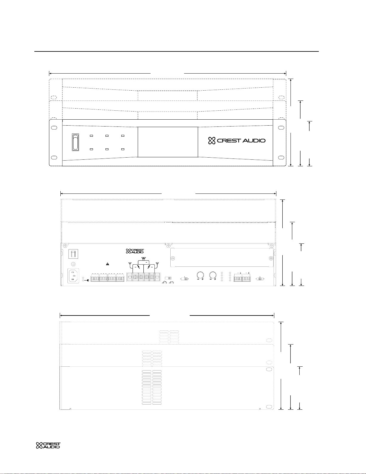
CKi Power Processing amplifiers are 2,3 & 4-rack space units of 17 1/8" (437mm)
depth that mount in a standard 19-inch rack.On 2 &3 rack space units,four front
panel-mounting holes are provided.4-rack space units have eight front panel-mounting holes.
Rear mounting ears are also provided on all amplifiers for additional support,which
is essential in non-permanent installations like mobile or touring sound systems,and
recommended for permanent installations.(Distance from the back of the front rack
ear to the center of the rear mounting ear holes is 16 5/8" / 422mm) Because of the
cables and connectors on the rear panel,a right-angle or offset screwdriver or hex
key will make it easier to fasten the rear mounting ears to the rails
For replacement
packaging,call Crest
Audio’s Customer Service
Department directly.
see—service and support
+
Page 9
p.5
Installation
2
Protect
Active Signal
ACL
Status Ch BCh A
Signal
ACL
Remote
Off
On
CKi 100s Professional Power Amplifier
19” (483mm)
3.5” (89mm)
5.25” (133mm)
7” (178mm)
Front View
17” (432mm)
3.5” (89mm)
5.25” (133mm)
7” (178mm)
IGM
Protect
AB
ACL
Signal
Ch BCh A
Input
+
Gain
(.775V)
0dB
x40x20
+
Mode
Stereo
ParallelBridge
Active
+
AB
A B
+
+
Output - Class 2 Wiring
In Out
On
Com
Off
On
Com
Off
Fault
N/O
Com
N/C
Gnd
In
Sequential Turn-On
Input
V-In
Crest Audio, Inc.
Fair Lawn, NJ USA
www.crestaudio.com
Designed and manufactured in the USA by:
3.3V
Out
Ch B
-30
-6
-1
dB
Ch A
-3
-10
-15
-
-30
-6
-1
dB
-3
-10
-15
-
Rear View
17.1” (435mm)
3.5” (89mm)
5.25” (133mm)
7” (178mm)
Side View
Page 10

p.6
Installation
2
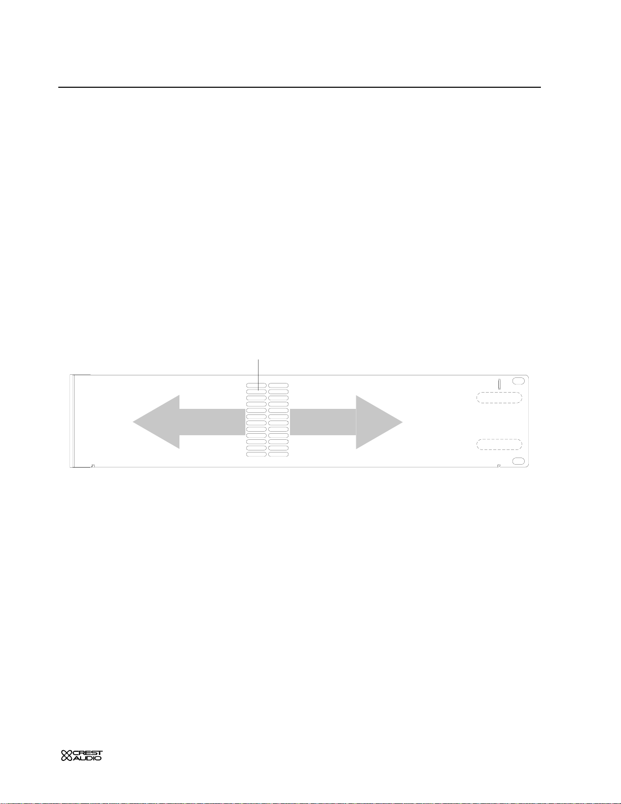
Cooling Requirements
CKi amplifiers use a forced-air cooling system to maintain a low,even operating temperature.Air drawn by a fan mounted behind the front panel enters through the front grille and
the heated air exits through the side panel ports.On two an three space CKi amplifiers the
fan will remain inactive until operating temperature rises to 45° C.One four space units the
fan runs all the time.Make sure that there is enough space around the front of the amplifier
to allow air to enter, and around the sides to allow the heated air to exit. System cooling
needs must be considered before installation,and the system installer/designer should specify
appropriate countermeasures,such as ventilation,air conditioning,etc.Refer to Appendix A
for specific thermal emission figures.
Note:If the amplifier is rack-mounted,do not use doors or covers on the front or rear
without pressurizing the rack.Make sure that heated air can escape freely, and that there is
no resistance to the intake of cool air.Intake and exhaust air must flow without restriction.
Fan filters should be regularly cleaned and periodicall y replaced.
Circuit Size Requirements
CKi amplifier power requirements are rated at “idle, ” 1/8th power (“typical” music condi-
tions),1/3rd power, and maximum rated power.The maximum power current draw rating is
limited by the amplifier's circuit breaker. Consult Appendix A for the current that each amplifier model will demand.AC mains voltage must be the same as that indicated on the rear of
the amplifier. Damage caused by connecting the amplifier to improper AC voltage is not covered by any war ranty.
PowerSave
All CKi amplifiers come standard with PowerSave circuitry.This effectively r educes current
draw and thermal emissions to a minimum when the amplifier is at idle.PowerSav e operates
by cutting off the bias current to the output stage after absence of signal is sensed at the
input.When signal presents itself,PowerSave instantly restores the bias curr ent after the first
positive-going waveform.Current draw specifications while PowerSa ve is active are included
in specifications under "Idle Current Draw."
Maintenance
CKi amplifiers require little routine maintenance.
When used in an extremely dusty or smoky en vironment,the unit should be periodically
blown free (using compressed air) of any foreign matter that may have built up inside.
When used in an environment where residue from smoke/fog machines is regularly present,
the amplifier(s) should be periodically checked (by authorized Crest service personnel) for
build-up of that residue.
The filter in the front panel air intake grille should be periodically cleaned. Should the filter
become permanently clogged or damaged,a replacement should be obtained through your
Crest representative
Users will not need to make an y adjustments to the amplifier during its lifetime.Other than
installing or replacing a NexSys module,there are no user-serviceable parts or adjustments
that require opening the unit.
Always turn off and
disconnect the
amplifier from the mains
voltage before making
audio connections.If
possible, as an extra precaution,have the attenuators turned down during power-up.
+
Page 11

p.7
Features Overview
3
Front Panel
Side Panel
Rear Panel
/
Controls and connectors
/
Legend of panel symbols
/
Air flow
Page 12
p.8
Features Overview
3
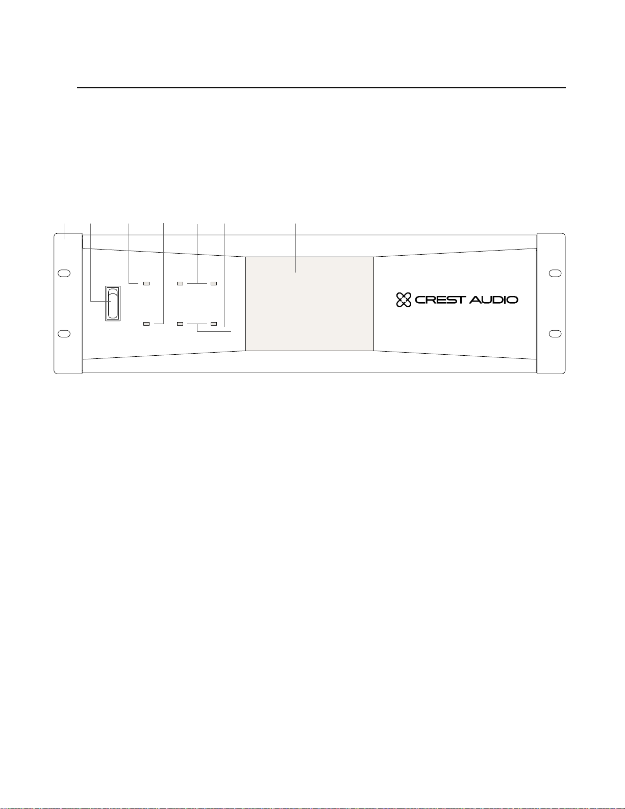
Front Panel
1
Rack Mounting Ears
Two holes (four on 4U amplifiers) are provided on each front mounting ear..
2
3-Position Power Switch
With this switch in the “up” position the amplifier is On. The middle
position is Off and the lower position is marked Remote. When
switched to Remote,the amplifier must be activated by the sequential
turn on/turn off (STO) circuit.
3
Protect LED
If the amplifier enters any of its Protect modes,the output relay will
open,and this LED will light.
4
Active LED
The Active LED indicates the amplifier is turned on and the output
relays have closed.
5
ACL LEDs
Each channel has an ACL (Active Clip Limiting) LED. If a channel reaches the clipping point,this LED will light to show that the ACL circuit is
active.
Front Panel - CKi 800s shown
1 2 3 4
7
5
6
This chapter identifies the switches,indicators,connectors and functional components of all CKi amplifiers.Keep in mind that this chapter is only as an
overview of the amplifier’s layout,and does not contain all the information nec-
essary to effectively operate the CKi. For more detailed information on the
items listed here,be sure to read this entire manual.
On
Off
Remote
Protect
Status Ch BCh A
Active Signal
ACL
ACL
Signal
CKi 800s Professional Power Amplifier
Page 13
p.9
Features Overview
3
1
Warm Air
Warm Air
Front Panel cont.
6
Signal LEDs
Each channel has a Signal LED .The intensity of the light varies with signal level – the stronger the input signal,the brighter the LED.
7
Fan Grille & Filter
A DC fan draws air into the amplifier though the removable dust filter. Do not block this intake! The fan operates only when the amplifier requires cooling. Fan filters are easy to remove and should be
cleaned regularly to ensure optimum performance. Contact your
Crest Representative to obtain replacement filters.
Side Panel
1
Exhaust Ports
Heated air exits through the exhaust ports,on the sides of the amplifier chassis.Do not block these ports.
Side View
Page 14
p.10
Features Overview
3
Never connect a hot
(red) output to ground
or to another hot (red)
output!
a
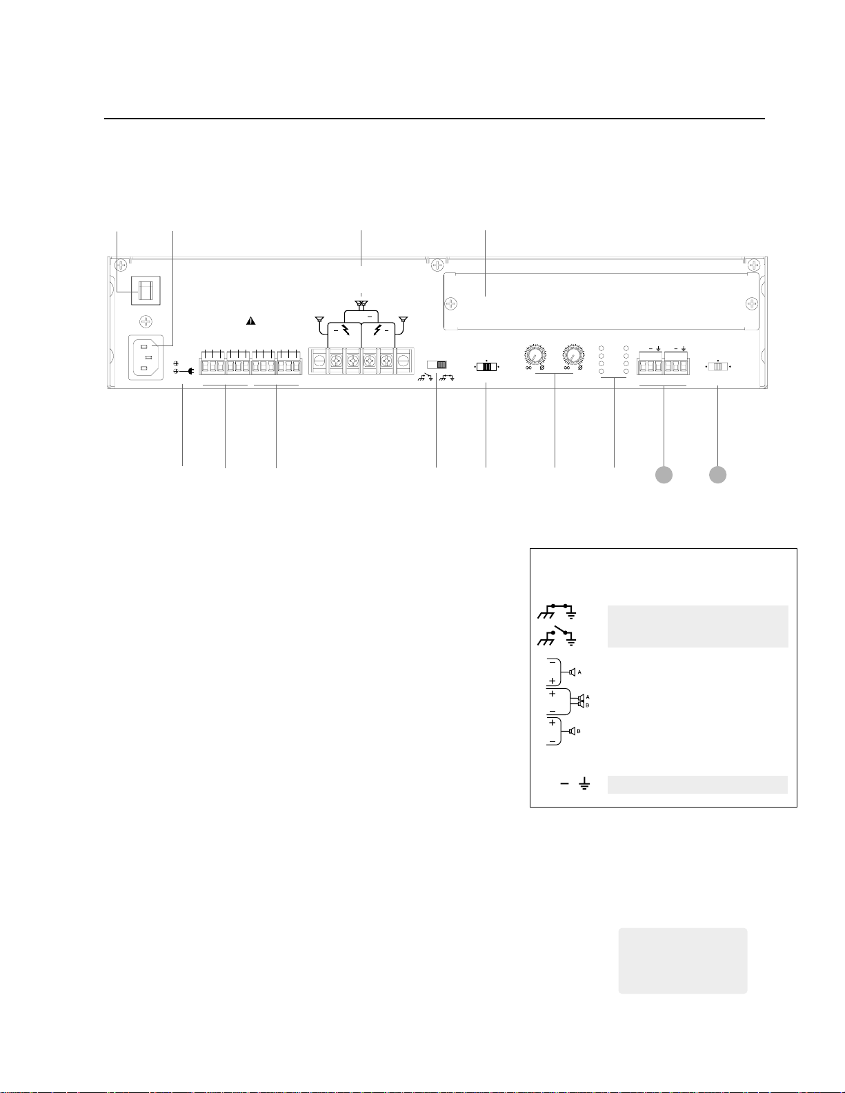
Rear Panel
1
Mains Breaker
2U & 3U amplifiers hav e a push-type circuit br eak er,while 4U units have
a throw-switch style breaker. If the unit’s breaker trips repeatedly, the
amplifier needs servicing.
2
IEC Power Cord Connector
On 2U amplifiers, a standard IEC power connector is located on the
rear panel of amplifier . The connector accommodates a standard IEC line
cord, included in the amplifier box. Should this cord need to be
replaced,only a cord with the same current rating should be used.3U
& 4U units have a captive power cord.
3
AC Mains / Active LED indicators
The AC mains yellow LED indicates that the amplifier is attached to a
power source.The activ e green LED indicates that the amplifier has been
turned on and is operating.
4
Sequential turn on/off Connectors
These connectors can be wired to a contact closure for remote turnon and to other CKi amplifiers for sequential turn-on (STO).
5
Fault I/O Connector
This output is a contact closure that can be used to report a fault condition (e.g.an open output relay) in the amplifier.
Rear Panel Legend
Ground Connected
Ground Lifted
Channel A stereo/parallel
Bridged mono
Channel B stereo/parallel
Input Polarity
3
Rear Panel - CKi 100s shown
2
¡09
8
6
1
4
5
7
12
13
Active
Sequential Turn-On
On
On
Off
Com
Com
In Out
Designed and manufactured in the USA by:
AB
Fault
V-In
N/C
N/O
Off
3.3V
In
Input
Com
Gnd
Out
Crest Audio, Inc.
Fair Lawn, NJ USA
www.crestaudio.com
A B
+
+
+
Output - Class 2 Wiring
Stereo
Mode
-6
-10
-15
-15
-3
-1
-30
ParallelBridge
-30
-
dB
Ch A
AB
-6
-10
-
Ch B
Protect
-3
IGM
-1
ACL
dB
Signal
Ch BCh A
+
+
Input
(.775V)
0dB
Gain
x40x20
+
Page 15

p.11
Features Overview
3
Rear Panel cont.
6
Output Connectors
A barrier strip provides output connection terminals for two speakers operating in stereo or parallel, for a single speaker wired in a
bridged mono configuration,or for constant voltage distribution.Bare
wire or spade lugs may be used to make barrier strip connections.
7
Ground Lift Switch
This switch disconnects the audio ground from the chassis ground in
the amplifier.
8
Module Bay
All CKi amplifiers possess a module bay configured to accept interchangeable plug-in modules. Your amplifier may have been factory
configured with a module. Information on all CKi modules is available
in this manual.
See – Chapter 7 NexSys Modules for more information.
9
Mode Select Switch
This switch reconfigures the amplifiers outputs f or ster eo,parallel,or
bridged operation..
0
Input Attenuators
Each channel has an attenuator knob to adjust the channel’s output
from -∞ to maximum power.
¡
Status LEDs
The “Protect,” “Signal, ” and “ACL” LED’s on the rear panel serve the
same function as the front panel LED’s of the same names.The “IGM”
LED will light if the amplifier’s IGM protection circuit engages.
Input Connectors
The CKi uses one 3-pin Phoenix connector per channel for balanced
line-level audio input. These inputs can also be setup to accept an
unbalanced signal.
Gain (input sensitivity) Select Switch
This switch sets the amplifier’s gain structure as constant sensitivity
(0dB setting) or constant gain (x20 or x40 settings).
Do not adjust the
mode selection switch
while the amplifier is
turned-on.
a
In situations where an
UNBALANCED signal is fed to the amp,
it’s important to ground
the unused input.If the
inverting (-) input of an
amp channel is left floating,the gain will drop
by 3 dB.
+
12
13
Page 16

Page 17

p.13
Modes
4
Stereo
Parallel
Bridged
Constant
Voltage
/
Choosing the appropriate mode
/
Switching between operation modes
/
Special considerations when using bridged mode
/
Connecting to a constant voltage Line
Page 18

p.14
Modes
4
Mode Selection
The rear panel Mode Select Switch determines whether the amplifier is in
stereo,parallel or bridged mono mode. Do not operate the Mode Select
Switch with the amplifier on.See the next chapter on Operation for proper
wiring in each mode.
Stereo
For stereo (dual channel) operation,turn the amplifier off and set the Mode
Select Switch to the stereo position.In this mode,both channels operate independently of each other, with the input attenuators controlling each channel’s
level. Thus, a signal at Channel A’s input produces an amplified signal at Channel
A’s output,and the same for Channel B.
Parallel
For parallel (dual-channel/single input) operation,turn the amplifier off and set
the Mode Select Switch to the parallel position;both amplifier channels will
now be driven by the signal at Channel A’s input. No jumper wires are needed.
Output connections are the same as in the stereo mode. In the parallel mode,
only Channel A’s input is active;Channel B’s input is not in the circuit.Both
attenuators remain active,permitting different levels for each channel.Power
and other performance specifications are the same as in the stereo mode.
Bridged Mono
For Bridged (single channel/single input) operation,turn the amplifier off and
set the Mode Select Switch to the Bridge position. This Mode straps both
amplifier channels together, making a very powerful single channel.One channel
“pushes” and the other “pulls” equally,effectively quadrupling the power of
either channel alone.As in Parallel mode,signal is connected to Channel A. The
nature of Bridged mode requires that both attenuators be set at the same
level,preferably at 0dB attenuation.The speakers are connected only to the
designated “+” output terminals. Use extreme caution when operating in the
bridged mode,as potentially lethal voltage may be present at the output terminals.
Unlike the stereo and parallel modes,in which one side of each output is
grounded,both sides are hot in bridged mono mode. Channel A’s side is the
same polarity as the input.Never ground either side of the speaker cable when
the amplifier is in bridged mono mode;both sides are “hot. ” If an output patch
panel is used,all connections must be isolated from each other and from the
panel.
Constant Voltage
CKi-V and CKi-X Series amplifiers are designed for use with distributed or
constant voltage systems. These amplifiers can also be wired for Bridged Mono
mode operation,however,bridging these models is usually undesirable, as the
output will be approximately 140V (CKi-V) or 200V (CKi-X) There are,however,specific applications for this configuration.Contact Crest Audio Customer
Service for more information if required.
See – Appendix B for information on recommended distributed line impedance.
Connecting amplifier
outputs to oscilloscopes or other test
equipment while the
amplifier is in bridged
mode may damage both
the amplifier and test
equipment!
a
Regardless of operating
mode, NEVER connect amplifier outputs
directly together!
a
Mode
Stereo
ParallelBridge
-3
-15
Page 19

p.15
Operation
5
Power
Input
Output
STO
/
Connecting the amplifier to AC power
/
Proper signal paths
/
Proper wiring schemes for output connectors
/
Sequential turn on/off
/
Additional operation considerations
Page 20

p.16
Operation
5
Operation
Inputs
All CKi series amplifiers use 3-Pin Phoenix connectors for attaching input signals. Each connector is configured (from left to right) positive,negative,
ground.
Input Phoenix Connectors
Outputs
Direct
Direct (speaker) outputs ar e connected to CKi series amplifiers via the
rear-panel terminal strips. Be sure to properly calculate the total
impedance of all speakers connected to a direct output and to not
exceed the minimum impedance rating of your CKi amplifier
Constant V oltage
For CKi-v and CKi-x models constant voltage (distributed) lines are
connected to via the same rear-panel terminal strips. Be sure to properly calculate the total wattage demand of each constant voltage line
and to not exceed the maximum output rating of your CKi amplifier.
Output Barrier Strip
See — the wiring diagrams on the next two pages for more information on
connecting your CKi amplifier.
Power
Unless otherwise specified when ordered,CKi Series amplifiers are shipped
from the factory set to one of following voltage options:
Option 1 US domestic
Nominal 120Vac 60Hz for rated power output (safe operating range
100 - 132V ac )
Option 2 Export
Nominal 230Vac 50Hz for rated power output (safe operating range
200 - 264V ac )
Very high current is
available at the outputs.
Please connect your
output cable to the +
and - terminals of each
section precisely as
shown.
a
In situations where an
UNBALANCED signal is fed to the amp,
it’s important to ground
the unused input.If the
inverting (-) input of an
amp channel is left floating,the gain will drop
by 3 dB.
+
Ch BCh A
+ +
A B
AB
+
+
+
Page 21

p.17
Operation
5
Stereo Mode
Direct Outputs
Parallel Mode
Direct Outputs
Bridged Mono Mode
Direct Outputs
Active
A
Active
Sequential Turn-On
On
On
Off
Com
Com
In Out
Sequential Turn-On
On
On
Off
Com
Com
In Out
Designed and manufactured in the USA by:
AB
Fault
V-In
N/C
N/O
Off
Gnd
Input
3.3V
Com
In
Out
Crest Audio, Inc.
Fair Lawn, NJ USA
www.crestaudio.com
A B
+
+
+
Output - Class 2 Wiring
Nx Ethernet
Edit FunctionSelect
Stereo
Mode
Ethernet
(.775V)
0dB
Gain
Data
Link
x40x20
I.P. Address
Amp ID
Gain
AB
Ch B
-6
-3
-1
dB
Fault
Mute
AB
Protect
IGM
ACL
Signal
Ch BCh A
+
+
Input
Temperature
AC Voltage
-6
-10
-10
-15
-15
-3
-1
-30
ParallelBridge
-30
-
-
dB
Ch A
Ch. B
+
(.775V)
0dB
Gain
Ch. A
+
Data
Link
x40x20
B
Designed and manufactured in the USA by:
AB
Fault
V-In
N/C
N/O
Off
Gnd
Input
3.3V
Com
In
Out
Crest Audio, Inc.
Fair Lawn, NJ USA
www.crestaudio.com
A B
+
+
+
Output - Class 2 Wiring
Nx Ethernet
Edit FunctionSelect
Stereo
Mode
I.P. Address
Amp ID
Gain
AB
-
Ch B
-6
-3
-1
dB
Fault
Mute
AB
Protect
IGM
ACL
Signal
+
Input
Temperature
AC Voltage
-6
-10
-10
-15
-15
-3
-1
-30
ParallelBridge
-30
-
dB
Ch A
Ethernet
Ch BCh A
+
A
Sequential Turn-On
On
On
Off
Off
Com
Com
Active
In Out
3.3V
B
Ch. A
+
Designed and manufactured in the USA by:
AB
Fault
V-In
N/C
N/O
Gnd
Input
Com
In
Out
Crest Audio, Inc.
Fair Lawn, NJ USA
www.crestaudio.com
A B
+
+
+
Output - Class 2 Wiring
Nx Ethernet
Edit FunctionSelect
Stereo
Mode
Ethernet
(.775V)
0dB
Gain
Data
Link
x40x20
I.P. Address
Amp ID
Gain
AB
Temperature
AC Voltage
-6
-10
-10
-15
-15
-3
-1
-30
ParallelBridge
-30
-
dB
Ch A
Fault
Mute
AB
-6
Protect
-3
IGM
-1
Ch B
ACL
dB
Signal
-
Ch BCh A
+
+
Input
Ch. A
+
Bridged
Page 22

p.18
Operation
5
Stereo Mode
Constant Voltage Output (V & X Models only)
Parallel Mode
Constant Voltage Output (v & x Models only)
Removable Attenuator Knobs
The attenuator knobs can be removed and replaced with plugs that are
shipped with the amplifier.The procedure for attenuator knob removal is as follows:
1. With a small knife, remove the gray key cap of the attenuator knob
revealing the inside nut.
2.Using needle nose pliers or an appropriately sized nut driver,loosen
the nut.
3.Slide the attenuator knob off the shaft.
4.Insert a regular screwdriver in the slotted end of the shaft and adjust
attenuation to the desired level.
5.Insert the blank plugs into the attenuator holes.
llel
Ch B
-30
-6
-1
dB
Ch A
-3
-10
-15
-
-30
-6
-1
dB
-3
-10
-15
-
Ch.A - Knob still attached
Ch.B - Knob replaced with plug
Designed and manufactured in the USA by:
AB
+
+
Output - Class 2 Wiring
Active
Sequential Turn-On
On
On
Off
Com
Com
In Out
Fault
V-In
N/C
N/O
Off
Gnd
Input
3.3V
Com
In
Out
CV Line Ch. A
Designed and manufactured in the USA by:
AB
+
+
Output - Class 2 Wiring
Active
Sequential Turn-On
On
On
Off
Com
Com
In Out
V-In
Off
3.3V
In
Fault
N/C
N/O
Gnd
Input
Com
Out
CV Line Ch. A
Crest Audio, Inc.
Fair Lawn, NJ USA
www.crestaudio.com
A B
+
Crest Audio, Inc.
Fair Lawn, NJ USA
www.crestaudio.com
A B
+
CV Line Ch. B
CV Line Ch. B
Nx Ethernet
Edit FunctionSelect
Stereo
Mode
Nx Ethernet
Edit FunctionSelect
Stereo
Mode
Ethernet
(.775V)
Gain
Data
Link
0dB
x40x20
I.P. Address
Amp ID
Gain
AB
Fault
Temperature
Mute
AC Voltage
-6
-10
-15
-1
-30
ParallelBridge
-
dB
Ch A
AB
-6
-10
Protect
-15
-3
-3
IGM
-1
-30
ACL
-
dB
Signal
Ch B
Ch BCh A
+
+
Input
Ch. B
+
Ch. A
+
Ethernet
(.775V)
Gain
Data
Link
0dB
x40x20
I.P. Address
Amp ID
Gain
AB
Fault
Temperature
Mute
AC Voltage
-6
-10
-15
-1
-30
ParallelBridge
-
dB
Ch A
AB
-6
-10
Protect
-15
-3
-3
IGM
-1
-30
ACL
-
dB
Signal
Ch B
Ch BCh A
+
+
Input
Ch. A
+
Page 23

p.19
Operation
5
Gain Select Switch
The 3-position gain select switch on the rear panel to sets the overall gain of
the amplifier.The left and right switch positions set the amplifier for constant
gain of x20 (26 dB) or x40 (32 dB) respectively .The center position sets the
amplifier for constant sensitivity. In this position,a 0dBu (0.775 VRMS) input
signal will produce maximum power at the amplifier’s output.The standard
factory setting is for x40 (32dB).The specifications for a specific CKi models
in Appendix A contain more gain/sensitivity information.
Signal Ground Lift Switch
The signal source equipment should share the same AC ground as the amplifier(s).In some cases,however, particularly if an amplifier is being installed in
an existing system,this may result in a gr ound loop, creating excessive 60Hz
hum at the amplifier’s output.If this happens,slide the ground lift switch on
the amplifier’s rear panel to the “open” (left) position.In this position,the sig-
nal ground is lifted from the chassis ground and is clamped to ± 0.6V. Do not
lift the ground if the amplifier and the signal source equipment are not on the
same AC ground! In a properly designed system,the amplifier should receive
its ground from the AC line cord to ensure safety and minimize noise.
Sequential Turn On/Off (STO)
CKi amplifiers come standard with Sequential Turn-On/Turn-Off (STO) circuitry.When the amplifier front power switch is set to “remote, ” a single
SPDT toggle switch or two SPST momentary switches can be used to turn
the amplifier on and off.Using the same switch(es),additional amplifiers can
be turned on/off sequentially by daisy chaining the STO "Out" terminals of
one amplifier to the STO "In" terminals of a subsequent amplifier.The standard turn-on delay time between amplifiers is approximately 100ms;turn-off
delay time is 200ms. When using NexSys control with an amplifier equipped
with an NxEthernet or NxCobraNet module,these standard turn-on and
turn-off delay times may be modified in the control software.
Standard Sequential Turn-On/Turn-Off Wiring
For non-NexSys remote turn-on,a single SPDT toggle switch or two SPST
momentary switches can be used.In either case, the switch(es) are wired to
the “STO In” connector on the amplifier’s rear panel and the amplifier’s front
panel power switch must be set to “Remote.” The switch(es) should be wired
to close a connection between “Com” and “On” pins for turn-on,and
between the “Com” and “Off” pins for turn-off. The diagram below illus-
trates the circuit:
The shield on a balanced input line should
be grounded at one end
only (usually the sending
end),and it must never
be relied on to supply
AC ground to the amplifier.
a
When using NexSys
control,hardwiring
for manual switch
closure between amplifiers should be used cautiously. If the switch closure output is wired up,
it WILL cause the next
amp to switch,regardless of which source
(hardware switch or
NexSys STO command)
has initiated the command.
+
g
g
(.775V)
0dB
x40x20
Gain
On
Off
Sequential Turn-On
Sequential Turn-On
Active
Active
On
On
Off
Off
Com
Com
In Out
In Out
Fault
V-In
Fault
V-In
N/C
N/C
N/O
3.3V
3.3V
Input
Input
In
In
Gnd
Gnd
N/O
Out
Out
Com
Com
On
On
Off
Off
Com
Com
+ +
+ +
Output - Class 2 Wirin
Output - Class 2 Wirin
Page 24

p.20
Operation
5
ST O Daisy Chaining
Any number of CKi amplifiers can be daisy-chained together for
sequential turn-on. Wiring two amplifiers for STO is as simple as connecting the “On, ” “Com” and “Off” pins of the “STO Out” connector
on the first amplifier to the corresponding pins on the “STO In” con-
nector on the second amplifier.Repeating this wiring scheme with subsequent amplifiers allows entire systems of CKi’s to be wired for STO.
Modules
CKi amplifiers come standard with a blank panel fixed over the module bay.
When a NexSys module is installed in this bay,connection to a network is
made via a standard RJ-45 connector and CAT-5 Ethernet cable.
Module Removal/Installation
The amplifier must be switched off and unplugged from the AC mains
supply before any module operation is undertaken. Two Phillips head
screws secure the module/panel to the chassis.The module is connected electrically to the amplifier with a single multi-pin ribbon cable.Once
unscrewed from the chassis, unplugging the module from this ribbon
cable frees the module for removal. To insert a module, simply reverse
this procedure.
See – Chapter 7 NexSys Modules for more information
Module Bay with Blank Panel Installed
Module Bay with Nx Ethernet Module Installed
W
A
a
c
W
A
a
c
Standard CKi Power
Processing amplifiers
come with a blank panel
installed in the Network
bay.The amplifier must
not be operated without
a Network module or
blank panel in place.
a
Removable modules
contain static-sensitive
devices;handle modules
only at static-safe workstations!
a
N
N
Designed and manufactured in the USA by:
Fault
/O
N/C
Com
Out
Crest Audio, Inc.
Fair Lawn, NJ USA
www.crestaudio.com
A B
AB
+
+
+
Output - Class 2 Wiring
Stereo
Mode
-6
-10
-15
-1
-30
ParallelBridge
-
dB
Ch A
AB
-6
-10
Protect
-15
-3
-3
IGM
-1
-30
ACL
-
dB
Signal
Ch B
Ch BCh A
+
+
(.775V)
0dB
Input
x40x20
Gain
Designed and manufactured i
Sequential Turn-On
On
Off
Com
Active
In Out
Sequential Turn-On
On
Off
Com
Active
In Out
On
Off
Fault
V-In
N/C
N/O
On
Off
Gnd
Input
3.3V
Com
Com
In
Out
Designed and manufactured i
Fault
V-In
N/C
N/O
On
Off
Gnd
Input
3.3V
Com
Com
In
Out
A
Output - Class 2
A
Output - Class 2
Crest
Fair L
www.
A B
+
+
+
Crest
Fair L
www.
A B
+
+
+
Designed and manufactured in the USA by:
Fault
/O
N/C
Com
Out
Crest Audio, Inc.
Fair Lawn, NJ USA
www.crestaudio.com
A B
AB
+
+
+
Output - Class 2 Wiring
Nx Ethernet
Edit FunctionSelect
Stereo
Mode
Ethernet
(.775V)
0dB
Gain
Data
Link
x40x20
I.P. Address
Amp ID
Gain
AB
Fault
Temperature
Mute
AC Voltage
-6
-10
-15
-1
-30
ParallelBridge
-
dB
Ch A
AB
-6
-10
Protect
-15
-3
-3
IGM
-1
-30
ACL
-
dB
Signal
Ch B
Ch BCh A
+
+
Input
Page 25

p.21
Safety
6
User
Responsibility
Speaker
Protection
Protection
Features
/
The owner’s role in amplifier safety
/
Protecting your speakers
/
Description of protection features
Page 26

p.22
Safety
6
Speaker Protection
All loudspeakers have electrical,thermal and physical limits which must be
observed to prevent damage or failure. Too much power, severely clipped wave
forms,low frequencies applied to high frequency drivers and DC voltage can all
be fatal to cone and compression drivers. Crest Audio CKi Series amplifiers
automatically protect speakers from DC voltages and subsonic signals.
Be sure that the low and mid bands of an electronic crossover are connected
to the correct amplifiers and driv ers,and not accidentally connected to those
for a higher frequency band. The amplifier’s clipping point is its maximum peak
output power,and some of the higher-powered CKi Series amplifiers can deliver more power than many speakers can safely handle.Be sure the peak power
capability of the amplifier is not excessive for your speaker system.
To ensure the speakers never receive excessive power and that the amplifier
never clips,use a properly adjusted external limiter (or a compressor with a
ratio of 10:1 or higher) to control power output;in systems with active electronic crossovers,use one for each frequency band. The clip limiter will automatically limit the duration of squared-off,continuous wave forms applied to
the speakers.The amplifier will,however,allow normal musical transient bursts
to pass. When the amplifier does clip,it is at its maximum output power.
Some speaker systems are packaged with processors that have power limiting
circuits and should not require additional external limiting. Fuses may also be
used to limit power to speaker drivers,although as current-limiting rather than
voltage limiting devices. Some poor quality fuses have a significant series resistance that could degrade the amplifier’s damping of the speaker’s motion and
may even deteriorate the system’s sound quality. If you elect to use fuses,
check with the speaker manufacturer to determine the proper current rating
and time lag required.
Do not drive any low frequency speaker enclosure with frequencies lower than
its own tuned frequency;the reduced acoustical damping could cause a ported
speaker to bottom out even at moderate power. Consult the speaker system
specifications to determine its frequency limits.
The wire gauge charts in Appendix D will assist you in determining the optimum copper wire gauge for speaker cables in direct output systems.Speaker
cable resistance robs amplifier power in two ways:through power lost directly
to resistance (often referred to as I2R loss),and through increased total load
resistance,which decreases the amount of power available from the amplifier.
Appendix D gives cable length figures in feet/AWG wire gauges and in metric
values.
User Responsibility
Your CKi Series amplifier is very powerful and can be potentially dangerous to
loudspeakers and operators alike.It is your responsibility to read all precautions and make sure that the amplifier is installed,wired,and operated properly
as instructed in this manual.
Many loudspeakers can be easily damaged or destroyed by overpowering,especially with the high power available from a bridged amplifier. Always be aware
of the speaker’s continuous and peak power capabilities.Crest Audio is not
responsible for damage to loudspeakers for any reason.
Page 27

p.23
Safety
6
Protection Features
CKi Series amplifiers incorporate several circuits to protect both themselves
and loudspeakers. Crest Audio has attempted to make the amplifiers as foolproof as possible by making them immune to short and open circuits,mismatched loads,DC voltage and overheating. If a channel goes into ACL gain
reduction mode,the speaker load will remain connected but clipping percentage or output power will be instantly reduced. When a problem occurs that
causes a channel to go into a protection mode,the Protect LED for that
channel will glow. DC voltage on the output,excessive subsonic frequencies
or thermal overload will cause the channel’s output rela y to open,discon-
necting the speaker load until the condition is corrected.
Automatic Clip Limiting (ACL)
Any time a channel is driven into continuous clipping,the clip limiter
circuit will reduce the channel gain to a le v el just slightly into clipping,
which protects the speak ers against the damaging,high power,continuous square wav es. Situations that may activate the clip limiter include
uncontrolled feedback, oscillations, and improper equipment setting
or a malfunction upstream from the amplifier. Normal pr ogram transients will not trigger the clip limiter; only steady,excessive clipping
will. The ACL LED will glow brightly and continuously when limiting
occurs.
IGM Impedance Sensing
CKi Series amplifiers feature innovativ e circuitry that allows safe operation into any load. When an amplifier sees a load that overstresses
the output stage, the Instantaneous Gain Modulation (IGM) circuit
adjusts the channel gain to a safe level. This method of output stage
protection is far superior to the conventional,brute force-type limiting found on other amplifiers. The IGM circuit is sonically transpar ent
in normal use and unobtrusive when activated.
Thermal Protection
The internal fan will keep the amplifier operating well within its
intended temperature range under normal conditions.If a channel’s
heat sink temperature reaches 75°C (which may indicate an obstruct-
ed air supply),that channel will independently protect itself by disconnecting its load and shutting down until it has cooled. During this
time,the Protect LED will light,the Activ e LED will extinguish and the
cooling fan will run at its highest speed.
Short Circuit
If an output is shorted,the IGM and thermal circuits will automatically protect the amplifier. The IGM circuit senses the short circuit as an
extremely stressful load condition and attenuates the signal,protecting the channel’s output transistors from over-current stress. If the
short circuit remains, the channel will eventually thermally protect
itself by disconnecting the load.
DC V oltage Protection
If an amplifier channel detects DC voltage or subsonic frequencies at
a channel output,the respective output rela y will immediately open to
prevent loudspeaker damage.The Protect DC LED will light.
Page 28

p.24
Safety
6
p.24
Safety
6
Turn-On/Turn-Off Protection
At power-up,the amplifier stays in the protect mode with outputs disconnected for about six seconds,while the power supplies charge and
stabilize.While the output relays are open, the ACL LEDs will light.
When the power is turned off,the speaker loads immediately disconnect so that no thumps or pops are heard.
Auto Ramp Signal Control
Whenever a CKi Series amplifier pow ers up or comes out of a pr otect
mode,the Auto Ramp circuit activates. While the speakers are disconnected,the Auto Ramp circuit fully attenuates the signal. After the output rela y closes,the signal slowly and gradually raises up to its set level.
P o w erSa ve
All CKi amplifiers come standard with PowerSave circuitrywhich
reduces current draw and thermal emissions at idle. PowerSave operates by cutting off the bias current to the output stage when signal is no
longer sensed at the input.When signal appears,bias current is instantl;y
restored after the first positive-going waveform. Current draw specifications while PowerSave is active are included in specifications under
"Idle Current Draw."
NexSys Fault Monitoring
A CKi equipped with an NxEthernet or NxCobraNet module and connected to a NexSys network will report fault conditions to the PC controlling the network. If a networked amplifier enters ACL or IGM or
experiences a thermal,DC voltage, or short circuit fault,the fault condition will be reported the PC interface.This allows easy monitoring of
amplifier operating conditions across a large or widespread network
from a single location.
Page 29

p.25
NexSys Modules
7
Overview
Installation
Features
Operation
Amplifier ID
Condition
Monitoring
/
General module information
/
Installing a module
/
Individual module features
/
Using a module
/
Setting amplifier IDs
/
Amplifier monitoring via modules
Page 30

p.26
NexSys Modules
7
Overview
The extended capabilities of CKi amplifiers are reached when connected to a
NexSys amplifier network via a NexSys module.These modules reside in the
CKi’s module bay and provide control,monitoring, and signal processing fea-
tures.This chapter covers the installation of NexSys modules as well as information concerning computer control of a NexSys system.For more information about controlling a system with NexSys r efer to the NexSys System
Manual
Module Installation
There are tw o modules through which a CKi amplifier can be connected to a
NexSys network – the NxEthernet Module and NxCobranet Module.
Although they have different feature sets,they both serve the networking function. Because of this,they are collectively ref erred to as “network modules.”
The installation procedure for both is the same.
1.Remove the blank panel covering the CKi’s module bay by removing
the screws on either side of the panel.Save these scr ews,as they will be
needed for fastening the network module.
2.Inside the exposed module bay you should see the ribbon cable con nector on the amplifier’s circuit board.Note of the way the connector
is keyed, and position the ribbon cable to match.Inser t the cable into
the connector, with the opposite end hanging out of the module bay.
3.Position the network module right side up.Connect the exposed end
of the ribbon cable to the connector on the module,again taking note
of the keying of the connectors.
4.Slide the module into the bay,and fasten it to the CKi’s chassis with
the screws removed in Step #1.
Active
Sequential Turn-On
On
On
Off
Com
Com
In Out
Designed and manufactured in the USA by:
AB
Fault
V-In
N/C
N/O
Off
Gnd
Input
3.3V
Com
In
Out
Crest Audio, Inc.
Fair Lawn, NJ USA
www.crestaudio.com
A B
+
+
+
Output - Class 2 Wiring
Stereo
Mode
-6
-10
-15
-30
ParallelBridge
-
Ch A
AB
-6
-10
-15
-3
-1
-30
dB
Protect
-3
IGM
-1
ACL
-
dB
Signal
Ch B
Ch BCh A
+
+
(.775V)
0dB
x40x20
Input
Gain
Nx Ethernet
Edit FunctionSelect
I.P. Address
Amp ID
Gain
Temperature
AC Voltage
AB
Fault
Mute
Ethernet
Data
Link
Page 31

p.27
NexSys Modules
7
Module Features
This following pages describe the buttons,indicators,connectors and functional components that are relevant to the two NexSys modules. These features exist on both the NxEthernet and NxCobranet Modules. Features
specific to the NxCobranet Module are discussed later in this chapter.
1 4-character Displa y
The LED display shows the value of the current parameter for the
function chosen. The selected Function is indicated by the corresponding LED.
2 Edit Button
Enables and disables editing of a function parameter. When pressed,
the value in the display will flash,indicating that edit mode has been
entered.The value can now be adjusted using the incrementand decre-
ment buttons.Pressing Edit again will register the value and stop the
flashing of the display.
3 Select Button
When a function parameter exists for both channels independently
(e.g.Gain,Temperature),this button changes between the parameter
values for Channel A and Channel B.This button is also used to select
parameters within a given function.
4 Function Button
This button scrolls through the functions that can be controlled from
the module panel including: I.P.Address,Amp ID,Gain,Temperature,
AC Line Voltage. As each is selected,the corresponding LED wil light
and the appropriate function parameter will a ppear in the display.
5 Increment/Decrement Buttons
When the module is in edit mode and the value in the displa y is flashing,the increment and decrement buttons will adjust the value.
6 Function LEDs
Each of the main functions has a corresponding LED. When a function is selected,this LED will light to identify the selection.Some secondary functions do not have an associated LED,so no LED will light
when these functions are selected.
1 2 3 4 5 6 7 8 9 0
¡
Not all function parameters can be adjusted (e.g.AC Line
Voltage,Temperature,
etc.) as they are output
values only.
+
Nx Ethernet
Edit FunctionSelect
I.P. Address
Amp ID
Gain
Temperature
AC Voltage
AB
Fault
Mute
Ethernet
Data
Link
Page 32

p.28
NexSys Modules
7
7 Fault LEDs
Each channel has a fault LED on the module panel. If one or mor e of a
channel’s faults is triggered,this LED will illuminate. A fault code will also
appear in the display.
8 Mute LEDs
Each channel has a mute LED that will illuminate if the channel is muted
through the control software.
9 Option Window
This space,shipped standard with a blanking panel installed,can accommodate various add-on options to the network module including the
NxDSP signal processing module.
0 RJ-45 Network Connector
The Neutrik®EtherCon®ruggedized RJ-45 connector allows connection of the CKi amplifier to an Ethernet network.The jack accommodates a standard male RJ-45 connector or the male EtherCon
®
con-
nector.
¡ Data & Link LEDs
The Data LED will flash when data packets are being sent or received
by the module.
The Link LED will light when the module detects that it is connected
to an Ethernet network.
NxCobranet
The NxCobranet module varies in appearance only in the fact that
above the RJ-45 connection NxCobraNet appears instead of
NxEthernet.
1 2 3 4 5 6 7 8 9 0
¡
Nx Ethernet
Edit FunctionSelect
I.P. Address
Amp ID
Gain
Temperature
AC Voltage
AB
Fault
Mute
Ethernet
Data
Link
Page 33

p.29
NexSys Modules
7
Module Operation
The following pages contain information on how to operate the NxEthernet
and NxCobraNet modules. The NexSys functions that can be controlled
from the amplifier’s rear panel will be explained. After working through this
section,you should have an understanding of the network modules’ operation through hardware. For more on software control of the modules’ fea-
tures,see the NexSys Manual.
The instructions in this chapter assume that a module has been mounted in
the CKi amplifier and the user has a working knowledge of the module’s
control panel layout.
Making Network Connections
The Network modules are connected to the network via standard
CA T-5 Ethernet cabling using and RJ-45 connector. For a more robust
connection,use a Neutrik
®
EtherCon®connector. All CKi network
modules are equipped to accommodate this more robust solution.
When the cable has been physically connected to the module and to
an active network de vice,the “Link” LED will illuminate.
Setting IP Addresses
Press the Function button until the LED next to I.P.Address illuminates.
Once the function has been chosen,depressing the Select button will
scroll through the four octets of the I.P. Address.The position of the
decimal point in the numeric displa y designates which octet has been
selected.If the decimal point is to the left of all three digits,then the
first octet is being displayed. If the decimal is between the first and
second digit,the second octet is being displayed and so on.
Once the appropriate octet has been selected,press the Edit button.
The octet value will begin flashing.Press the increment and decrement
buttons to change the octet value. There are 256 possible values for
each octet,ranging from 0 to 255.Once the correct value has been
reached,press the Edit button again to register the value and exit edit
mode. If another octet value must be changed, select it using the
Select button and repeat the editing procedure.
Setting the I.P.Address to 000.000.000.000 will enable DHCP for this
amplifier. Under this setting a connected DHCP server will dymanically assign an I.P.Address to the amplifier.
Setting Amplifier ID
Use the Function button to choose Amp ID. Each Amp ID is composed
of two,two-digit hexadecimal values (see Appendix C for more information on Hex Numbering).The upper two digits (the High Value) and
the lower two digits (the Low Value) can be independently adjusted.
For this function,the Select button toggles between these two values.
Select a value for adjustment,and press Edit.The selected portion of
the ID will flash,and the increment and decrement keys can now be
used to adjust the value.
An amplifier’s I.P.Address can be used to designate an amp in a net-
work, however Amp ID is more useful for designation, particularly
when DHCP is being used.
For instructions on
I.P.Addresses, designing and setting up a
complete network,
please see Appendix C:
Network Examples
+
Ethernet
Data
Link
Nx Ethernet
Edit FunctionSelect
I.P. Address
Amp ID
Gain
Temperature
AC Voltage
Page 34

p.30
NexSys Modules
7
Amplifier IDs can remain fixed even if the I.P.Address changes,making
the amplifier’s settings and operating conditions easier to track.
Additionally,creative use of the High and Low Values in the Amp ID can
provide even more information about an amplifier. Since the two values can be adjusted independently ,the High Value could be used to des ignate a group of amplifiers,while the Low Value would identify specific
amplifiers in that group .
Adjusting Gain
Use the Function button to choose Gain.In this mode,the Select button
chooses between Channel A and B.With the proper channel selected,
press the Edit button.The increment and decrement buttons will now
adjust the channel’s gain.If the channel has been muted by NexSys,the
first press of either the increment or decrement will bring the channel
out of mute and return its pr evious value.Subsequent presses will adjust
the gain value.Once the gain has been adjusted,pressing the “Edit” but-
ton again will lock in the value and the display will stop flashing.
Gain values are listed in dB,from 0 (unity) to –80. The setting of the
amplifier’s attenuators will also affect the overall gain. The attenuators
are positioned after the NexSys gain contr ol in the amp’s gain structure
resulting in an additive attenuation value. For example,if an attenuator
is set to –6dB,and the NexSys gain for that channel is set to –10dB,the
amplifier’s overall gain will be 16dB below the amplifier’s maximum
ouput.
Condition Monitoring
These functions do not make use of the Edit and increment/decrement buttons.They
simply provide information concerning the amplif ier’s operating condition.
Temperature
Use the Function button to choose T emperatur e. The internal ambient
temperature of the amplifier will be displayed with a designation of “F”
for degrees Fahrenheit or “C” for degrees Celsius.To change the units
that the temperature is displayed in,press the Select button.
AC Line Voltage
Use the Function button to choose AC V oltage. The AC line voltage will
be display ed.
Amplifier channels can
not be muted from the
network module controls. Channels can only
be unmuted using the
procedure described.
+
Nx Ethernet
Edit FunctionSelect
I.P. Address
Amp ID
Gain
Temperature
AC Voltage
Page 35

p.31
NexSys Modules
7
Page 36

Page 37

p.33
Service, Support & Warranty
8
/
When to get support
/
W ays to contact Crest Audio
Support
Contact Crest
Warranty
Page 38

p.34
Service, Support & Warranty
8
Support
In the unlikely event that your amplifier develops a problem,it must be
returned to an authorized distributor,service center or shipped directly to our factory. Because of the complexity of the design and the risk
of electrical shock,all repairs must be attempted only by qualified technical personnel.
If the unit needs to be shipped back to the factory ,it must be sent in its
original carton.If improperly packed,the unit may be damaged.
To obtain service, contact your nearest Crest Audio Service Center,
Distributor, Dealer, or any of the worldwide Crest Audio offices. For
those with Internet access,please visit the Crest Audio web site.
Contact Crest
Customer Service
Phone 201.475.4600 USA
Fax 201.475.4677 USA
Email customerserve@crestaudio.com
Technical Support
Phone 201.475.4600 USA
Fax 201.475.4632 USA
Email techserve@crestaudio.com
Web Site
www.cr estaudio .com
Postal Mail
Crest Audio Inc.
16-00 Pollitt Drive
Fair Lawn,NJ 07410 USA
Warranty
Your Crest Audio Amplifier is covered against defects in material and
workmanship. Refer to the warranty card pr ovided with this man ual for
more details.
For replacement
packaging,call Crest
Audio’s Customer Service
+
Page 39

p.35
Specifications
a
CKi Series S Models
All power measurements made at 120 VAC. 2 Ohm sine wave power is time-limited by magnetic circuit breaker and internal protection circuit.
CKi 100S CKi 200S CKi 400S CKi 800S CKi 800-2S CKi 1200S CKi 1600S
Stereo Power per channel
(both channels driven) 2Ω
N/A N/A N/A N/A 800W 1100W 1100W
4Ω
75W 150W 300W 600W 600W 900W 1100W
8Ω
50W 100W 200W 400W 400W 600W 800W
Bridge Power 4Ω
N/A N/A N/A N/A 1600 2200 2800
8Ω
100 200 400 800 800 1800 2200
Minimum Load Impedance
Maximum output RMS
Voltage Swing
22V 32V 45V 64V 64V 78V 90V
Frequency Response 1W @ 8Ω
Power Bandwidth @
rated 4Ω power
Damping Factor (8Ω)
300:1 300:1 300:1 400:1 400:1 400:1 400:1
Input cmrr
>60dB
Input sensitivity 4Ω rated
output power (40x)
0.5V 0.70V 1.0V 1.41V 1.41V 1.73V 1.87V
Input sensitivity 4Ω rated
output power (20x)
1.0V 1.41V 2.0V 2.82V 2.82V 3.46V 3.74V
Input impedance
Hum and noise “A” weighted,
rated power @ 8Ω
105dB,A-weighted
Crosstalk 1kHz at rated power, 8Ω
>60dB @ 1kHz
Class
AB AB AB AB H H H
T.H.D.+N (2x4Ω) 1kHz
<0.01% <0.01% <0.01% <0.01% <0.02% <0.02% <0.02%
2.3A 4.2A 8.6A 14.8A 12.1A 17.3A 22.6A
Current draw 1/8 power,120Vac
1.65A 3.0A 5.8A 10.0A 4.2A 9.6A 10.0A
Current draw 1/3 power,120Vac
Cooling
Connectors
Controls
LED indicators
3.5 x 19 x17.3 3.5 x 19 x 17.3 3.5 x 19 x 17.3 5.25 x 19 x 17.3 5.25 x 19 x 17.3 7.0 x 19 x 17.3 7.0 x 19 x 17.3
Protection
89 x 483 x 435 89 x 483 x 435 89 x 483 x 435 134 x 483 x 435 134 x 483 x 435 178 x 483 x 435 178 x 483 x 435
Construction
Imperial Dimensions
26.63/12.09 29.44/13.37 30.44/13.82 50.20/22.80 50.20/22.80 70.65/32.08 70.65/32.08
Metric Dimensions
Net Weight (lbs./kg.)
31.63/14.36 34.44/15.64 35.44/16.09 58.20/26.42 58.20/26.42 78.65/35.39 78.65/35.39
Gross W eight (lbs./kg.)
10Hz-20kHz,+0/-0.2dB
10Hz-20kHz,-2dB @ 148 kHz
>20kΩ balanced, >10kΩ unbalanced
Variable speed,front panel mounted,front-to-side airflow
Steel chassis,16 guage . Double thickness in rack ear areas.
Signal,ACL (one per ch.),Protect, Active
On/Off/Remote switch (front panel),two attenuators,AC mains circuit breaker,mode , gain, ground lift switches (rear panel)
3-pin euro style for input,fault I/O,sequential turn on/off, barrier strip for output
ACL (active clip limiting),IGM (instantaneous gain modulation),thermal, load, DC voltage
Page 40

p.36
Constant Voltage
b
A distributed or constant voltage system,as shown in the figure
below,uses loudspeaker step-down transformers for each speaker.The
transformers are designed to deliver a specific power level into a specific load impedance when a specific voltage (the example here uses
70.7 volts) appears at the primary.A speaker transformer usually has
taps on its primary,secondary,or both, so it can be used for several
different power levels or speaker impedances.Each speaker step-down
transformer converts the low impedance of its loudspeaker to a relatively high impedance as seen by the distributed line.Consequently,
loads can be added or subtracted to the distributed line with very little effect on the actual line voltage,hence the term “constant voltage.”
The actual line load Z that the amplifier “sees” is determined by the
formula
Z = V2/P
where P is the sum of the loudspeaker power taps, compensated for
transformer insertion loss;
(P = X [xfrmr#1] * P [speaker#1] + X [xfrmr#2] * P [speaker#2] + ...),
and V is the distributed line voltage. So, for a 70.7 volt line,
Z = (70.7)2 / P
Z = 5000/ P
For example,if the total power demanded by the speakers is 200
watts,then:
V2/P = 25
The compensation factor for transformer insertion loss is:
x = power drawn from distributed line
power delivered to speaker = 10 Insertion loss (in dB)/ 10
Therefore,a speaker transformer with an insertion loss of 1 dB,
tapped at 4 watts,will actually demand 1.26 times 4 watts, or about 5
watts.CKV Series amplifiers are specifically designed for use with distributed or constant voltage systems.Each CKV Series model can
drive two distributed lines (one per channel) of the type for which
they are configured,any number of tapped loudspeakers can be placed
on a line as long as the total demanded power including insertion losses does not exceed the rated power of the model chosen.If the
impedance of a distributed line overly stresses the amplifier output
stage, the amplifier’s IGM protection circuits engage, reducing gain in
order to protect the amplifier.
Page 41

p.37
Network Reference
c
Hex Dec
000 0000
001 0001
002 0002
003 0003
004 0004
005 0005
006 0006
007 0007
008 0008
009 0009
00A 0010
00B 0011
00C 0012
00D 0013
00E 0014
00F 0015
010 0016
011 0017
012 0018
013 0019
014 0020
015 0021
016 0022
017 0023
018 0024
019 0025
01A 0026
01B 0027
01C 0028
01D 0029
01E 0030
01F 0031
020 0032
021 0033
022 0034
023 0035
024 0036
025 0037
026 0038
027 0039
028 0040
029 0041
02A 0042
02B 0043
02C 0044
02D 0045
02E 0046
02F 0047
030 0048
031 0049
032 0050
033 0051
034 0052
035 0053
036 0054
037 0055
038 0056
039 0057
03A 0058
03B 0059
03C 0060
03D 0061
03E 0062
03F 0063
Hex Dec
040 0064
041 0065
042 0006
043 0067
044 0068
045 0069
046 0070
047 0071
048 0072
049 0073
04A 0074
04B 0075
04C 0076
04D 0077
04E 0078
04F 0079
050 0080
051 0081
052 0082
053 0083
054 0084
055 0085
056 0086
057 0087
058 0088
059 0089
05A 0090
05B 0091
05C 0092
05D 0093
05E 0094
05F 0095
060 0096
061 0097
062 0098
063 0099
064 0100
065 0101
066 0102
067 0103
068 0104
069 0105
06A 0106
06B 0107
06C 0108
06D 0109
06E 0110
06F 0111
070 0112
071 0113
072 0114
073 0115
074 0116
075 0117
076 0118
077 0119
078 0120
079 0121
07A 0122
07B 0123
07C 0124
07D 0125
07E 0126
07F 0127
Hex Dec
080 0128
080 0144
081 0129
082 0130
083 0131
084 0132
085 0133
086 0134
087 0135
088 0136
089 0137
08A 0138
08B 0139
08C 0140
08D 0141
08E 0142
08F 0143
091 0145
092 0146
093 0147
094 0148
095 0149
096 0150
097 0151
098 0152
099 0153
09A 0154
09B 0155
09C 0156
09D 0157
09E 0158
09F 0159
0A0 0160
0A1 0161
0A2 0162
0A3 0163
0A4 0164
0A5 0165
0A6 0166
0A7 0167
0A8 0168
0A9 0169
0AA 0170
0AB 0171
0AC 0172
0AD 0173
0AE 0174
0AF 0175
0B0 0176
0B1 0177
0B2 0178
0B3 0179
0B4 0180
0B5 0181
0B6 0182
0B7 0183
0B8 0184
0B9 0185
0BA 0186
0BB 0187
0BC 0188
0BD 0189
0BE 0190
0BF 0191
Hex Dec
0C0 0192
0C1 0193
0C2 0194
0C3 0195
0C4 0196
0C5 0197
0C6 0198
0C7 0199
0C8 0200
0C9 0201
0CA 0202
0CB 0203
0CC 0204
0CD 0205
0CE 0206
0CF 0207
0D0 0208
0D1 0209
0D2 0210
0D3 0211
0D4 0212
0D5 0213
0D6 0214
0D7 0215
0D8 0216
0D9 0217
0DA 0218
0DB 0219
0DC 0220
0DD 0221
0DE 0222
0DF 0223
0E0 0224
0E1 0225
0E2 0226
0E3 0227
0E4 0228
0E5 0229
0E6 0230
0E7 0231
0E8 0232
0E9 0233
0EA 0234
0EB 0235
0EC 0236
0ED 0237
0EE 0238
0EF 0239
0F0 0240
0F1 0241
0F2 0242
0F3 0243
0F4 0244
0F5 0245
0F6 0246
0F7 0247
0F8 0248
0F9 0249
0FA 0250
0FB 0251
0FC 0252
0FD 0253
0FE 0254
0FF 0255
HEX TO DECIMAL CONVERSION TABLE
Page 42

p.38
Wire Gauge
d
Stranded Cable Length
0.3mm
2
0.5
0.75
1.5
2.5
4.0
2.9%
1.74
1.16
0.58
0.35
0.22
5.6%
3.4
2.3
1.16
0.70
0.44
10.8%
6.7
4.5
2.3
1.39
0.87
0.5mm
2
0.75
1.5
2.5
4
6
4.3%
2.9
1.45
0.87
0.55
0.37
8.2%
5.6
2.9
1.74
1.09
0.73
15.5%
10.8
5.6
3.4
2.2
1.45
0.5mm
2
0.75
1.5
2.5
4
6
8.24%
5.6
2.9
1.74
1.09
0.73
5.5%
10.8
5.6
2.9
1.74
1.09
28%
19.9
10.8
6.7
4.3
2.9
0.75mm
2
1.5
2.5
4
6
10
15.5%
8.2
5.1
3.2
2.2
1.31
0.73%
15.5
9.8
6.3
4.3
2.6
45%
28
18.2
12.0
8.2
5.1
2
meters
5
meters
10
meter
s
30
meters
Wire Gauge Power Loss
8Ω load 4Ω load 2Ω load
Page 43

p.39
Wire Gauge
d
Stranded Cable Length
18AWG
16
14
12
10
0.81%
0.51
0.32
0.20
0.128
1.61%
1.02
0.64
0.40
0.25
3.2%
2.0
1.28
0.80
0.51
18AWG
16
14
12
10
1.61%
1.02
0.64
0.40
0.25
3.2%
2.0
1.28
0.80
0.51
6.2%
4.0
2.5
1.60
1.01
18AWG
16
14
12
10
8
6.2%
4.0
2.5
1.60
1.01
0.60
11.9%
7.7
5.0
3.2
2.0
1.20
22%
14.6
9.6
6.2
4.0
2.4
18AWG
16
14
12
10
8
11.9%
7.7
5.0
3.2
2.0
1.20
22%
14.6
9.6
6.2
4.0
2.4
37%
26
17.8
11.8
7.7
4.7
5
feet
10
feet
40
feet
80
feet
Wire Gauge Power Loss
8Ω load 4Ω load 2Ω load
Page 44

http://www .crestaudio.com
CKiTMOwner’s Manual Version 1.0 3/14/04
 Loading...