

Page 1
CREST/ARISTO-CRAFT RCC REMOTE SWITCH DEVICE 2.4 GHZ
INSTRUCTION MANUAL CRE 57074
Features
1. Five Switch Ports
2. Multi-SW Functions [1T0 5]
3. Polarity Protection
4. Switch Type Speeds [ FAST / SLOW]
5. Switch in Use Busy Signal
6. Timer settings [ .5s To 5.0s]
7. Wide operating input voltage 6v To 24v DC
System Components
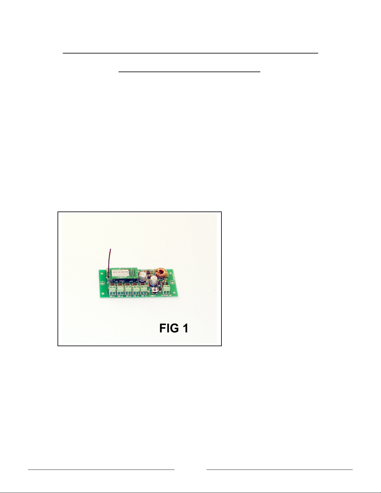
A.Remote Switch Device See Fig 1
Remote Switch Device Connections
BEFORE ANY INSTALLATION; MAKE SURE THERE IS NO POWER TO THE TRACK OR
TO THE REMOTE SWITCH DEVICE. The Remote Switch Device is designed to work on
track power or battery power of at least 6volts DC to a maximum of 24 volts DC. This unit is
self-protected for polarity and input current. Aristo Craft carries a battery box to work with the
Remote Switch Device, CRE 55612 if you do not have track power available.
This Remote Switch Device will handle from one to five switches or accessories each.
Page 1
Page 2
Switches
In the front of the Remote Switch Device there are six terminals five for switch hookups “SW
-1 / SW –5” and one for power input “POWER –IN”. The Remote Switch Device will work with
the fowling switches:
1. Art 11298 Switch Machine Slow Motion New
2. Art 11299 Switch Machine Old
3. LGB switches [TM of Marklin]
4. Most Other G Gauge Switch Machines
Switch Hookups
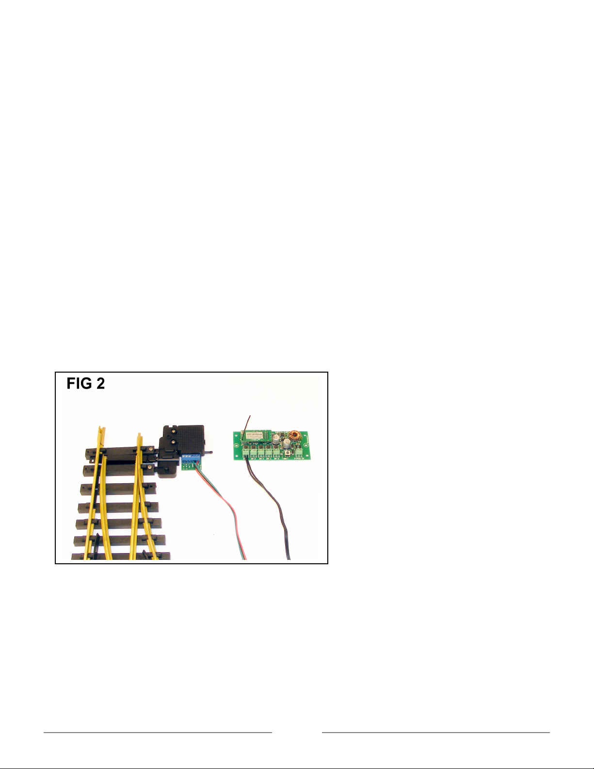
The Art 11298 Switch Machine Slow Motion comes with wires to connect to the switch
machine and to the Remote Switch Device. Do not disconnect the toggle switch from the
wires; this will cause the switch not to work properly even when using with a Remote Device.
The red wire is hooked up to terminal A, the black wire is hooked up to terminal B and the
green wire is hooked up to the common terminal on the slow motion switch machine. Cut the
Plug on the black wires and connect it to the desired terminals marked “SW -1 / SW –5” on
the Remote Switch Device.
Note: The slow motion switch machine works on the SLOW setting only. See Fig 2
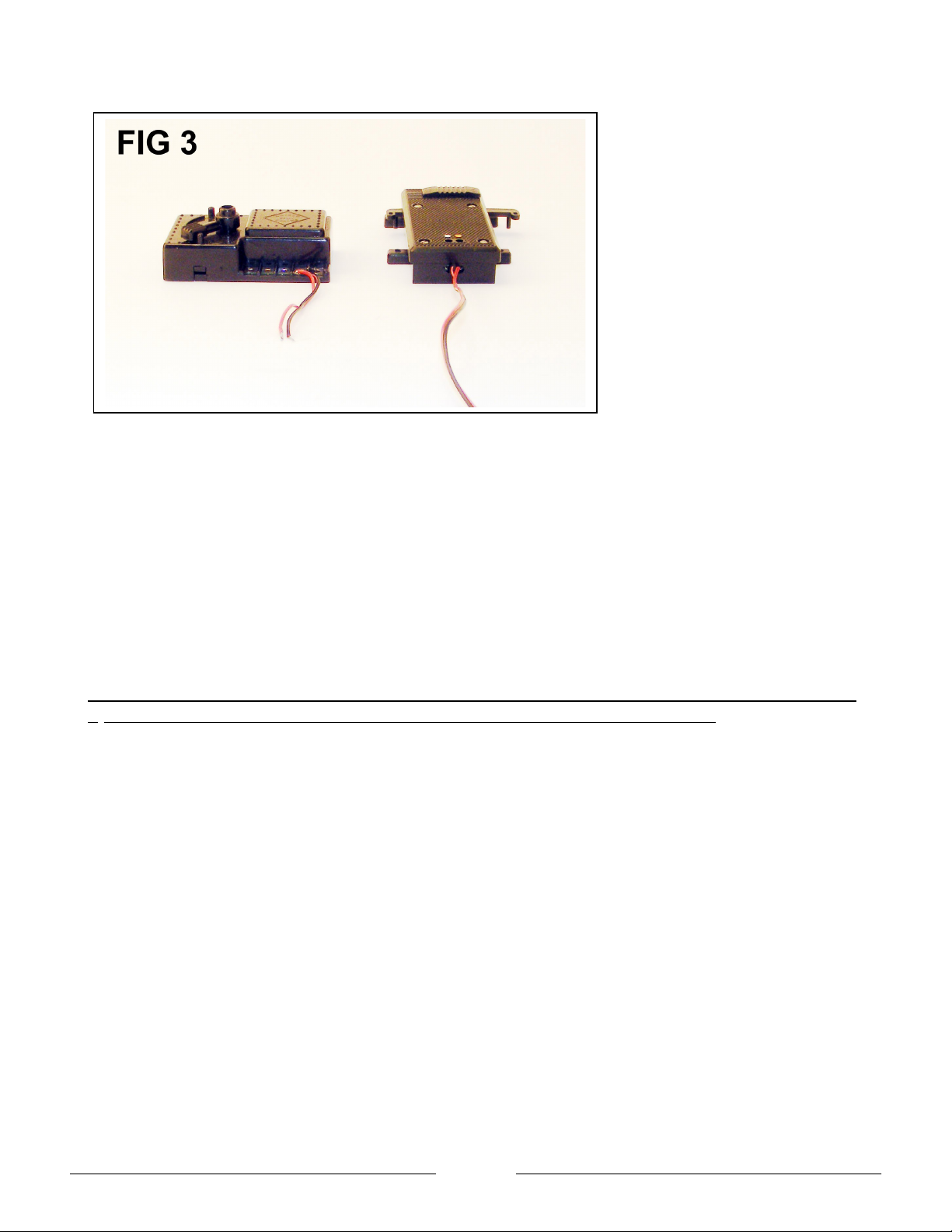
The Art 11299 switch machine and LGB Switches [TM of Marklin] use two wires to hook up on
the switch machine and Remote Switch Device.
Note: These switch machines work on the FAST setting only. See Fig 3
Page 2
Page 3
Power Supply
The Remote Switch Device can be connected directly to a power supply 6 volts to 24 volts or
anywhere from your track layout. This unit can also use battery power 6 volts to 24 volts.
Aristo Craft carries a battery box to work with the Remote Switch Device, CRE 55612 if you
do not have track power available.
In the front of the Remote Switch Device there are six terminals five for switch hookups “SW
-1 / SW –5” and one for power input “POWER –IN”. Take the two wires from the power supply
and connect it to the terminal on the Remote Switch Device marked “POWER –IN” Power
Input.
DO NOT HOOK THE POWER WIRES ON THE FIVE TERMINALS MARKED “SW -1 / SW –
5” SWITCH. THIS WILL BURN THE MAIN BOARD OR CAUSE A SHORT .
Note: This unit is built with polarity protection
Linking the Remote Switch Device to the Transmitter
1. Press the menu button once to select Assign Function on the transmitter.
2. Press the Stop/Enter button to enter Assign Function.
Scroll down to choose the functions below:
a. Bind Address [00] Each Remote Switch Device must have its own bind address
number.
b. Rx TYPE: [ACESS] select ACESS by pressing the left or right arrow. This function must
selected when operating the Remote Switch Device.
c. NAME: [RX –1] Enter a name for the Remote Switch Device. Each device must have a
name before returning to the main LCD screen. Names recommend to enter for the
Remote Switch Device, [RX –1, RX –2, RX –3 etc]
Page 3
Page 4

d. SW-TYPE: [1 –SLOW]: choose “FAST or SLOW” for the switch machines. Some switch
machine need different setting for proper operation. To change the settings on the
switch machines, [SW –1, SW –2, SW –3, SW –4, or SW –5], choose the switch
desired and press the number on the key pad. Press the right or left arrow on the key
pad to change the settings
e. TIMER: [1.0s] choose the time you want the switch to throw from “0.5 second to 5.0
second by pressing the right or left arrow on the key pad.
f. MULTI-SW “OFF”: Change this to “ON” use this function to activate two, three, four or
all five switch machines at the same time.
g. LINKING – Press the link button on the Remote Switch Device for until the red LED light
starts to flash. Let go of the link button and press the “Stop/Enter” button the
transmitter. After a few seconds the red LED will stop flashing and the transmitter will
show PASSED on the LCD screen. You are now linked and ready to operate you
switch machine. See Fig 4
Add the Remote Switch Device to the Main LCD Screen to Enable This Use.
1. Press the Menu button once to go to Main Set Up screen to add your Remote Switch
Device to the Main Screen.
2. Scroll down to Add MU/SU CAB and press the Stop/Enter button
3. CAB NO: CAB –0, Choose a cab number to operate the Remote Switch Device from “-0
to 49”. Each Remote Switch Device must have its own Cab number.
4. Scroll down to “SU [00] RX-1” mode and Select the Bind Address numbers that enter for
the Remote Switch Device. See Fig 5
Page 4
Page 5

Return to the main screen on the Transmitter
a. Press the Menu button twice on the transmitter to return to the main screen. The
Remote Switch Device screen will show up. See Fig 6
Functions Displayed on the Transmitter LCD Screen
The main screen will give you a great detail of information about the switch entered.
First line on the main LCD screen:
Strength of the antenna / signal
SU –Single Unit
RX –1: Remote switch Device name
Switch –which RX-Type enter
Second line on the main LCD screen:
Cab –0 this is the cab number that is entered
Fast –this shows which switch machine is set to Slow or Fast operation
M –SW OFF –this show multi switch function ON or OFF
Page 5
Page 6

Third line on the main LCD screen:
SW –1: shows the first switch and direction
SW –2: shows the second switch and direction
SW –2: shows the third switch and direction
SW –4: shows the fourth switch and direction
SW –5: shows the fifth switch and direction
M –SW: shows the multi switch OFF or ON
Forth line on the main LCD screen:
T 1.0s: shows the Time setting for all of the switch machines.
Link Ok: This indicates that there is a good radio link between the transmitter and the
Remote Switch Device
4.06V –shows the TX battery voltage
Remote Switch Device operation SU
Operate a single switch machine, SW –1:
Press the left or right arrow on the transmitter to activate the switch machine
Operate five switches individually, [SW –1, SW –2, SW –3, SW –4, SW –5,]
Press the left or right arrow on the transmitter to activate the switch machine
Press the top or bottom arrow on the transmitter to choose a switch or press the number
[1 –5] on the transmitter key pad to choose a switch.
To activate two or all five switches at the same time turn the [MULTI-SW] function
“ON” and press the right arrow to add the switch machines.
Select individual Remote Switch Device
To select a Remote Switch Device, press the Press the <<T key to scroll left and the
T>> key to scroll to the right.
SW-BUSY
When the direction button is pressed and the switch machine is in motion a switch busy
signal will show up where ‘link ok’ is. The switch busy signal will go away after all the
switch machine completes time setting. It is recommend to wait until the switch busy
signal completes and then press the other direction necessary.
Switch Machine Direction
Page 6
Page 7

The arrow on the transmitter shows the direction of the switches. You only need to set up the
switches once on the Remote Switch Device. The wires can also reverse on the Remote
Switch Device to change the operating direction of the switch.
Multi Switch Operation
Press the Menu button once to turn on this function choose Assign Function and press the
stop/enter button.
Scroll down to [f. MULTI –SW [OFF] and press the right arrow on the transmitter to turn on the
multi functions. When this function is turn on you will see [1 2---] you are now on multi mode.
To add more switch machines to the multi mode press the right arrow [12345].
To remove the switches from the multi mode function press the left arrow.
Press the menu button twice to return to the main screen.
On the main LCD screen you will see M –SW 12345
SW-BUSY
When the direction button is pressed and the switch machine is in motion a switch busy
signal will show up where ‘link ok’ is. The switch busy signal will go away after the
switch machine completes the time setting. It is recommend to wait until the switch
busy signal completes and then press the other direction necessary.
Note: The multi mode function will operate the switch machines from one through five. It will
not operate the switch machines from five to one as a reverse order.
MUing Remote Switch Device
Before any Remote Switch Device MUed, each Device must have a Bind Address number
and Link to the transmitter. Follow the instructions on Linking the Remote Switch Device to
the Transmitter
MUing More Than One Remote Switch Device
Select a different Cab number to MU the Remote Switch Devices
Example: If you have four Remote Switch Devices under CAB 1, 2, 3, 4, select Cab 5 to
MU the four Remote Switch Devices.
All of the Remote Switch Devices MULTI –SW function must turn ON. To get to
this function press the Menu button once and choose Assign Functions. Press
the Stop/Enter button and scroll down to [f. MULTI –SW]. Press the right arrow
until one through five shows up [12345].
Press Menu button once to return to the Main Set Up screen.
Select 3. ADD MU/SU CAB and press the stop/enter button to enter this function
CAB NO: CAB –0: Chose a different CAB NO by pressing the right arrow
Page 7
Page 8

MU MODE: OFF Press the right arrow to turn the MU mode ON
Scroll down and press the right or left arrow to enter the Remote Switch Device desired
from MU1 –MU6.
Press the Menu button twice to return to the main screen. See Fig 7
Remote Switch Device MU
Operate the MUed Remote Switch Devices
On the main LCD screen the highlighted area [M –SU:] must be on to operate all of the
Remote Switch Device.
Press the right or left arrow and all of the switch machines will activate
When the direction button is pressed and the switch machine is in motion a switch busy
signal will show up where ‘link ok’ is. The switch busy signal will go away after the
entire switch machine reaches time settings. It’s recommend to wait until the switch
busy signal completes and then press the other direction necessary.
Press the up or down arrow to activate the switch machines on desired terminals [SW –
1 through SW –5].
Example: Press the up arrow to “SW –1”, and press the right or left arrow. All of the
Remote Switch Devices that have a switch machine to terminal [SW –1] will activate.
The rest of the switch machines will not activate. See Fig 8
Page 8
 Loading...