

Page 1
CREST ELECTRONICS
www.crest-electronics.net
E-mail-crestelectronics2@yahoo.com
P. #. 201-565-6069
Fax-973-732-1410
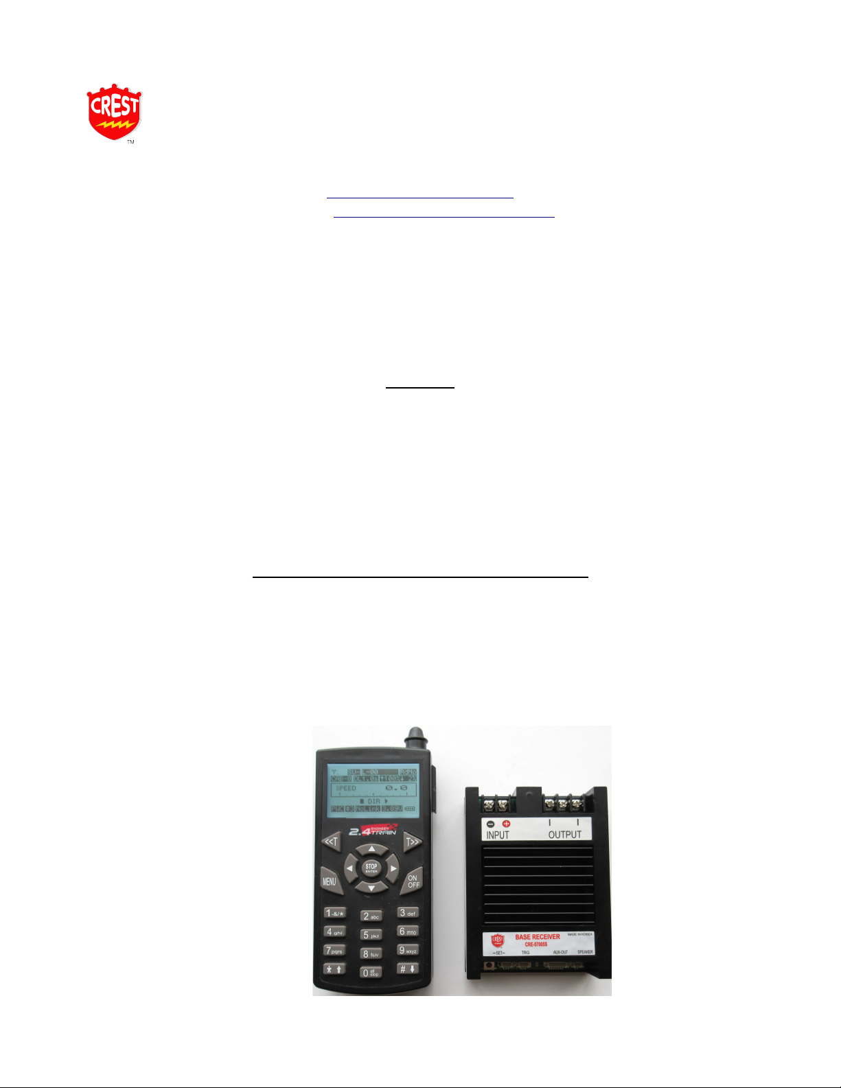
CREST REVOLUTION BASE STATION /SUPER RECEIVER 2.4GHZ
INSTRUCTION MANUAL FOR CRE 57005S
SUPPLEMENTARY MANUAL TO THE MAIN MANUAL FOUND ON YOUR CD OR ON OUR
WEB SITE.
Features
1. Polarity Protection
2. 12 to 26 volts DC
3. 15 AMP
4. Sound Ready
5. Auxiliary Functions.
6. Screw Terminals For Input And Out Put Power
7. Code Signal Light
8. Size: 4.4''X 3''X 1.2''
CRE 57004S Base Station Set Components
a) Transmitter 2.4 GHZ
b) Base Station / Super Receiver 2.4 GHZ
c) Auxiliary Control Harness
d) Remote Link Switch
e) Speaker Plug
f) Chuff Plug
Page 2
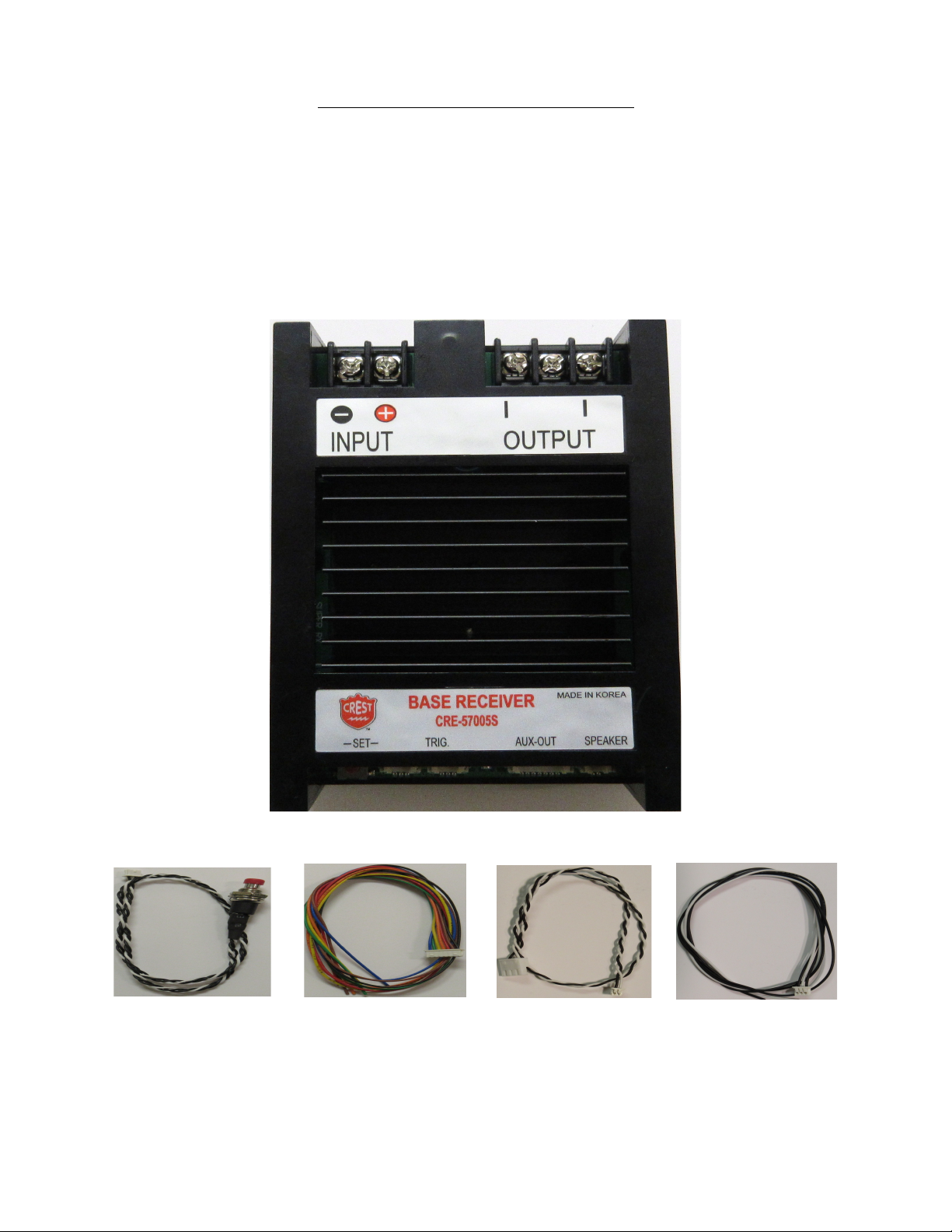
CRE 57005S Receiver Components
a) Base Station / Super Receiver 2.4 GHZ
b) Auxiliary Control Harness
c) Remote Link Switch
d) Speaker Plug
e) Chuff Plug
f) Size: 4.4''X 3''X 1.2'
Base Station Receiver
Not use
HEAT SINK
Link Switch 'SET'
Auxiliary Wire 'AUX'
Speaker Plug
Chuff Plug 'TRG'
Use to program the
transmitter to the
receiver
Use for the smoke
or other
manufacture sound
Connect to a speaker
Use with a reed
switch on steam loco
CRE57070
Page 3

BASE STATION/SUPER RECEIVER CAPABILITIES
This is a base station to control the track or battery power. This receiver will control the one
track your train is running on without modifying the locomotive in any way.
However, the Receiver can also be used in a trailing car to allow multiple trains to run on the
same track.
When used as a Super Receiver you have enough power to control up to 4 locomotives
depending on grades and the number of cars pulled. You will not have the individual control of
several locos, but can operate multiple trains at the same time together. This Super Receiver
will work on either track power or battery power. If track power is used you will need leads
from the truck up to the car to supply the track power to the receiver. Battery is, of course, on
board the trailing car itself. This unit comes with sound, diesel SD or steam SS. The Base
Station/ Super Receiver should be kept inside a structure near the track or in a covered
gondola or box car to protect it from the elements.
Install the Remote Link Switch
Attach the remote link switch connector to the three pin block terminal on the receiver marks
SET.
There is a Red ‘push button’ on the receiver as an alternative Link Switch to program the
receiver, also.
When using a trailing car Locate a place to install the supplied Remote Link Switch where it
will be accessible from the outside of the car.
Transmitter Setup:
For this operation look up pages 11 – 12 on the CD manual on how to set up the Transmitter
and also how to link the Transmitter to the Receiver.
BASIC TRANSMITTER PROGRAMMING PROCEDURE: Download the manual for the “Train
Engineer Quick Start Guide.
You can download and view all the manuals for the Revolution System on or web site
at www.crest-electronics.net under Support.
POWERING YOUR BASE STATION / SUPER RECEIVER
BEFORE ANY INSTALLATION; MAKE SURE THERE IS NO POWER TO THE TRACK OR
TO THE BASE STATION/SUPER RECEIVER.
When the power is hooked up correctly on the receiver the Blue LED power light will flash for
two seconds indicating the power is hook up correctly. The Blue LED light will go away after
two seconds. If the Blue LED light does not flash, reverse the wires on the block terminal on
the receiver input. After the transmitter and receiver is programed, when the receiver receives
signal from the transmitter you will see the Blue LED light comes on solid.
If the Blue LED Flash continuously it can cause by an overload, overheat, also the receiver
power is below 12 volts.
Note Base Station/ Super Receiver will not power up or operate with power below 12 volts.
Page 4

TRACK POWER
The Base Station / Super Receiver is designed to work on track power or battery power of at
least 12 volts DC to a maximum of 26 volts DC. When running from track power with a
controller set your power to the highest setting. Connect DC power wires directly to the Base
Station / Super Receiver on the two screw terminals mark INPUT and connect track wires on
the two outer screw terminals mark OUTPUT. Note do not use the center screw terminal on
the output side.
BATTERY POWER
The Base Station / Super Receiver can also be powered from our Li-Ion Lithium battery. The
maximum voltage must not exceed 26 volts. When operating from batteries, set the
track/battery switch on your locomotive to ‘Battery'. Aristo Craft locomotives have two MU
plugs on both ends of the locomotive; they are used for input power to the locomotive. Crest
guardian battery is recommend to run the Super Base Station.
Cre55610R Battery
Cre55620R Charger.
Note: If needed Crest Electronics has the Male and Female connectors in stock to to wire
your locomotive for battery operation, also the MU connectors to electrically connect more
than one locomotive.
CRE 29511 -Male and Female Connector
CRE 29607-MU Connector
PROGRAMMING THE BASE STATION / SUPER RECEIVER & TRANSMITTER
Look up the CD manual on page 13. Before entering the NAME Under Assign Function you
must choose “Rx Type” [Base Station]. After selecting base station scroll down and enter the
rest of the functions on the transmitter. You can only operate the Lights, smoke board and Aux
Functions when using a training car with the receive installed. On the CD manual you will find
more info.
OPERATING YOUR LOCOMOTIVE
1) Use <<T and T>> keys to select the cab number that you assigned to the locomotive
that you want to operate the locomotive on. The locomotive name & road number will
be displayed on the top line along with SU-, indicating that this is operating as a single
unit locomotive.
2) Use the up and down arrow keys to increase and decrease the locomotives speed.
3) Use the Right Arrow key to go forward and the Left Arrow key to run backwards.
Page 5

Cooling Fan
A cooling fan is recommended for the Base Station/ Super receiver. The cooling fan will help
cool the receiver PC board also with overheat issue. Use a 24 volt fan to cool the receive from
Over Heat. Connect the wires from the fan to the Input power block terminals on the receiver
to power up the fan.
Note the cooling fan for the Base Station sold separately, Item # CRE55499.
Use the double sided stickers to hold the cooling fan on top the receiver.
24 V DC
57005S
CRE55499
CRE55499
COOLING FAN
CRE57005S RECEIVER
Page 6

SOUND CONTROL
On The Transmitter Auxiliary Functions
Press – 1 for ► Turn ON / Turn OFF Sound
Press – 1 for ► Bell
Press – 1 for ► Horn
Press – 1 for ► High Volume
Press – 1 for ► Medium Volume
Press – 1 for ► Low Volume
 Loading...