

Page 1

June 24, 2010
POLK’S MODEL CRAFT HOBBIES, INC. /CREST/ ARISTO-CRAFT/
RMT
698 So. 21st St.
Irvington, NJ 07111
Ph. # 973-351-9800 Fax #973-351-9700 RMT Ph# 908-479-1279
E-mail: aristo@mindspring.com
Service to Hobbyists Since 1935
CREST /ARISTO –CRAFT REVOLUTION BASE STATION /SUPER RECEIVER 2.4
GHZ
INSTRUCTION MANUAL FOR CRE 57005
SUPPLEMENTARY MANUAL TO THE MAIN MANUAL FOUND ON YOUR CD.
Features
1. Polarity Protection
2. 12 to 30 volts DC
3. 15 AMP car type fuse
4. Plug for sound
5. Plug for headlight
6. Screw Terminals For Input And Out Put Power
CRE 57005 System Components
a) Base Station / Super Receiver
b) Auxiliary Control Harness
c) In-put wire plug
d) Remote Link Switch
1
Page 2
June 24, 2010
CRE 57004 System Components
a) Transmitter 2.4 GHZ
b) Base Station / Super Receiver 2.4 GHZ
c) Auxiliary Control Harness
d) Remote Link Switch
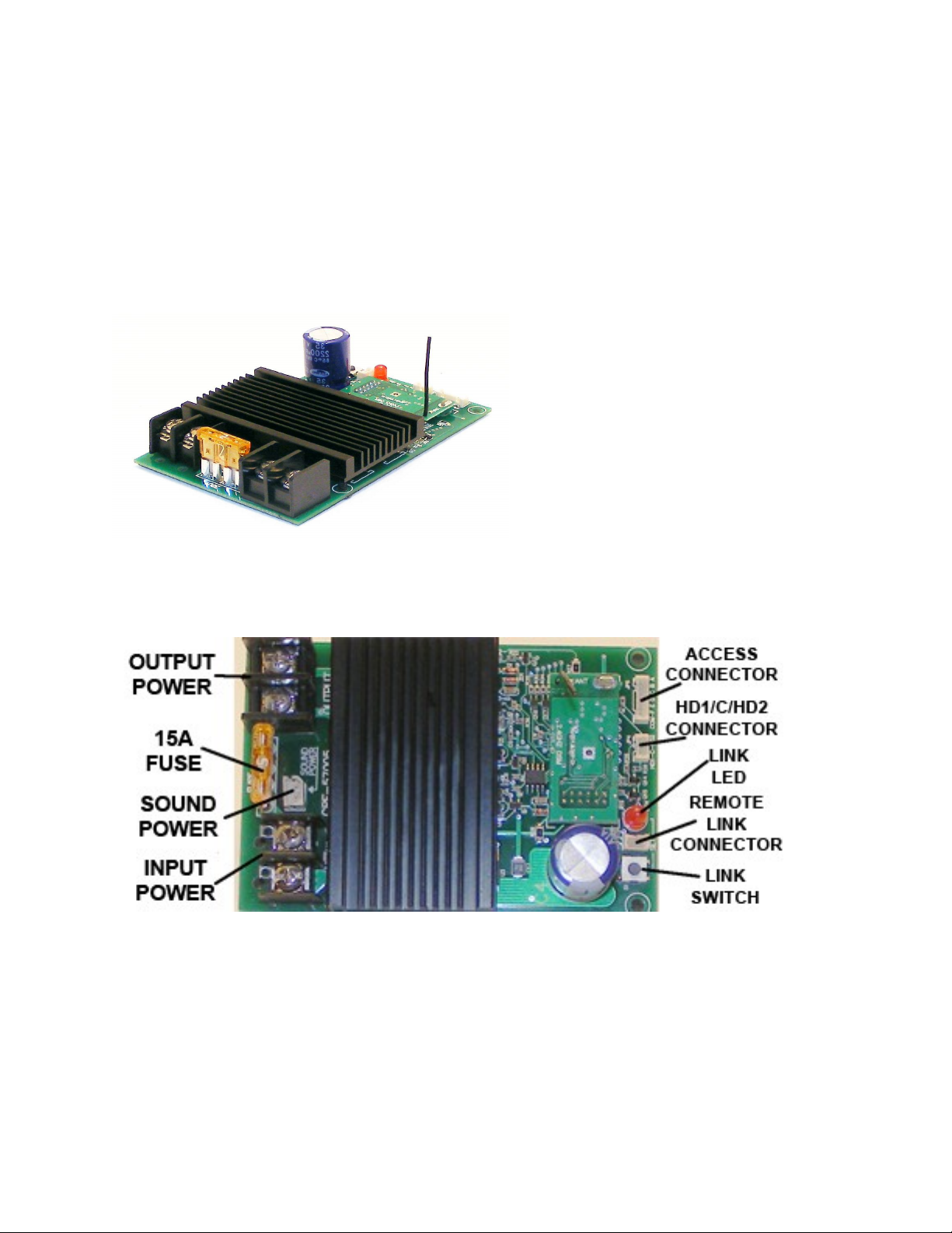
REVOLUTION BASE STATION / SUPER RECEIVER
Photo and Label
BASE STATION/SUPER RECEIVER CAPABILITIES
This is a base station to control the track power in order to radio control the one
track your train is running on without modifying the locomotive in any way.
However, the PCB/Receiver can also be used in a trailing car to allow multiple
trains to run on the same track.
2
Page 3

June 24, 2010
When used as a Super Receiver you have enough power to control up to 5
locomotives depending on grades and the number of cars pulled. You will not
have the individual control of several locos, but can operate multiple trains at the
same time together.
This Super Receiver will work on either track power or battery power. If track
power is used you will need leads from the truck up to the car to supply the track
power to the receiver. Battery is, of course, on board the trailing car itself.
Aristo-Craft is making a trailing car with ball bearing wheels to supply power to
the car on all 8 wheels and will have this ready quite soon. It will hold the Super
Receiver and batteries plus speakers to have easy access to the system and will
be a covered gondola with an easy to remove top.
The Base Station/ Super Receiver should be kept inside a structure near the track
or in a covered gondola or box car to protect it from the elements.
Install the Remote Link Switch
Attach the remote link switch connector to the three pin header on the receiver.
There is a ‘push button’ Link switch on the receiver as an alternative, also.
When using a trailing car Locate a place to install the supplied Remote Link
Switch where it will be accessible from the outside of the car.
Transmitter Setup: for this operation look up page 11 – 12 on the CD manual
BASIC TRANSMITTER PROGRAMMING PROCEDURE: Look up page 11 – 12 on
the CD manual
POWERING YOUR BASE STATION / SUPER RECEIVER
BEFORE ANY INSTALLATION; MAKE SURE THERE IS NO POWER TO THE
TRACK OR TO THE BASE STATION/SUPER RECEIVER.
When the power is hooked up correctly on the receiver the Red Link LED power
light will flash when the remote link switch is pressed. If the Red Link LED does
not flash, reverse the wires on the terminal on the receiver input.
TRACK POWER
3
Page 4

June 24, 2010
The Base Station / Super Receiver is designed to work on track power or battery power
of at least 12 volts DC to a maximum of 30 volts DC. We recommend the CRE 55465 Elite
Dual Power Supply 13 Amp 23 volts or the CRE 55468 Everest Power Supply 15 AMP 24
volts to run on track power or any regulated power supply. When running from track
power using a controller, connect DC power directly to the Base Station / Super
Receiver on the right side terminals and set your power to the highest setting.
Connect wires on the left side terminal on the receiver to the track.
BATTERY POWER
The Base Station / Super Receiver can also be powered from Li-Ion (Lithium Ion),
Ni-MH (Nickel Metal Hydride), Ni-Cd (Nickel Cadmium) or Gel Cell batteries. The
maximum voltage must not exceed 30 volts. Multiple batteries can be wired in
series or parallel to increase voltage or run time. When operating from batteries,
set the track/battery switch on your locomotive to ‘Battery’.
The receiver has two sets of terminals, one is used for power in-put (right hand
side) and the other is used for power output (left hand side). Hook up the battery
power wires to the input terminal of the receiver. Aristo Craft locomotives have
two MU plugs on both ends of the locomotive; they are used for input power to
the locomotive. The recommended pack is CRE556610 and it’s a Lithium Ion state
of the art battery pack.
Note: If needed Aristo Craft has the Male and Female connectors in stock, also
the MU connectors to electrically connect more than one locomotive.
Art 29511 -Male and Female Connector
Art 29607-MU Connector
PROGRAMMING THE BASE STATION / SUPER RECEIVER & TRANSMITTER
Look up on the CD manual on page 13. Before entering the NAME Under Assign
Function you must choose “Rx Type” [Base Station]. After selecting base station
scroll down and enter the rest of the functions on page 14 and 15 on the CD
manual. Do not choose the “Linear” mode”, which has not been included in this
version of the product, while programming the transmitter.
OPERATING YOUR LOCOMOTIVE
1) Use <<T and T>> keys to select the cab number that you assigned to the
locomotive that you want to operate. The locomotive’s name & road number will
be displayed on the top line along with SU-, indicating that this is operating as a
single unit locomotive.
4
Page 5

June 24, 2010
2) Use the up and down arrow keys to increase and decrease the locomotives
speed.
3) Use the Right Arrow key to go forward and the Left Arrow key to run
backwards.
Headlight operation
Look up page 17 – 34 - 35 on the CD manual
Auxiliary Control Harness
Look up page 18 on the CD manual
5
 Loading...