

Page 1
CREST CRE57000
TM
ON BOARD RADIO CONTROL SYSTEM
INSTALLATION
AND OPERATION MANUAL
This manual describes proper installation and
operation of the following products:
CRE57001 REVOLUTION TRAIN ENGINEER 2.4 Ghz TRANSMITTER
CRE57002 REVOLUTION TRAIN ENGINEER 2.4 Ghz RECEIVER
Page 2

INTRODUCTION
Congratulations on your purchase of the Crest Revolution Train Engineer wireless
control system. This product has been manufactured to the highest standards using
only quality components and, with proper care, will provide you with reliable
service. The Revolution TE operates on the 2.4Ghz frequency band for ultimate
stability and interference free operation.
The Revolution TE lets you walk around your model railroad layout and remotely
control your locomotive speed, direction, lights, sounds, and smoke from up to 400
feet away. The Revolution TE was developed to provide the model train enthusiast
with complete integrated control of their dream layout, without the need for
complicated layout wiring or complex control panels.
The Revolution TE receiver is designed to operate between 12 to 24 volts applied
either to the track or from on board batteries. The Receiver is designed for “plug
and play” installation in any Aristo-Craft Locomotive with a DCC/RCC board. The
receiver can also be installed in any large scale locomotive with the use of a supplied
Adaptor Plug. General instructions for custom installations are included in this
manual.
OPERATION OVERVIEW
Before you start working with the Revolution TE there are a few concepts that you
need to understand.
The transmitter and the receivers in your locomotives are designed to communicate
and exchange information about the way you want your trains to operate. In order to
establish a link between them you need to set up some basic parameters that dene
the locomotive for the Transmitter such as the locomotive’s name and road number.
Once these parameters are set, the link between the transmitter and receiver is
nalized by a process called “Linking”. Once linked, the transmitter and receiver are
set to communicate and run your train. As you get comfortable with the Revolution
TE, you can start ne tuning the optional settings for each locomotive. These options
include setting the top speed that you want a locomotive to achieve, the rate at
which you want it to accelerate, how long you want it to delay when the direction is
changed, headlight operation and many more.
The second concept has to do with the Cab Assignment. Once you link a locomotive
receiver to a transmitter you must set the Cab Number that the locomotive will run
under. Cab Numbers range from CAB-0 through CAB49. This allows you to easily
move between as many as 50 Single Unit locomotives and Multiple Unit Consists
while operating your model railroad. CAB-0, CAB-1 and CAB-2 might be used to
operate three different locomotives while CAB-3 can be used to operate those same
three locomotives in a consist. Changing between Single Unit (SU) operation and
Multiple Unit (MU) operation is as simple as selecting a Cab Number.
Once you have an opportunity to experience the process used to operate trains with
the Revolution TE you will nd that Aristo-Craft has found an elegant, easy to
understand solution, to what can be a complex problem.
2
Page 3

CONTENTS
Features . . . . . . . . . . . . . . . . . . . . . . . . . . . . . . . . . . . . . . . 4
System Components . . . . . . . . . . . . . . . . . . . . . . . . . . . . . . . . . 5
Revolution TE Transmitter . . . . . . . . . . . . . . . . . . . . . . . . . . . 6
Revolution TE Receiver. . . . . . . . . . . . . . . . . . . . . . . . . . . . . 7
BASIC OPERATIONS SECTION
Basic Receiver Installation (For Plug-N-Play Locomotives) . . . . . . . . . . . . 7
Link Switch Installation. . . . . . . . . . . . . . . . . . . . . . . . . . . . . 9
Powering your Locomotives. . . . . . . . . . . . . . . . . . . . . . . . . . . . 10
Transmitter Setup . . . . . . . . . . . . . . . . . . . . . . . . . . . . . . . . . 11
Basic Transmitter Programming. . . . . . . . . . . . . . . . . . . . . . . . . . 11
Key Functions. . . . . . . . . . . . . . . . . . . . . . . . . . . . . . . . . 11
LCD Screen - Basic Reference guide . . . . . . . . . . . . . . . . . . . . . 12
Programming a Locomotive . . . . . . . . . . . . . . . . . . . . . . . . . 13
Setting The Cab Number . . . . . . . . . . . . . . . . . . . . . . . . . . . 15
Operating Your Locomotive . . . . . . . . . . . . . . . . . . . . . . . . . . . . 16
Basic Troubleshooting Direction . . . . . . . . . . . . . . . . . . . . . . . 17
Basic Troubleshooting Headlights . . . . . . . . . . . . . . . . . . . . . . 17
ADVANCED OPERATIONS SECTION
Advanced Installations. . . . . . . . . . . . . . . . . . . . . . . . . . . . . . . 18
Auxiliary Control Harness . . . . . . . . . . . . . . . . . . . . . . . . . . 18
CRE57073 Smoke Control Board Installation . . . . . . . . . . . . . . . . 19
Advanced Programming And Functions . . . . . . . . . . . . . . . . . . . 20
Transmitter Operating Screen. . . . . . . . . . . . . . . . . . . . . . . . . 20
Menu Functions and Navigation . . . . . . . . . . . . . . . . . . . . . . . 23
1.ASSIGN FUNCTION . . . . . . . . . . . . . . . . . . . . . . . . . 23
2.USAGE OF CABS . . . . . . . . . . . . . . . . . . . . . . . . . . . 25
3.ADD MU/SU CAB. . . . . . . . . . . . . . . . . . . . . . . . . . . 26
Operating Multiple Locomotives In Consists (MUing). . . . . . . . . . . . 27
4. COPY LOCO . . . . . . . . . . . . . . . . . . . . . . . . . . . . . 28
5. SYSTEM CONFIGURE . . . . . . . . . . . . . . . . . . . . . . . 28
6. RADIO CONFIGURE. . . . . . . . . . . . . . . . . . . . . . . . . 29
7. MY MEMO . . . . . . . . . . . . . . . . . . . . . . . . . . . . . . 29
8. RESET MEMORY . . . . . . . . . . . . . . . . . . . . . . . . . . 30
QUICK MENU LIST . . . . . . . . . . . . . . . . . . . . . . . . . . . . . 30
AUX FUNCTIONS . . . . . . . . . . . . . . . . . . . . . . . . . . . 30
STEP SPEED. . . . . . . . . . . . . . . . . . . . . . . . . . . . . . . 30
A->Z NAME SEARCH . . . . . . . . . . . . . . . . . . . . . . . . . 31
ABOUT SYSTEM . . . . . . . . . . . . . . . . . . . . . . . . . . . . 31
Custom Receiver Installation . . . . . . . . . . . . . . . . . . . . . . . . . . . 31
Adaptor Plug Installation . . . . . . . . . . . . . . . . . . . . . . . . . . . 32
Headlight Connections (Incandescent) . . . . . . . . . . . . . . . . . . . . 34
Headlight Connections (LED lamps) . . . . . . . . . . . . . . . . . . . . . 35
APPENDIX A - Text Entry Help . . . . . . . . . . . . . . . . . . . . . . . . . 36
APPENDIX B - Installation Records . . . . . . . . . . . . . . . . . . . . . . . 37
3
Page 4

REVOLUTION TRAIN ENGINEER FEATURES
SYSTEM FEATURES:
Spread spectrum radio transmission provides immunity from other radio sources•
Range exceeds 400 feet outdoors and 300 feet indoors.•
Continuous bidirectional 2.4Ghz communication between transmitter and •
receiver for smooth operation and operator feedback.
The active locomotive is shown on a graphical, backlit, LCD display The receiver automatically shuts down if overload or overheating occurs -
The error that causes a locomotive shut down is displayed on LCD display Locomotives are identified by name and road number•
Up to 6 locomotives can be linked together (MUed) into a consist•
Up to 10 MU consists can be setup and controlled by one transmitter•
Locomotives can be added or removed from an MU consist without relinking•
TRANSMITTER FEATURES:
Large LCD graphic screen, backlit for night operation•
One handed operation•
Intuitive, simple data input is entered using cell phone style texting techniques•
Memory For Up To 50 Unique Locomotives On Each Transmitter•
Multiple transmitters can operate without interference with one another•
Simultaneous Single Unit ‘SU’ and Multiple Unit ‘MU’ operation•
All Stop Key to provide an emergency stop for all trains on a transmitter•
RECEIVER FEATURES:
Plug and play installation in most Aristo-Craft locomotives•
On-board battery or track power •
Six auxiliary outputs on the receiver to control sound, smoke and lights•
5 Amps continuous power with peak loads up to 8 amps•
Polarity protection•
Overload protection•
INDIVIDUALIZED LOCOMOTIVE PROGRAMMABLE SETTINGS:
Programmable momentum control and forward & reverse delay•
Adjustable start speed •
Adjustable top speed•
Direction control headlights•
Direction control motor setting for MUing locomotives back-to-back.•
Function key assignment for • six auxiliary outputs
Copy locomotive settings for fast replication of similar locomotives•
ADDITIONAL EQUIPMENT AVAILABLE SEPARATELY:
CRE57001 Revolution TE Transmitter•
CRE57002 Revolution TE Receiver•
CRE57073 Smoke Control Board•
CRE57076 Capacitor Board•
CRE57080 TX Battery NI-Cd Battery & Charger•
CRE57072 Transmitter Battery Charger (without batteries)•
4
Page 5
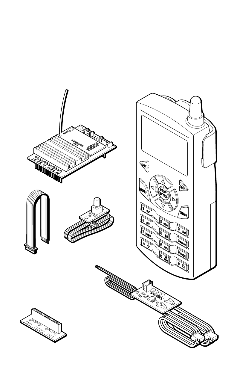
CRE57000 SYSTEM COMPONENTS
REMOTE LINK
SWITCH
CRE57002
RECEIVER
AUXILARY CONTROL
HARNESS
ADAPTER PLUG
(for custom Installations)
CRE57001 TRANSMITTER
CRE57073
SMOKE CONTROL
BOARD
The CRE57000 Crest Revolution TE Wireless Control System consists of the following
components:
CRE57001 Transmitter•
CRE57002 Receiver which includes a Remote Link Switch, an Auxiliary •
Control Harness and an Adaptor Plug
CRE57073 Smoke Control Board.•
5
Page 6
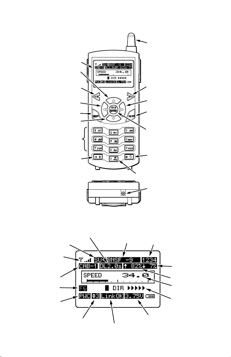
CAB NUMBER
SELECT DOWN
SPEED - FAST
ANTENNA
LCD SCREEN
SPEED - SLOW
NUMBER
LETTER
KEYS
VIEW MU
ENGINES
ALL STOP
CHARGING
JACK
# KEY
DELETE
QUICK MENU
MENU
DIRECTION
(REVERSE)
DIRECTION
(FORWARD)
ON / OFF
STOP / ENTER
CAB NUMBER
SELECT UP
RECEIVER
SIGNAL STRENGTH
ACTIVE CAB
PWC/LINEAR
POWER
SPEED STEP
SU/MU
LOCO
NAME
LOCO ROAD
NUMBER
DELAY SETTING
START SPEED
TOP SPEED
CURRENT SPEED
LOCO DIRECTION
TRANSMITTER
BATTERY VOLTAGE
RECEIVER LINK
AUX FUNCTION
FEEDBACK
REVOLUTION TE TRANSMITTER
LCD SCREEN
6
Page 7
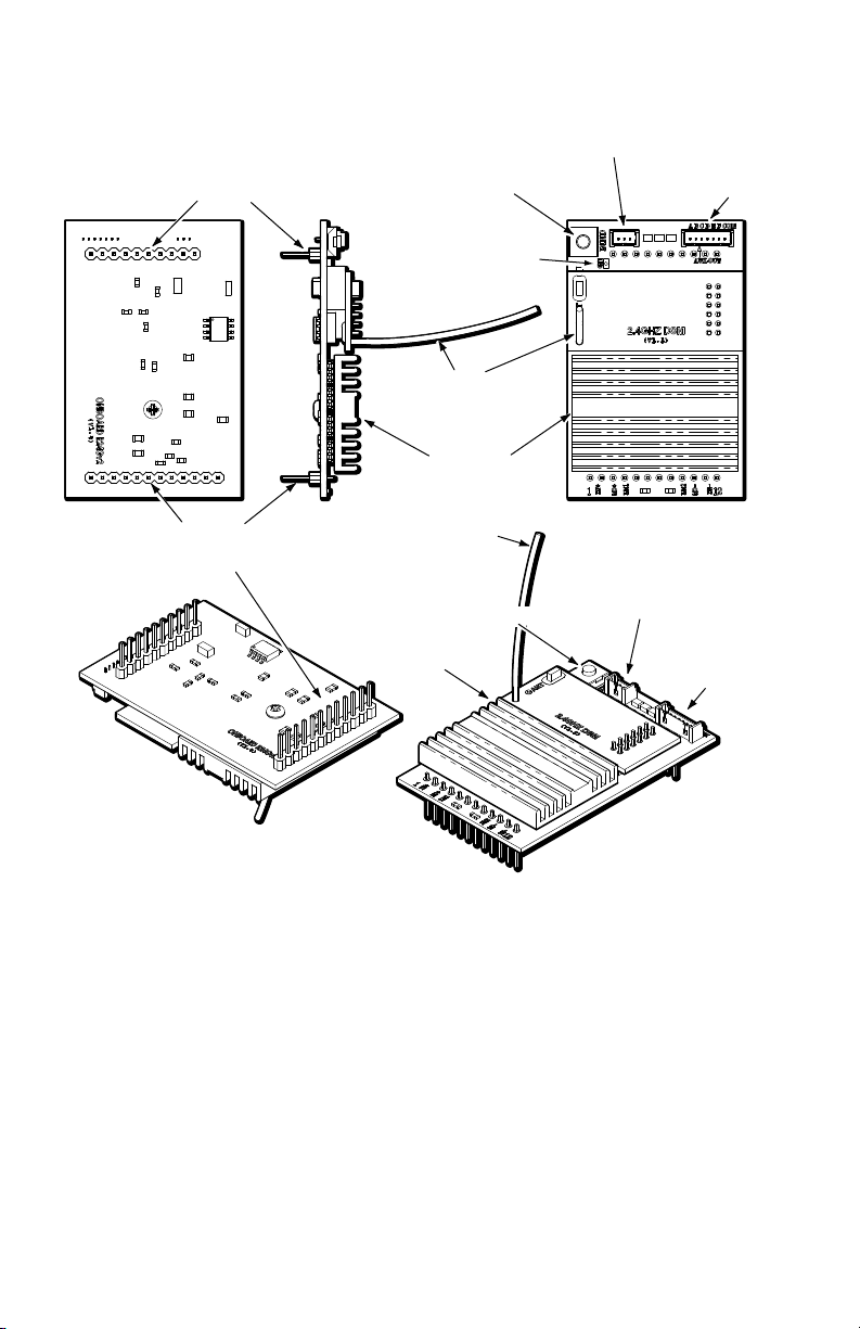
LINK SWITCH
ANTENNA
LINK SWITCH
HEAT SINK
AUXILARY
CONNECTOR
10 PIN SUPPORT
HEADER
12 PIN DCC/RCC
CONTROL HEADER
REMOTE LINK SWITCH
CONNECTOR
REMOTE LINK SWITCH
CONNECTOR
LINK LED
ANTENNA
LINK SWITCH
AUXILARY
CONNECTOR
HEAT SINK
REVOLUTION TE RECEIVER
BASIC RECEIVER INSTALLATION FOR PLUG-AND-PLAY DCC/RCC
EQUIPPED LOCOMOTIVES
You will need the following items for installation:
CRE57002 Revolution TE 2.4 Ghz Receiver•
REMOTE Link Switch •
Phillips head screwdriver•
A drill and drill bits to install the remote Link Switch (if desired)•
NOTE: If the locomotive does not have a DCC/RCC compatible main circuit
board, see the custom installation instructions beginning on page 31 of this
manual.
7
Page 8
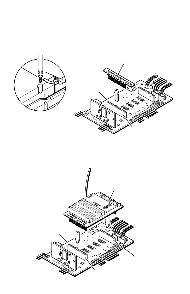
1) Remove the locomotive shell. Refer to the manual included with your locomotive
Engine Main
Circuit Board
Jumper Plug
12 Pin DCC Socket
10 Pin Accessory
Socket
ENGINE MAIN
CIRCUIT BOARD
12 PIN DCC/RCC SOCKET
10 PIN SUPPORT
SOCKET
TE REVOLUTION
RECEIVER
to determine where the DCC/RCC socket is located. Turn the locomotive (or
tender) over, and remove all screws that hold the shell to the frame. Depending
on the model of the locomotive, the number of screws will vary.
2) Remove the jumper plug on the DCC/RCC socket and set it aside. You can
restore the locomotive to its pre-installation state by reinstalling the jumper plug.
3) Install the receiver in the 12 pin DCC/RCC socket and the 10 pin support socket
as shown making sure to match the 12 pin header to the 12 pin socket and the 10
pin header to the 10 pin socket.
8
Page 9
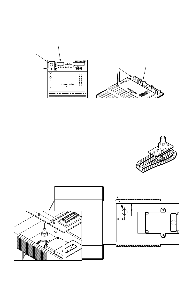
4) Install the Remote Link Switch
1/2"
9/32" DIA.5/16" DIA.
LINK SWITCH
LINK SWITCH
REMOTE LINK SWITCH
CONNECTOR
REMOTE LINK SWITCH
CONNECTOR
LINK LED
LINK SWITCH
REMOTE LINK SWITCH
NOTE: There is a Link Switch on the receiver. If the Link Switch on the receiver
is accessible from outside the locomotive you may wish to skip this step
Locate a place to install the supplied Remote Link Switch where it will be
accessible from the outside of the locomotive, yet obscured from view. Under
a removable hatch or through the bottom of the locomotive or tender are
convenient locations, in most cases. The Remote Link Switch must not be
mounted on a metal or conductive surface since this may cause a short circuit.
A typical installation in the Aristo-Craft SD45 is
shown below.
Drill a 5/16”(8MM) diameter hole in the selected
location. Install the Remote Link Switch through the hole
from inside and secure it with hot melt glue or silicone
adhesive.
5) Attach the remote link switch connector on the Remote Link Switch to the three
pin header on the receiver as shown on the following page.
9
Page 10
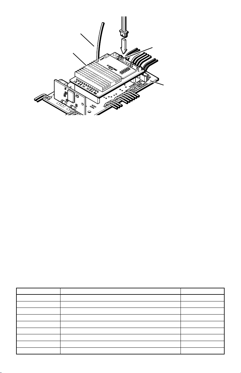
Engine Main
Circuit Board
Receiver
Remote Link
Switch Connector
Link Switch
Header
Antenna
(Fully Extended)
6) Reinstall the locomotive shell. Use care when reassembling the locomotive. Be
careful that you do not pinch any wires between the shell and internal parts of the
locomotive.
THIS COMPLETES BASIC INSTALLATION OF THE RECEIVER. After the
Transmitter set-up is complete, you will have full remote control of your locomotive
speed, direction and lights. If you wish to add advanced options such as remote
operation of smoke and sound please refer to the advanced section later in this
manual.
POWERING YOUR LOCOMOTIVES
TRACK POWER. The Revolution TE receiver will work on voltages ranging from
12 to 24 volts DC. When running from track power, connect DC power directly to
the track and set your controller power to the highest setting, but not more than 24
volts. You can also connect a DC power supply of up to 24 volts, without any speed
controller, directly to the track. Set the track/battery switch on your locomotive to
‘Track’.
BATTERY POWER. The Revolution TE receiver can also be powered from Li-Ion
(Lithium Ion), Ni-MH (Nickel Metal Hydride), Ni-Cd (Nickel Cadmium) or Gel Cell
batteries. The maximum voltage must not exceed 24 volts. Multiple batteries can
be wired in series or parallel to increase voltage or run time. When operating from
batteries, set the track/battery switch on your locomotive to ‘Battery’. The following
batteries and cables are available from Aristo-Craft dealers.
PART NUMBER DESCRIPTION CHARGER
CRE55610 Li-Ion, 2 AMP - 21.5 Volts CRE55620
CRE55650 Ni-MH 2.8 AMP - 12 Volts CRE55660
CRE55653 Ni-MH 2.8 AMP - 19.2 Volts CRE55661
CRE57080 Ni-Cd 1.5 AMP - 12 Volts CRE55660
CRE55493 Gel Cell 3.2 AMP - 3 X 6V CRE55494
CRE55601 Auto Cutoff For Gell Cell Battery
CRE55602 Wire Harness For Battery Set
CRE55611 Y Plug In Parallel
CRE55613 Y Plug in Series
10
Page 11
TRANSMITTER SETUP
ON/OFF
MENU
STOP
ENTER
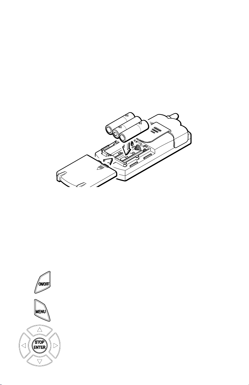
1) REMOVE THE BATTERY COMPARTMENT COVER on the back of the
transmitter case.
2) INSERT THREE “AA” BATTERIES The Revolution Transmitter will operate
on your choice of three “AA” Alkaline, Ni-MH (Nickel Metal Hydride) or Ni-Cd
(Nickel Cadmium) batteries of 1.2 to 1.5 volts each. All three batteries must be
identical, do not mix battery types. Insert the batteries making sure that they face
in the directions indicated in the battery compartment.
Crest Battery Charger CRE57072, is available for charging Ni-Cd batteries
through the charging port in the bottom of the transmitter.
3) REPLACE THE BATTERY COMPARTMENT COVER
BASIC TRANSMITTER PROGRAMMING PROCEDURE
The following section describes the basic programming necessary to begin running
your trains with the Revolution TE system. Since the Revolution TE is an advanced
and full featured system, you may wish to operate your trains at the basic level
described here until you feel ready to take advantage of all of the features that the
Revolution has available. The Revolution TE’s advanced functions are described in
the advanced section of this manual.
Please take the time to familiarize yourself with the transmitter design, key and
button layout as well as the transmitter’s LCD screen on the following pages.
ON/OFF - Press and hold the ON/OFF to turn the Transmitter
on. Press and hold the ON/OFF to turn the Transmitter off.
MENU - Press MENU to select the Transmitter’s setup menus.
While accessing menus, pressing MENU will move you back
one level.
STOP/ENTER - When operating a locomotive the STOP/
ENTER key will STOP the active locomotive and set its
speed to zero. When accessing menu’s, the STOP/ENTER
key will operate as an ENTER key to conrm a selection.
11
Page 12
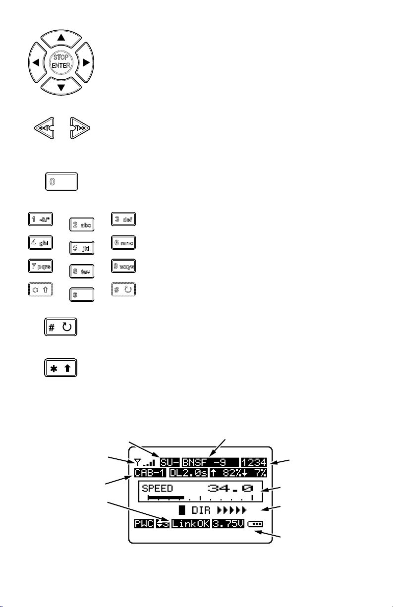
ARROW Keys - When operating a locomotive the up and
<<T
T>>
0
all
stop
3 def
7 pqrs
8 tuv
9 wxyz
0
1 -&/*
4 ghi
5 jkl
6 mno
2 abc
all
stop
RECEIVER
SIGNAL STRENGTH
ACTIVE CAB
SU/MU
LOCO NAME
LOCO ROAD
NUMBER
LOCO DIRECTION
(FORWARD SHOWN)
TRANSMITTER
BATTERY VOLTAGE*
RECEIVER LINK
CURRENT SPEED
*NOTE: THE TRANSMITTER WILL SHUT OFF WHEN THE BATTERY VOLTAGE DROPS TO 3.4 VOLTS.
down arrows (p and q) increase or decrease speed and the left
and right arrows (t and u) select direction. When accessing
menu items the up and down arrows (p and q) scroll between
items and the left and right arrows (t and u) change that item’s
value.
<<T and T>> - Used to select the active locomotive Cab. Press
the <<T key to scroll down and the T>> to scroll up the list. The
locomotive names and road numbers will be displayed on the
main operation screen.
ALL STOP - PRESS AND HOLD the “0 all stop” key and
this immediately stops all locomotives on the same transmitter
and sets their speed to zero. This key is also used to reset a
locomotive after an overload or overheat error occurs.
NUMBER / LETTER KEYS - Use when entering
numeric or textual information the use of these keys
is identical to those on a cell phone. When operating
a locomotive, keys 1 through 6 are used to operate six
auxiliary functions. For example, pressing key “1”
might activate the horn sound. Programming these
keys is covered in the advanced programming section
of this manual.
# (POUND) - When the Operating screen is being
displayed pressing the # key accesses the Quick Menu. During
text entry, this is the ‘space’ key
* (STAR) - When operating an MU consist, pressing this key
selects the locomotive in the consist whose auxiliary functions,
such as smoke or sound, that you want to control.
LCD SCREEN - Basic Reference guide
12
Page 13

PROGRAMMING A LOCOMOTIVE
OPERATION NOTE: Use the p and q keys to highlight a menu option and
then press STOP/ENTER to select the item.
The transmitter and the receivers in your locomotives are designed to communicate
and exchange information about the way you want your trains to operate. In order to
establish a link between them you need to set up some basic parameters that dene
the locomotive for the transmitter and for you, such as the locomotive’s name and
road number. Once these parameters are set, the link between the transmitter and
receiver is nalized by a process called “Linking”. Once linked, the transmitter and
receiver are set to communicate. Finally you must assign a Cab Number to your
locomotive and then you are ready run your train with the Revolution TE.
As you get comfortable with the Revolution TE, you can start ne tuning the optional
settings for each locomotive, as described, in the advanced section of this manual.
1) Turn on the transmitter by pressing On/
Off. The main “Operating” screen will be
displayed.
2) Press MENU to access the MAIN SET
UP menu.
MAIN SET UP
1.ASSIGN FUNCTION ¤
3) Press the STOP/ENTER key (or the ‘1’
key) to select:
1.ASSIGN FUNCTION
2.USAGE OF CAB
3.ADD MU/SU
4.COPY LOCO
5.SYSTEM CONFIGURE
4) a.LINK ADDR - The link address for the locomotive must be chosen.
This number is different for each locomotive and is a number from “00” to “49”.
The default entry, when you access the Assign Functions menu, is ‘49’. Use
link address [00] for the rst locomotive.
Note that you can quickly move to link
address [00] by pressing the STOP/
ENTER key. To select another address,
use the t and u keys until the address
you want is displayed. This is also the
method used to access previously dened
locomotives for editing.
13
1.ASSIGN FUNCTIONS
a.LINK ADDR [49] ¤
b.RxType [OnBoard]
c.NAME [L49 ]
d.ROAD No. [RdNo]
e.MOMENTUM [ 10%]
Page 14

5) c.NAME - Use the p and q keys
move to NAME. Use the keypad to
type letters or numbers to name the
locomotive. Names may be up to 9
characters long. There is a guide to
entering names in Appendix “A” on
page 35 of this manual.
1.ASSIGN FUNCTION
a.LINK ADDR [00]
b.RxType [OnBoard]
c.NAME [GN SD45 ] ¤
d.ROAD No. [RdNo]
e.MOMENTUM [ 10%]
6) d.ROAD NO. - Use the p and
q keys move to ROAD No. Enter a
1.ASSIGN FUNCTION
road number of up to four characters
using the number keypad.
7) Place the locomotive on the track.
a.LINK ADDR [00]
b.RxType [OnBoard]
c.NAME [GN SD45 ]
d.ROAD No. [400 ] ¤
e.MOMENTUM [ 10%]
8) Apply power. If running on batteries
make sure the locomotive’s battery is
12 to 24 volts and is fully charged. If using track power, apply 12 to 24 volts to
the track.
9) m.LINKING - Use the p and
q keys move to LINKING. Press
and hold the Link Switch on the
locomotive. Release the Link Switch
when the locomotive’s lights begin
ashing.
NOTE: There is an LED on the
1.ASSIGN FUNCTION
i.HD LIGHT [ ON]
j.TOP SPEED [100%]
k.START SPEED[ 0%]
l.AUX FUNC. SETUP
m.LINKING £
Revolution TE Receiver that also
ashes during this linking process. See
the illustration of the receiver, on page
7, to locate the LED.
While the lights (and LED) are ashing
press the STOP/ENTER key on the
transmitter.
In a moment the screen will show that
1.ASSIGN FUNCTION
i.HD LIGHT [ ON]
j.TOP SPEED [100%]
k.START SPEED[ 0%]
l.AUX FUNC. SETUP
m.LINKING PASSED! £
the programming of the unit has been
successful and the ashing will stop.
11) Press the MENU key once to return to the Main Menu.
BASIC LOCOMOTIVE PROGRAMMING IS NOW COMPLETE.
14
Page 15

Setting the CAB number
Each locomotive must be assigned to a cab number. This provides a simple way
to choose locomotives from the main
operating screen.
MAIN SET UP
1) Press MENU to display the main set up
menu.
3) Press the 3 key to select:
3.ADD MU/SU
4) Use the p and q keys to select a CAB
number. CAB-0 is the rst available
active locomotive in the list so you
want to start here.
5) Use the p and q keys to select
SU [49] L49
1.ASSIGN FUNCTION ¤
2.USAGE OF CAB
3.ADD MU/SU
4.COPY LOCO
5.SYSTEM CONFIGURE
MAIN SET UP
1.ASSIGN FUNCTION
2.USAGE OF CAB
3.ADD MU/SU ¤
4.COPY LOCO
5.SYSTEM CONFIGURE
3.ADD MU/SU CAB
CAB NO: CAB-0 ¤
MU MODE: OFF
SU [49] L49
6) Use the t and u keys to scroll thru
the locomotive listings until you nd
the locomotive (by Link Address) that
you programmed previously. As shown
in the example to the right for a GN
3.ADD MU/SU CAB
CAB NO: CAB-0
MU MODE: OFF
SU [00] GN SD45 ¤
SD45.
7) Press the MENU key to return to the
Main Menu
The transmitter and receiver are now linked an ready to operate your
locomotive. When you feel ready to move into advanced features and programming
please turn to the advanced setup section in this manual.
15
Page 16

OPERATING YOUR LOCOMOTIVE
1) Use <<T and T>> keys to select the cab number that you assigned to the
locomotive that you want to operate. The locomotive’s name & road number will
be displayed on the top line along with SU-, indicating that this is operating as a
single unit locomotive.
2) Use the up and down arrow keys (p and q) to increase and decrease the
locomotive’s speed.
3) Use the Right Arrow key ( u) to go forward and the Left Arrow key (t) to run
backwards.
While it is preferred that you stop you trains gradually by using the down arrow
(q) key you can stop the selected locomotive quickly by pressing STOP/ENTER.
You can now add additional locomotives following these same procedures but
using a different Link Address for each new locomotive.
Controlling two locomotives (trains) independently, at the same time
1) Make sure that both locomotives have been identied in the transmitter, that
linking has been successful and that the locomotives have each been assigned a
Cab Number.
2) Place each locomotive on the track, separated by some distance .
3) Use the <<T and T>> keys until the display shows cab number, name and road
number for the locomotive that is in front.
4) Use the UP Arrow (p) key to start it running slowly in a forward direction.
5) Select the other locomotive with the <<T and T>> keys. Use the p and q keys
to get it running.
Note that the displayed speed for both locomotives may not be the same when they
are actually running at the same speed as it can vary from locomotive to locomotive.
You can continue to operate each locomotive independently by switching from one
CAB to the other using the <<T and T>> keys and then make changes in speed or
operate accessories.
That is all there is to get up and running. With practice you will become a master
at controlling your trains. When you are ready to take the next step please read the
advanced section of this manual to learn how to make the most of the Revolution TE.
16
Page 17

BASIC OPERATING TROUBLESHOOTING
“The engine runs backwards when the transmitter is set to forward”
1) Press MENU to display the MAIN SET
UP menu.
2) Press the STOP/ENTER key to select:
1.ASSIGN FUNCTION
3) Use the p and q keys to scroll down
the list of functions to:
g.MOTOR
4) Use the t and u keys to toggle motor direction between NORmal and
REVerse.
5) Press MENU to exit to the main menu screen.
6) Press MENU again to exit to the operating screen.
The locomotive will now respond to direction in the opposite way that it did initially
and should now match the transmitter indication.
1.ASSIGN FUNCTIONS
c.NAME [L49 ]
d.ROAD No. [RdNo]
e.MOMENTUM [ 10%]
f.DELAY [3.0s]
g.MOTOR [NOR] ¤
“My engine’s headlight does not match the direction of the locomotive”
1) Press MENU to display the main set up
menu.
2) Press the STOP/ENTER key to select:
1.ASSIGN FUNCTION
3) Use the p and q keys to scroll down
the list of functions to:
h.HD DIR
4) Use the t and u keys to toggle the headlight direction between NORmal and
REVerse.
5) Press MENU to exit to the main menu screen.
6) Press MENU again to exit to the operating screen.
The headlight will now match the direction of travel of your locomotive.
17
1.ASSIGN FUNCTIONS
d.ROAD No. [RdNo]
e.MOMENTUM [ 10%]
f.DELAY [3.0s]
g.MOTOR [REV]
h.HD DIR [NOR] ¤
Page 18

ADVANCED OPERATIONS, INSTALLATIONS AND PROGRAMMING
Engine Main
Circuit Board
Receiver
Auxiliary Control
Harness
Remote Link
Switch Harness
Black Wire
1 - Blue
2 - Green
3 - Yellow
4 - Orange
5 - Red
6 - Brown
7 - Black
Wire Color I.D.
AUXILIARY CONTROL HARNESS
An Auxiliary Control Harness is supplied with the
Revolution TE Receiver. The Auxiliary Control
Harness plugs into a seven pin auxiliary wiring
connector at one end of the receiver circuit board.
The wires, which correspond to keys 1 thru 6 on the
transmitter, are connected to control functions of your
choice.
NOTE: The functions listed in the table below
represent how we envisioned the system to operate.
This does not mean to say that this is the only way that
you can use each of the six functions. More important is
that you assign a purpose to each auxiliary function and
stay consistent from one locomotive to the next so that
you know which key does what on each of your locomotives.
The six switch positions will need to be connected to the accessory you wish to
control with the Transmitter. Please refer to the manufacturer’s instructions for
connecting sound triggers when using third party sound systems.
The six functions of the Auxiliary Control Harness are independently programmable
and intended to operate as follows:
AUXILIARY CONTROL HARNESS
Wire #/Color Tx Key Typical Use Setting
1 Blue 1 Horn/Whistle sound Momentary
2 Green 2 Bell sound Latching
3 Yellow 3 Brake sound Momentary
Orange 4 Other sound Momentary
4
5 Red 5 Running/Cab/Ditch Lights Latching
Brown 6 Smoke
6
(use with CRE57073 Smoke Control Board) Latching
7 Black N/A Common (ground) for all functions
18
Page 19

CRE57073 SMOKE CONTROL BOARD
Plugs go to
Smoke Unit(s)
Connect to Auxiliary
Control Harness
Plug in Power
for Smoke Unit(s)
Solder
Heat Shrink Tubing
Auxiliary Harness
Brown Wire
Black Wire
In order to control a smoke generator which has a relatively high power draw, a
Smoke Control Board (Available separately CRE57073) has been designed to work
with the Revolution TE Receiver. This Smoke Control Board has been designed to
be used with the Auxiliary Control Harness to remotely operate smoke generators by
acting as an electronic switch or relay. The Smoke Control Board has the ability to
operate two smoke generators simultaneously.
1) If you use heat shrink tubing to insulate solder joints, place a short piece on the
black wire and another on the brown wire of the Auxiliary Control Harness.
Solder the black wire from the Smoke Control Board to the black wire in the
Auxiliary Control Harness. Solder the white wire from the Smoke Control Board
to the brown wire on the Auxiliary Control Harness. Carefully heat the heat
shrink tubing (or use electrical tape) to insulate the solder joints.
2) Unplug the wire harness that is plugged into the smoke generator in your
locomotive and plug this connector into the socket on the Smoke Control Board.
If your locomotive has dual smoke generators, like the Aristo-Craft E8, unplug
both smoke units and plug only one of these connectors into the Smoke Control
Board.
3) Plug one of the connectors from the Smoke Control Board (either one will work)
into the smoke generator, where the original connector was plugged in. If you
have a second smoke generator in your locomotive, plug the other connector from
the Smoke Control Board into the second smoke unit.
4) Use double sided foam tape to securely mount the Smoke Control Board to the
interior of the locomotive using care that the circuit board does not come in
contact with any metal inside of the locomotive.
5) Set the smoke switch (in the locomotive) to on. This switch should remain on.
6) Refer to the Advanced Programming section of this manual to program F6 to
‘LATCH’ under AUX FUNC. SETUP in the locomotive ASSIGN FUNCTIONS
menu.
The onboard Revolution receiver now has control of the locomotive smoke
generator. When you want to operate the smoke generator in your locomotive, add
smoke uid to the smoke generator and when operating the locomotive, simply press
key ‘6’ to turn the smoke on and press key ‘6’ again to turn the smoke off.
19
Page 20

ADVANCED PROGRAMMING AND FUNCTION INFORMATION
RECEIVER
SIGNAL STRENGTH
ACTIVE CAB
PWC/LINEAR
POWER
SPEED STEP
SU/MU
LOCO
NAME
LOCO ROAD
NUMBER
DELAY SETTING
START SPEED
TOP SPEED
CURRENT SPEED
LOCO DIRECTION
TRANSMITTER
BATTERY VOLTAGE
RECEIVER LINK
AUX FUNCTION
FEEDBACK
The following section is a comprehensive list of functions, displays and descriptions
of the options available under each menu item. Accessing and setting these functions
uses exactly the same techniques described in the basic programming section of this
manual.
The Transmitter Operating screen
OPERATING SCREEN - First Line
Receiver Signal Strength - The antenna symbol and signal bars, in the upper left
corner of the screen shows the strength of the radio signal between the transmitter
and the locomotive’s receiver. This is reference information only and has no user
setable function.
SU/MU - SU- indicates that the locomotive under control is a single independent
unit. MU2 or MU3 indicates that a Multiple Unit conguration of 2 or more
locomotives is being operated. This is also reference information and it indicates
the selected CAB type.
Loco Name - The active locomotive’s name is programmed by the operator when
programming locomotives
Loco Road Number - The active locomotive’s road number is programmed by the
operator when programming locomotives
OPERATING SCREEN - Second Line
Cab # - The cab number is associated with the locomotive that is being controlled.
This number is programmed by the operator under item 3 of the main menu
ADD MU/SU CAB which is used to assign either single locomotive or multiple
locomotives to a CAB Number for operating purposes. This is what makes MUed
locomotives work as a unit.
20
Page 21

Delay Setting - Is the number of seconds that the train will stay stopped when its
direction is changed. DL2.0s in this example means that the locomotive will
pause for 2.0 seconds before it reverses direction. This setting is available for
programing by the operator when a locomotive is being dened under Item 1,
ASSIGN FUNCTIONS
Top Speed - The locomotive’s maximum speed is expressed as a percentage of the
maximum possible speed. This setting is available for programing by the operator
when a locomotive is being dened under Item 1, ASSIGN FUNCTIONS. TOP
SPEED is useful when the operator would like to limit the maximum speed of a
locomotive to a scale speed for realistic operation. This item can also be useful if
you wish to limit the speed at which children an operate a locomotive.
Start Speed - The locomotive’s start speed is expressed as a percentage of the
amount of power required for the locomotive to begin to move. This setting is
available for programing by the operator when a locomotive is being dened
under Item 1, ASSIGN FUNCTIONS. START SPEED is used to reduce the
dead zone between speed setting 0 and the speed setting at which the locomotive
begins to move.
OPERATING SCREEN - Current Speed Box
Current Speed - shows the locomotive’s current speed as a percentage of the
maximum possible speed. At the bottom of this box the speed of the locomotive
is shown graphically in the form of a bar.
OPERATING SCREEN - Loco Direction Line
Loco Direction - shows the direction of travel for the active locomotive. Arrows
pointing to the right indicate forward while arrows pointing to the left indicate
reverse
Aux Function Feedback - Flashes when an Auxiliary Function key is pressed.
OPERATING SCREEN - Bottom Line
PWC/Linear Power - The rst item on the bottom line shows that the system is
using PWC (Pulse Width Coding) speed control.
Speed Step - This shows the sensitivity level for speed of reaction after pressing
the t and u keys. This is an operator dened setting under the QUICK MENU
LIST. For switching you might want a lower sensitivity and for big trains a faster
key reaction. This setting is applied to all locomotives being controlled by the
transmitter.
LinkOK or NOLink - tells whether the transmitter and receiver of the active
locomotive are communicating. This same area on the display will show error
messages such as OVERLOAD or OVERHEAT. This is reference information
only and has no user setable function.
Normally the transmitter’s main control display shows LinkOK on the bottom
line of the screen. This indicates that there is a good radio link between the
transmitter and the receiver in the locomotive. If that link is lost due to an
21
Page 22

exhausted battery, excessive distance, a short circuit or open circuit on the track, a
derailment or no power on the track the message will change to NOLink.
When the amperage drawn by a locomotive exceeds 8 amps, the capacity of the
onboard receiver, which can continuously supply 5 amps, the receiver will shut
down and the transmitter will display OVERLOAD on the LCD.
The receiver will send an OVERHEAT signal to the transmitter if the receiver’s
temperature exceeds 175 degrees Fahrenheit. If the receiver overheats wait for 5
to minutes for the receiver to cool before continuing to operate it.
After you correct an overload or overheat condition press the zero key [0] on the
transmitter keypad to reset the error message.
Transmitter Battery Voltage - Shows the voltage level of the transmitter’s batteries.
Fresh alkaline batteries should show about 4.5 volts for example. The last item is
a graphic of the transmitter’s battery level. These are for operator reference only
and have no user setable function.
NOTE: The Transmitter will shut off when the battery voltage drops to 3.4 Volts
NOTES:_____________________________________________________________
____________________________________________________________________
____________________________________________________________________
____________________________________________________________________
____________________________________________________________________
____________________________________________________________________
____________________________________________________________________
____________________________________________________________________
____________________________________________________________________
____________________________________________________________________
____________________________________________________________________
____________________________________________________________________
____________________________________________________________________
____________________________________________________________________
____________________________________________________________________
____________________________________________________________________
____________________________________________________________________
____________________________________________________________________
____________________________________________________________________
22
Page 23

MENU FUNCTIONS AND NAVIGATION
In this section each menu item is shown along with comments about its use.
The MAIN SET UP menu is accessed by pressing MENU from the main control
screen. To navigate this menu use the p and q keys to select the item that you wish
to edit and press ENTER to access the item submenu.
1.ASSIGN FUNCTION - This Menu
is used to dene individual locomotives.
To navigate this menu use the p and q
keys to select the function that you wish
to change. To change a setting that has a
pre-dened range, use the t and u keys.
Under NAME and ROAD NO. Use the
number and letter keys to add text and
MAIN SET UP
1.ASSIGN FUNCTION¤
2.USAGE OF CAB
3.ADD MU/SU
4.COPY LOCO
5.SYSTEM CONFIGURE
numbers. When programming is complete,
press Menu to return to the Main Menu.
After a new locomotive is dened in this Menu, you must then assign the new
locomotive a Cab Number in Menu 3.ADD MU/SU CAB, before you can control
your newly dened locomotive.
FUNCTION SETTINGS
a.LINK ADDR - The link address for the
locomotive must be chosen. This number
is different for each locomotive and is a
number from “00” to “49”. Use the t and
u keys to select a Link Address. 00 is the
rst available address in the list and should
be used for the rst locomotive. Note that
you can quickly move to address 00 by
pressing the STOP/ENTER key.
b.RxType - This menu item tells the
transmitter which type of receiver is being
dened. OnBoard is the receiver type used
in locomotives while BASE RX is the
1.ASSIGN FUNCTIONS
a.LINK ADDR [49]
b.RxType [OnBoard]
c.NAME [L49 ]
d.ROAD No. [RdNo]
e.MOMENTUM [ 10%]
f.DELAY [0.0s]
g.MOTOR [NOR]
h.HD DIR [NOR]
i.HD LIGHT [ ON]
j.TOP SPEED [100%]
k.START SPEED[ 0%]
l.AUX FUNC. SETUP
m.LINKING
receiver type used for stationary functions
such as remote switch control. Use the t
and u keys to select the Receiver Type that you are dening. Once linked, the
receiver type cannot be changed without relinking.
c.NAME - This is where you give your locomotive an easy to identify name.
Use the keypad to type letters or numbers to “Name” the locomotive. Names may
be up to 9 characters long. Something like BNSF GP40 or UP -9 or some similar
description is good. There is a guide to entering text in Appendix “A” (page35).
d.ROAD NO. - Enter the road number of the locomotive being dened. One to
four characters is allowed. This lets you distinguish between two locomotives that
were both named BNSF GP40 for example.
23
Page 24

e.MOMENTUM - If momentum is set to 0 (zero) your locomotive will accelerate
rapidly if you press and hold the UP ARROW key. Its speed will instantly
become what it is set to. As the momentum setting is increased the time that it
takes the locomotive to catch up with the speed setting you set increases. This
means that you can set the speed to 60% by holding the UP ARROW key for a
few seconds but the locomotive may take several more seconds to actually make
it to that speed. Use the t and u keys to select the amount of Momentum that
you want to apply to the locomotive you are dening.
Momentum And Step Speed (described later) both effect how quickly a
locomotive will reach its top speed.
f.DELAY - When the direction of the locomotive is reversed this setting
determines how long, in seconds, that the locomotive will be completely stopped
before it starts up again in the other direction. The range is 0 to 5 seconds in
1/10th second increments. Use the t and u keys to select the amount of delay, in
seconds, that you want your locomotive to wait before reversing direction.
g.MOTOR - This item sets the default direction of travel when the transmitter
says the locomotive is going forward. This can be set to NOR (normal) or REV
(reverse). If set to NOR the locomotive will go forward when the transmitter
shows that it is going forward. If set to REV the locomotive will go backwards
when the transmitter shows that it is going forward. This is used primarily when
you are operating multiple locomotives (MUing) and you want them to run backto-back. Use the t and u keys to select the Motor default direction.
h.HD DIR - This can be set to NOR (normal) or REV (reverse). If set to NOR
the headlight on the locomotive will come on when the locomotive is going
forward. If set to REV the headlight will come on when the locomotive is going
backwards. This is useful if your headlights do not match the direction of travel
of the locomotive. Use the t and u keys to change the headlight direction.
i.HD LIGHT - This can be set to ON or OFF. If set to ON the headlight will
operate normally. If set to OFF the headlight will not function. This function is
used when adding locomotives into a Multiple Unit consist. Typically only the
lead locomotive has it’s headlight on when operating and all trailing units have
their headlights off. Use the t and u keys to set the headlight to On of Off.
j.TOP SPEED - Sets the locomotives top speed as a percentage of its possible
top speed. This comes in handy if you have visitors who are operating your trains
and have been known to run them at too high a speed. If you set this to 70% that
is all the faster the locomotive will go, 70% of its possible top speed. Use the t
and u keys to set the locomotives Top Speed.
k.START SPEED - Sets the speed at which acceleration of the locomotive
begins. If you have a large locomotive or one that is pulling a long, heavy train
you can set the start speed so that the power level will jump to the set percentage
as soon as you begin accelerating. For example, if you have a locomotive that
doesn’t start moving till the throttle setting is at 25% you can set the start speed to
that number and not have to wait for the speed to get to that level before the train
moves. As soon as you press the UP ARROW key the speed will jump to 25%
24
Page 25

and increase from there as the UP ARROW key is held. Use the t and u keys to
set the Start Speed of the locomotive.
l.AUX FUNC. SETUP - This menu item is used to set each of the function
keys to operate either as momentary or
latching. MOMENTARY means that the
function being controlled is on while the
Function key is pressed and turns off when
the key is released. LATCHING means
that the function being controlled is turned
on when the Function key is pressed and
remains on till the same Function key is
pressed again.
AUX FUNC. SETUP
AUX MODE: BASIC
F1: MOMENTARY
F2: MOMENTARY
F3: MOMENTARY
F4: MOMENTARY
F5: MOMENTARY
F6: MOMENTARY
AUX MODE: BASIC vs. EXTEND
- Select either BASIC or EXTEND. In
BASIC mode, you will be able to control function keys F1 thru F6. If your
receiver supports more than six auxiliary functions then EXTEND mode is
chosen so that you can control up to 16 auxiliary functions, F1 thru F16.
Use the t and u keys to set each Aux Function to either momentary or latching.
m.LINKING - This nal menu item is used to establish a Link between the
transmitter and the receiver that you just dened.
1) Press and hold the Link Switch on the receiver or locomotive until the LED
on the receiver, or lights on the locomotive, begin to ash.
2) While the LED/lights are ashing press the ENTER key on the transmitter.
In a moment the screen will show that the programming of the unit has been
successful and the ashing will stop. Once linked, the function settings are saved for
this locomotive. Press MENU to return to the Main Menu.
2.USAGE OF CABS
The Revolution transmitter can store up to as
many as 50 locomotives. Since it is unlikely
that each of us would have this number of
locomotives active at one time you can use this
menu item to limit the number of locomotives
that show up when you press the <<T and T>>
keys while viewing the control screen.
1) From the Main Menu screen use p and q
to select 2.USAGE OF CABS and press
ENTER
2) Use the t and u keys to increase or
decrease this range from CAB-0 thru
CAB49.
Press MENU to save this set-up and return to
the Main Menu.
25
MAIN SET UP
1.ASSIGN FUNCTION
2.USAGE OF CAB
3.ADD MU/SU
4.COPY LOCO
5.SYSTEM CONFIGURE
2.USAGE OF CABS
CONTROL CAB
CAB-0 TO CAB-5
¤
Page 26

3.ADD MU/SU CAB
This Menu is used each time a new locomotive
is added to the transmitter. Its purpose is to
assign a Cab Number a locomotive so that it
can be quickly identied and selected from the
main operation screen. This is where you assign
a locomotive it’s Single Unit (SU) Cab Number
MAIN SET UP
1.ASSIGN FUNCTION
2.USAGE OF CAB
3.ADD MU/SU ¤
4.COPY LOCO
5.SYSTEM CONFIGURE
and where you set up consists of up to six
locomotives and assign them Multiple Unit (MU) Cab Numbers.
Single Unit (SU) Cab assignments
1) Use the t and u keys to choose a Cab
Number to assign to a locomotive. This range
is set by 2.USAGE OF CABS.
2) Make sure that MU MODE: is set to OFF for
SU mode.
3.ADD MU/SU CAB
CAB NO: CAB-0
MU MODE: OFF
SU [49] L49
3) Use the t and u keys to select your
locomotive, under SU by the Link Address assigned in 1.ASSIGN FUNCTIONS.
4) Press MENU to save this set-up and return to the Main Menu. Press MENU again
to return to the operating screen.
Multiple Unit (MU) Cab assignments
1) From the Main Menu screen use p and q
to select 3.ADD MU/SU CAB and press
ENTER
2) Use the t and u keys to choose a Cab
Number to assign to the Multiple Unit (MU)
consist. This range is set by 2.USAGE OF
CABS.
3) Use the t and u keys to change MU MODE
to ON. The menu changes to allow you to
3.ADD MU/SU CAB
CAB NO: CAB-0
MU MODE: ON
MU1 [00]
MU2 NOT SELECTED
MU3 NOT SELECTED
MU4 NOT SELECTED
MU5 NOT SELECTED
MU6 NOT SELECTED
enter a list of locomotives that are to be
MUed.
4) Select the rst (lead) locomotive as MU1 by using t and u keys to select the
Link Address assigned to it. Use the q key to move to the next locomotive.
5) Select the second locomotive in the consist as MU2 by using t and u keys to
select the Link Address assigned to it. Use the q key again to move to the next
locomotive.
6) Continue the MU assignments until all of the locomotives (up to a maximum of 6)
that you want to MU in a single consist, are listed.
7) Press MENU to save this set-up and return to the Main Menu. Press MENU again
to return to the operating screen.
26
Page 27

Operating multiple locomotives in consists (MUing)
Once the set-up is complete, operating MUed locomotives is quite simple.
THE MU SET UP:
For this example let’s say that you set up two locomotives are called LOCO1 and
LOCO2 and that their Cab Addresses are set to CAB-0 and CAB-1 respectively
(LOCO1 is CAB-0 and LOCO2 is CAB-1).
Since the two locomotives can operate independently as CAB-0 and CAB-1 you set
up CAB-2 for them to operate together in an MU consist.
In order to make sure that both locomotives are going to work in harmony, place both
locomotives on the track a few feet apart. On the operating screen, select the MU on
CAB-2 with the <<T and T>> keys.
Speed up the locomotives and conrm that both are going in the same direction.
If you want one locomotive to run backwards you can make that change under
1.ASSIGN LOCOMOTIVE, a.MOTOR [REV].
THE OPERATION SCENARIO:
You want to make up an MU consist in order to haul the daily freight west.
First, you operate LOCO1 in SU mode (CAB-0) and spot it at the assigned location
in the yard. Stop LOCO1 by bringing the speed down to 0%.
Next, Select CAB-1 (LOCO2) on the transmitter, and operate LOCO2 in SU mode
to meet LOCO1. You then couple LOCO2 to LOCO1 automatically and stop it,
bringing LOCO2’s speed to 0%.
You then select CAB-2 (MU LOCO1 & LOCO2) and now you operate the MU as
a single unit. You pick up your assigned train in the yard and off you go to your
assigned destination.
You now arrive at your destination and you bring your train to a full stop. You
uncouple the lead locomotive (LOCO1), select CAB-0 and go off to the next
assignment. Meanwhile LOCO2 is on yard duty to classify the cars it just delivered.
You change to CAB-1 and work the yard with LOCO2 until all of the cars have been
sorted.
NOTES:
For more than 2 locomotives in a consist just add additional locomotives to CAB-2
under 3.ADD MU/SU CAB. Up to six locomotives may be MUed together into a
single consist.
You can use the number key labeled “*” (star) to select from the locomotive names
in a consist so that you can access their accessory functions independently. For
example, if you have a smoke unit in both LOCO1 and LOCO2 and each is attached
to Auxiliary output #6 you could turn on the smoke in LOCO1 when the display
shows LOCO1 at the top. To access the smoke unit on LOCO2 you would press the
“*” (star) key and LOCO2 would be displayed. Now button 6 will activate LOCO2’s
smoke unit.
27
Page 28

4.COPY LOCO
Once you set up a locomotive with a set of
options you can copy that locomotive’s settings
to use for another locomotive without having to
re-enter all of the settings. For example, if you
have set up an SD45 locomotive on link address
00 and want to copy the settings to link address
01 because you have another SD45 to set up:
MAIN SET UP
1.ASSIGN FUNCTION
2.USAGE OF CAB
3.ADD MU/SU
4.COPY LOCO ¤
5.SYSTEM CONFIGURE
1) From the Main Menu select 4.COPY LOCO
and press ENTER
2) On the FROM: line use the t and u keys to
select Loco 00 (or any dened locomotive in
your transmitter)
4.COPY LOCO
FROM: [00] L00
TO: [01] L01
COPY: [00]->[01]
3) On the TO: line use the t and u keys to
select Link Address 01 (or any other Link
Address of your choice)
4) Scroll down to COPY: Conrm that the FROM and TO entries are correct and
press ENTER to conrm the copy.
Press MENU to return to the Main Menu.
CAUTION: Copying a locomotive to a Link Address that has previously been
dened will overwrite all existing settings for that Link address.
5.SYSTEM CONFIGURE
This Menu gives you the ability to customize
your transmitter to suit your preferences.
1) From the Main Menu screen select
5.SYSTEM CONFIGURE and press ENTER
2) Highlight POWER OFF and use the t and
u keys to change the time, from 1 to 30
MAIN SET UP
1.ASSIGN FUNCTION
2.USAGE OF CAB
3.ADD MU/SU
4.COPY LOCO
5.SYSTEM CONFIGURE
minutes, that you want the transmitter to
stay on after the last key was used. This will
help conserve transmitter battery power.
3) Scroll down to BRIGHTNESS and use the
t and u keys to change the brightness of
the LCD Screen backlight from 0 to 100%.
4) Scroll down to CONTRAST and use the t
5.SYSTEM CONFIGURE
a.POWER OFF [ 5min]
b.BRIGHTNESS [ 50%]
c.CONTRAST [50%]
d.KEY SOUND [ON ]
and u keys to change the Contrast of the
LCD Screen from 0 to 100%.
5) Scroll down to KEY SOUND and use the t and u keys to turn the key (chirp)
sound ON or OFF.
Press MENU to return to the Main Menu.
28
Page 29

6.RADIO CONFIGURE
This menu has two settings available, RFCHANNEL and GROUP ID.
RF-CHANNEL - All Revolution transmitters are
factory set to channel 16. In most cases this can
be left as is but if you suspect that interference
from a local source is effecting the range of
MAIN SET UP
2.USAGE OF CAB
3.ADD MU/SU
4.COPY LOCO
5.SYSTEM CONFIGURE
6.RADIO CONFIGURE¤
YOUR system, you can choose a new channel
to help eliminate the interference. Note that
you must relink any locomotives that you have
if you change the RF Channel number.
GROUP ID - If you have more than 50
6.RADIO CONFIGURE
a.RF-CHANNEL[CH:16]
b.GROUP ID. [8455]
locomotives that you want to control or you
have multiple areas that you want to control
with separate transmitters, you can select a
different Group ID for each transmitter and they
will operate independently of one-another. It
is also important that visitors who might bring their own Train Engineer Revolution
and locomotives have a different group ID. Group ID numbers are set randomly
at the factory so duplication should not be a problem and you may never have to
change this setting. Note that you must relink any locomotives that you have if you
change the Group ID number.
1) From the Main Menu screen select 6.RADIO CONFIGURE and press ENTER
2) When RF-CHANNEL is highlighted, use the t and u keys to change to the new
RF-CHANNEL. Available Channels are channel 16 thru channel 26
3) Highlight GROUP ID and use the t and u keys to SELECT a new GROUP ID
Number. The range for Group ID numbers is 0000 thru 9999
Press MENU to return to the Main Menu.
7.MY MEMO
This menu item is provided to allow you
to personalize your transmitter so that the
owner can be identied if it gets mixed up
or left behind at a running session with other
Revolution TE owners. Each eld can contain up
to 20 letters and/or numbers.
1) From the Main Menu screen select 7.MY
MEMO and press ENTER
2) Fill in your name and contact information.
Press MENU to return to the Main Menu.
29
MAIN SET UP
3.ADD MU/SU
4.COPY LOCO
5.SYSTEM CONFIGURE
6.RADIO CONFIGURE
7.MY MEMO ¤
7.MY MEMO
NAME:
___________________
INFO:
___________________
Page 30

8. RESET MEMORY
This last item on the Main Menu is used to
8.RESET MEMORY
revert the transmitter back to the original
factory software settings.
ARE YOU SURE
RESET ALL MEMORY?
You have two choices, Yes or No.
Yes No
WARNING: THERE IS NO “UNDO”, if you
choose YES and then press STOP/ENTER,
ALL user entered settings on the transmitter are
erased.
QUICK MENU LIST
To access the QUICK MENU LIST, press the pound (#) key.
AUX FUNCTIONS
This menu item, under the Quick
Menu List, shows each Auxiliary
Function and whether it is set to
Latch or Momentary for the currently active
locomotive. It also shows the current setting
for each function. This is an easy way to see,
QUICK MENU LIST
AUX FUNCTIONS
STEP SPEED [ 3]
A->Z NAME SEARCH
ABOUT SYSTEM
for example, if your smoke unit is on or off.
You can also change the setting of each function
(ON to OFF or OFF to ON) by highlighting the
line and pressing ENTER
You cannot change the way that a key functions in this menu (momentary/latching),
you must use the ASSIGN FUNCTIONS menu to make this change.
STEP SPEED
Under this menu item, in the Quick Menu List,
you can set the Step Speed. Step Speed is the
setting that determines how fast locomotives
accelerate (and decelerate) based on the
number of increments required to go from 0
to full speed. The range is from 1 to 5. When
QUICK MENU LIST
AUX FUNCTIONS
STEP SPEED [ 3]
A->Z NAME SEARCH
ABOUT SYSTEM
set to 1 the rate at which the speed increases,
when you hold the p key will be the slowest.
A higher number will increase the rate of
acceleration. For precise control of a locomotive, for switching operations, set the
Step Speed to 1 or 2. To have your locomotives accelerate quickly, set it to 4 or 5.
When Step Speed is set to ‘1’ each time you press the p or q Keys the speed
changes by 0.1 %. When set to ‘2’, the speed changes in increments of 0.5 %. A
30
Page 31

setting of ‘3’ changes the speed by 1.0% each time the p or q Keys are pressed. A
setting of ‘4’ will increase speed by 2.5% and a setting of 5 jumps up or down by 5%
each time the p or q Keys are pressed.
Step Speed
Setting
Number of steps to
go from 0 to 100%
Speed increment on
each key press
1 1000 1/10% Very delicate operations
2 200 1/2%
3 100 1% Normal operations
4 40 2.5%
5 20 5% Rapid speed changes
A->Z NAME SEARCH
This menu item is reference information
only and shows an alphabetized list of
all locomotives with road names and link
addresses. This is a fast way to nd the
locomotive you want to operate. Use the p and
q Keys to scroll through the list
ABOUT SYSTEM
This nal item briey displays the system
frequency and software version number when
you press STOP/ENTER.
A->Z NAME SEARCH
2-8-2 7631 [04]
BNSF -9 1119 [02]
BNSF -9 1072 [05]
GN SD45 400 [06]
L07 RdNo [07]
ABOUT SYSTEM
FRQ: 2.4GHz/US
Ver 1.14
Hold STOP/ENTER key to keep showing
information
Use
CUSTOM RECEIVER INSTALLATION
For custom installations, you will need the following items:
Phillips head screwdriver•
12 to 24 volt DC power source connected to the track or onboard batteries.•
A drill and drill bits to install the remote Link Switch (if desired)•
A soldering iron and solder •
Wire cutter and wire stripper•
Heat shrink tubing or electrical tape•
Electronic components for headlights•
Many locomotives do not come equipped to accept the Revolution TE in a plug and
play installation. In this case, the wiring of the locomotive will require modication
31
Page 32

to accept the receiver. To facilitate custom installations, a Adaptor Plug is provided.
TR+ RIGHT SIDE TRACK PICK-UP
TRK- LEFT SIDE TRACK PICK-UP
HD1 REAR HEADLIGHT NEGATIVE
HD2 FRONT HEADLIGHT NEGATIVE
HD COM FRONT HEADLIGHT POSITIVE
MOT+ MOTOR POSITIVE POWER
MOT- MOTOR NEGATIVE POWER
TOP
BOTTOM
The Adaptor Plug has a 12 position socket. Wire the Adaptor Plug to your locomotive
with the connections as shown below.
1) POWERING THE Revolution TE. The Revolution TE is designed to work
from either track power or on board battery power of at least 12 volts DC to a
maximum of 24 volts DC. The receiver is self-protected for polarity and input
current. However, if you use a battery, you should install a 3-amp fuse directly
from the battery before any other wiring is connected. The fuse will protect your
wiring and the battery from damage in case of an accidental short circuit.
2) ISOLATE THE MOTOR(S). The motor(s) MUST be isolated from ALL other
wiring before the Revolution TE can be installed in a locomotive. This is critically
important. Failure to isolate the motors will cause the receiver to malfunction or
possibly fail. After you have located and disconnected the motor wires from the
locomotive, use an ohmmeter to check the resistance between the motor wires and
any other wires that you can nd in the locomotive. If any connection is indicated
at all, locate the connection and isolate the motor wires.
3) ADAPTOR PLUG CONNECTIONS. All wiring connections should be soldered
and insulated with heat shrink tubing or electrical tape.
I.D. USE TRADITIONAL WIRE COLOR
TR+ RIGHT SIDE TRACK PICK-UP Black (BLK)
MOT+ MOTOR POSITIVE POWER Gray (GRY)
HD1 REAR HEADLIGHT NEGATIVE Yellow (YEL)
HD COM FRONT HEADLIGHT POSITIVE Blue (BLU)
HD2 FRONT HEADLIGHT NEGATIVE White (WHT)
MOT- MOTOR NEGATIVE POWER Orange (ORG)
TRK- LEFT SIDE TRACK PICK-UP Red (RED)
Connect the motor wires: Solder the motor’s Right Side terminal to the Adaptor
Plug at MOT+. Solder the motor’s Left Side terminal to MOT-.
Connect the power wires: For track power installations, solder the Right Side
power pick-ups to TR+. Solder the Left Side power pick-ups to TRK-. For
Battery Power installations, Battery installations should include a 3-amp fuse in
32
Page 33

line with the positive power connection to prevent damage to both the Revolution
Receiver
12 Pin Header
TE and the battery pack. Solder the Negative side of the battery pack to TRK-.
Solder the Positive side of the battery pack to TR+.
Connecting the Headlights: The headlights will most likely require rewiring. All
of the wiring to the headlights MUST be isolated from all other wiring. See the
following wiring diagrams to connect the headlights in your locomotive.
HD2 is soldered to the Front headlight and is the negative power lead for the front
headlight. HD1 is soldered to the rear headlight and is the negative power lead for
the rear headlight. HD COM is soldered to both the Front and Rear Headlights
and is the positive power lead for both front and rear headlights.
Remaining connections: You can now connect any remaining lights and smoke unit,
that you want to control manually, to the power source (track pickups or battery)
and control switches. If you want to control these functions remotely please see
the Auxiliary Wiring Harness instructions (page 18) and Smoke Control Board
instructions (page 19) for guidance.
4) SECURING THE Revolution TE. The Revolution TE should be located so that it
is secure and insulated from any metal inside the locomotive. The Revolution TE
can be attached to the shell or interior oor of the locomotive with double stick
foam tape. Or the circuit board on the wire harness can be glued to the shell or
interior oor, using silicone adhesive or hot melt glue.
5) FINISHING THE INSTALLATION. Refer to Step 4 (beginning on page 9)
in the Receiver Installation instructions of this Manual to continue the receiver
installation.
6) PROGRAMMING THE LOCOMOTIVE. Refer to Page 13 to program your
locomotive in the Revolution TE Transmitter.
Note: The Revolution TE Receiver antenna may be extended when installed in
a locomotive which has an all metal body. Generally, the exposed portion of the
antenna (outside of the metal body) should be equal in length to the antenna supplied
on the receiver and located as high as possible on the locomotive. You may have
to make adjustments to your antenna for best reception. DO NOT MODIFY THE
ANTENNA WHEN INSTALLING THE TE RECEIVER IN PLASTIC BODY
LOCOMOTIVES.
33
Page 34

Front
Headlight
Front
Headlights
Rear
Headlight
Rear
Headlights
Adaptor Plug
Adaptor Plug
HD1
HD COM
HD2
Solder
Heat Shrink
Tubing
Heat Shrink
Tubing
Heat Shrink
Tubing
WIRING DIAGRAM FOR INCANDESCENT HEADLIGHTS
Wiring For Dual Headlights
100 Ohm Resistors
(Brown/Black/Brown)
100 Ohm Resistors
(Brown/Black/Brown)
HD1
HD COM
HD2
34
Page 35

1K Ohm Resistors
(Brown/Black/Red)
Front LED
Headlight
Rear LED
Headlight
Rear LED
Headlights
Short Lead (-)Short Lead (-)
Long Lead (+)
WIRING DIAGRAM FOR LED HEADLIGHTS
Typical Wiring For Dual
Front and Rear LED Headlights
Single Headlight
Negative (-)
Short Lead
Positive (+)
Long Lead
1K Ohm Resistors
(Brown/Black/Red)
Front LED
Headlights
Heat Shrink
Tubing
Heat Shrink
Tubing
Heat Shrink
Tubing
Adaptor Plug
HD1
HD COM
HD2
Adaptor Plug
HD1
HD COM
HD2
35
Page 36

Appendix “A” – Text entry with the transmitter’s keypad
Each number on the transmitter’s keypad is accompanied by three or four letters
or characters. This arrangement allows us to quickly and easily enter numeric and
textual information into the controller.
The method of entry is identical to that used on most cell phones. If you can enter
names and phone numbers into your cell phone’s address book you can use text entry
on the transmitter.
When you want to enter text, a locomotive’s name, for example, you can press a
number key once to enter a number or you can press that key two or more times to
cycle through the other available characters. Once the character you want appears on
the screen pause for a bit over a second and the cursor will automatically move to the
right for the next character. You can back up to make corrections with the left arrow
key. You can move to the right with right arrow key.
Here is a list of each key and the number of times you must press it to get each
character.
Key Pad 1st press 2nd press 3rd press 4th press
1 -&/* - & / #
2 abc A B C
3 def D E F
4 ghi G H I
5 jkl J K L
6 mno M N O
7 pqrs P Q R S
8 tuv T U V
9 wxyz W X Y Z
* no character
0 all stop
# space
NOTES:_____________________________________________________________
____________________________________________________________________
____________________________________________________________________
____________________________________________________________________
____________________________________________________________________
____________________________________________________________________
____________________________________________________________________
____________________________________________________________________
____________________________________________________________________
36
Page 37

LOCOMOTIVE:_________________________ DATE:_________________
a.LINK ADDR j.TOP SPEED
b.RxType k.START SPEED
c.NAME l.AUX FUNC SU
d.ROAD No. F1
e.MOMENTUM F2
f.DELAY F3
g.MOTOR F4
h.HD DIR F5
i.HD LIGHT F6
LOCOMOTIVE:_________________________ DATE:_________________
a.LINK ADDR j.TOP SPEED
b.RxType k.START SPEED
c.NAME l.AUX FUNC SU
d.ROAD No. F1
e.MOMENTUM F2
f.DELAY F3
g.MOTOR F4
h.HD DIR F5
i.HD LIGHT F6
LOCOMOTIVE:_________________________ DATE:_________________
a.LINK ADDR j.TOP SPEED
b.RxType k.START SPEED
c.NAME l.AUX FUNC SU
d.ROAD No. F1
e.MOMENTUM F2
f.DELAY F3
g.MOTOR F4
h.HD DIR F5
i.HD LIGHT F6
LOCOMOTIVE:_________________________ DATE:_________________
a.LINK ADDR j.TOP SPEED
b.RxType k.START SPEED
c.NAME l.AUX FUNC SU
d.ROAD No. F1
e.MOMENTUM F2
f.DELAY F3
g.MOTOR F4
h.HD DIR F5
i.HD LIGHT F6
37
Page 38

LOCOMOTIVE:_________________________ DATE:_________________
a.LINK ADDR j.TOP SPEED
b.RxType k.START SPEED
c.NAME l.AUX FUNC SU
d.ROAD No. F1
e.MOMENTUM F2
f.DELAY F3
g.MOTOR F4
h.HD DIR F5
i.HD LIGHT F6
LOCOMOTIVE:_________________________ DATE:_________________
a.LINK ADDR j.TOP SPEED
b.RxType k.START SPEED
c.NAME l.AUX FUNC SU
d.ROAD No. F1
e.MOMENTUM F2
f.DELAY F3
g.MOTOR F4
h.HD DIR F5
i.HD LIGHT F6
LOCOMOTIVE:_________________________ DATE:_________________
a.LINK ADDR j.TOP SPEED
b.RxType k.START SPEED
c.NAME l.AUX FUNC SU
d.ROAD No. F1
e.MOMENTUM F2
f.DELAY F3
g.MOTOR F4
h.HD DIR F5
i.HD LIGHT F6
LOCOMOTIVE:_________________________ DATE:_________________
a.LINK ADDR j.TOP SPEED
b.RxType k.START SPEED
c.NAME l.AUX FUNC SU
d.ROAD No. F1
e.MOMENTUM F2
f.DELAY F3
g.MOTOR F4
h.HD DIR F5
i.HD LIGHT F6
38
Page 39

LOCOMOTIVE:_________________________ DATE:_________________
a.LINK ADDR j.TOP SPEED
b.RxType k.START SPEED
c.NAME l.AUX FUNC SU
d.ROAD No. F1
e.MOMENTUM F2
f.DELAY F3
g.MOTOR F4
h.HD DIR F5
i.HD LIGHT F6
LOCOMOTIVE:_________________________ DATE:_________________
a.LINK ADDR j.TOP SPEED
b.RxType k.START SPEED
c.NAME l.AUX FUNC SU
d.ROAD No. F1
e.MOMENTUM F2
f.DELAY F3
g.MOTOR F4
h.HD DIR F5
i.HD LIGHT F6
LOCOMOTIVE:_________________________ DATE:_________________
a.LINK ADDR j.TOP SPEED
b.RxType k.START SPEED
c.NAME l.AUX FUNC SU
d.ROAD No. F1
e.MOMENTUM F2
f.DELAY F3
g.MOTOR F4
h.HD DIR F5
i.HD LIGHT F6
LOCOMOTIVE:_________________________ DATE:_________________
a.LINK ADDR j.TOP SPEED
b.RxType k.START SPEED
c.NAME l.AUX FUNC SU
d.ROAD No. F1
e.MOMENTUM F2
f.DELAY F3
g.MOTOR F4
h.HD DIR F5
i.HD LIGHT F6
39
Page 40

TM
A
R
I
S
T
O
CRAFT
T
R
A
I
N
S
TM
40
 Loading...