

Page 1

EACH K1058 MOSFET
TO GIVE 300mV +/- 10mV
C20
100NF/
100V
C21
OPT
1N4148
D1
R24
150R
R25
2K7
R27
680R
R29
82K
GATE RESISTORS R127 - R132
R144
22R
LABEL
HT+
LABEL
LT+1
F
C17
LABEL
LABEL
AMP1
GND1
C18
C33
R11
1K
C22
220PF
R37
OPT
100NF/
250V
1N4148
R50
OPT
C34
OPT
D2
R34
39K
Q1
BF423
R32
220K
Q2
BF422
D3
1N4148
D4
1N4148
Q3
BF422
VR3
470R
Q5
BC184L
R52
330R
R33
100R
R44
100R
Q7
BC214L
Q9
BF423
R46
100R
R45
100R
R53
2K7
R47
100R
R48
100R
R55
680R
Q4
BF422
Q6
BC184L
Q8
BC214L
Q10
BF423
R31
100R
R28
100R
R35
100R
R49
100R
R56 100R
R51
100R
Z3
6V2
Z4
6V2
R57
82K
C24
100UF/
16V
100UF
C29
100UF/
16V
C31
OPT
R60
OPT
C25
25V
/
Q11
BF422
100NF
R36
1K
Q14
BF423
R59
39K
C23
R38
220K
VR1
1K
R39
5K6
R40
1K5
Q12
BF423
Q13
BF422
Q15
BF422
C30
100NF
R71
47R
C28
100UF
Z5
D5
1N4148
D6
1N4148
Z6
Q16
BF422
Q19
BF423
IN4004
D28
IN4004
D29
BF422
Q17
R30
1K
R58
1K
Q18
BF423
R127
560R
R128
560R
A
R43
330R
R41
220R
R42
220R
B
R115
560R
GATE RESISTORS R115 - R120
R116
560R
D19
IN4004
D20
IN4004
CHOKE1
15 TURNS
R73
10R/2.5W
R72
10R/2.5W
C42
100NF/250V
R143
22R
LABEL
O/P1
R146
10R/2.5W
C41
100NF/250V
LABEL
GND
LABEL
LT-1
LABEL
HT-
E
D
C
B
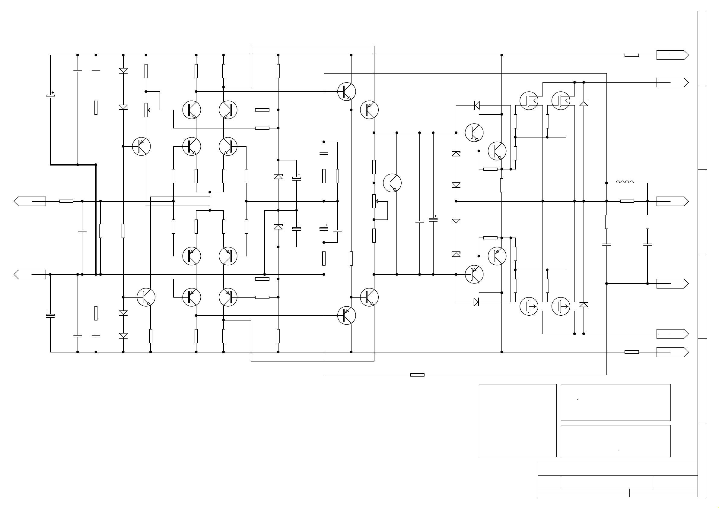
DIAGRAM SHOWS RA1000 OUTPUT
STAGE. RA2000 AND RA3000
OUTPUT STAGES DIFFER IN THE
NUMBER OF OUTPUT DEVICES PER
RAIL. THE RA2000 USES 4 DEVICES
PER RAIL AND THE RA3000 USES 6
DEVICES PER RAIL. ADDITIONAL
OUTPUT DEVICES ARE
CONFIGURED SIMILARLY WITH
560R GATE RESISTORS AS SHOWN.
Title
A3
Date: 1-Jul-1999 Sheet of
ON AMPLIFIERS WITH FLAT PACK
(J162 K1058) MOSFETS
FIT A 10pF >=250V WORKING
ACROSS THE GATE, DRAIN OF
QUIESCENT VOLTAGE ADJUSTMENT
THIS IS MEASURED ACROSS THE
GATE DRIVE AT POINTS A B
CHANNEL 1 AMPLIFIER
Number RevisionSize
A
3RAMAIN 2
62
Page 2
TO GIVE 300mV +/- 10mV
EACH K1058 MOSFET
C63
100NF/
100V
C62
OPT
D17
1N4148
R114
150R
R113
2K7
R111
680R
R109
82K
GATE RESISTORS R133 - R138
R145
22R
LABEL
HT+
LABEL
LT+2
F
100UF/100V
LABEL
LABEL
100UF/100V
AMP2
GND2
C66
C65
R88
C61
220PF
100NF/
250V
C52
1K
R103
OPT
1N4148
R100
39K
R85
OPT
C51
OPT
D18
Q44
BF423
R102
220K
Q43
BF422
D15
1N4148
D16
1N4148
VR4
470R
R84
330R
Q42
BF422
Q40
BC184L
R101
100R
R89
100R
Q38
BC214L
Q36
BF423
R92
100R
R93
100R
R83
2K7
R91
100R
R90
100R
R81
680R
Q41
BF422
Q39
BC184L
Q37
BC214L
Q35
BF423
R104
100R
R110
100R
R99
100R
R87
100R
R80 100R
R86
100R
Z11
6V2
Z10
6V2
R79
82K
C60
100UF/
16V
100UF
C54
100UF/
16V
C47
OPT
R76
OPT
C56
25V
/
Q34
BF422
100NF
R98
1K
Q31
BF423
R77
39K
C59
R97
220K
VR2
1K
R96
5K6
R95
1K5
Q33
BF423
Q32
BF422
Q28
BF422
C50
100NF
C55
100UF
Q30
BF422
Z8
D13
1N4148
D14
1N4148
Z9
Q26
BF423
D32
IN4004
D31
IN4004
Q29
BF422
R108
1K
R78
1K
Q27
BF423
R133
560R
R134
560R
A
R106
330R
R94
220R
R107
220R
B
R121
560R
GATE RESISTORS R121 - R126
R122
560R
D21
IN4004
D22
IN4004
CHOKE2
15 TURNS
R75
10R/2.5W
R74
10R/2.5W
C43
100NF/250V
R142
22R
LABEL
O/P2
R147
10R/2.5W
C44
100NF/250V
LABEL
GND
LABEL
LT-2
LABEL
HT-
E
D
C
R105
47R
DIAGRAM SHOWS RA1000 OUTPUT
STAGE. RA2000 AND RA3000
OUTPUT STAGES DIFFER IN THE
NUMBER OF OUTPUT DEVICES PER
RAIL. THE RA2000 USES 4 DEVICES
PER RAIL AND THE RA3000 USES 6
DEVICES PER RAIL. ADDITIONAL
OUTPUT DEVICES ARE
CONFIGURED SIMILARLY WITH
560R GATE RESISTORS AS SHOWN.
Title
A3
Date: 1-Jul-1999 Sheet of
ON AMPLIFIERS WITH FLAT PACK
(J162 K1058) MOSFETS
FIT A 10pF >=250V WORKING
ACROSS THE GATE, DRAIN OF
QUIESCENT VOLTAGE ADJUSTMENT
THIS IS MEASURED ACROSS THE
GATE DRIVE AT POINTS A B
CHANNEL 2 AMPLIFIER
Number RevisionSize
B
A
3RAMAIN 3
63
Page 3
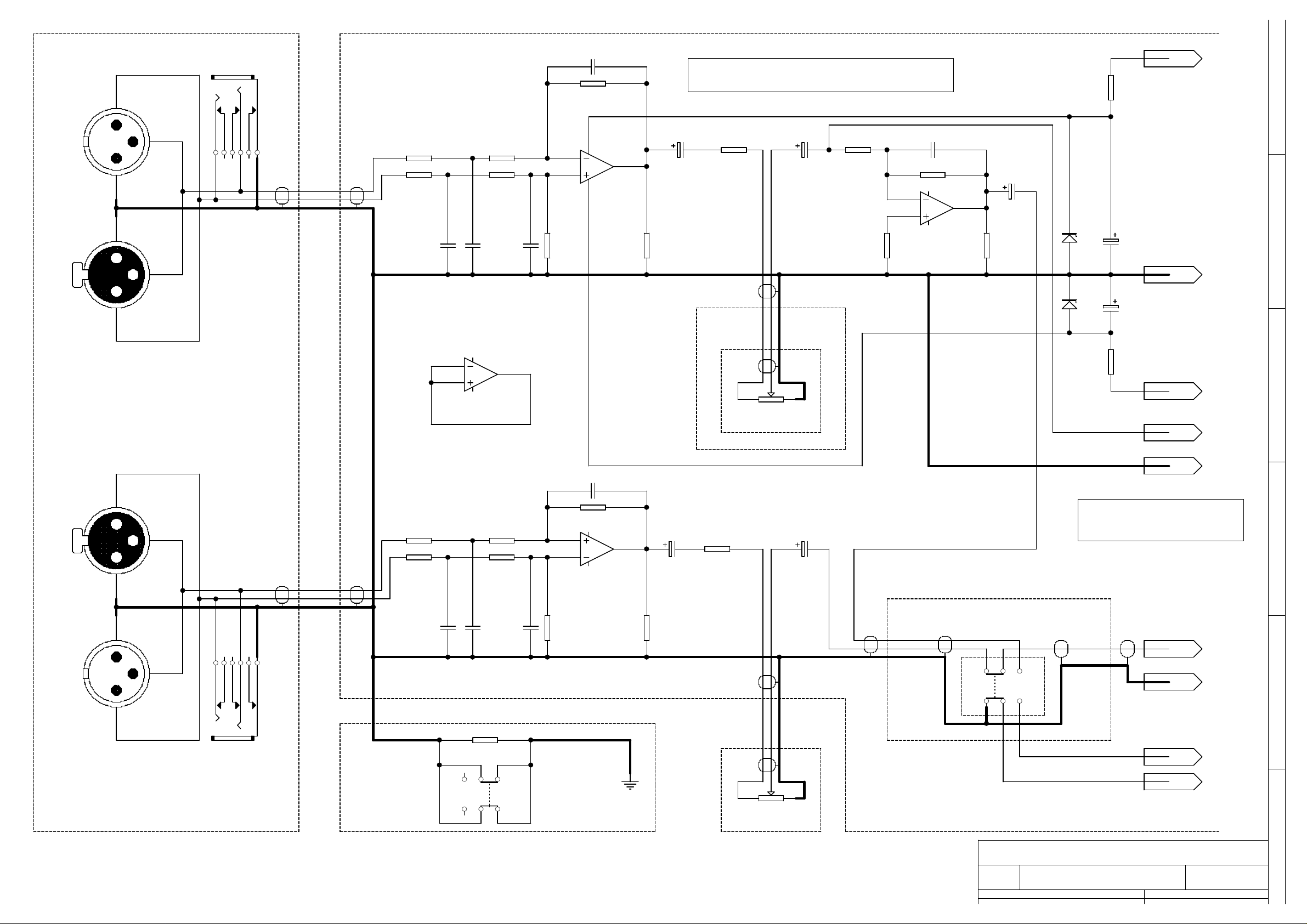
MC33079 IC IS FITTED TO POSITION IC1
RA1000/1 R10, R23 4K7/1W
XLR1
C7 10PF
LABEL
HT+
JACK1
NOTE:- FOR AMPS WITH FLAT PACK MOSFETS
1
R12 10K
R10
F
XLR2
4 11
IC1A
MC33079
1
3
R1 1K R2 9K1
2
BLUE
RED
SCR
COAX2SYMCOAX2SYM
2
3
R3 1K R4 9K1
10PF
220PF
C2
C1
220PF
C3
R5
10K
2
3
C6
100UF/16V
R6
100K
R7
1K
COAX2SYM
C4
100UF/16V
R9
100K
R13 100K
6
5
R8
47K
C9 10PF
IC1B
MC33079
7
C15
100UF/16V
R22
100K
Z1
18V
Z2
18V
C5
100UF/25V
LABEL
GND
C16
100UF/25V
E
1
RED
SCR
BLUE
9
10
SEE NOTE:-
IC1C
MC33079
COAX2SYM
8
VOL1
50K LIN
R23
LABEL
HT-
LABEL
AMP1
D
XLR3
XLR4
LABEL
GND1
C8 10PF
2
R14 10K
3
R15 1K
R16 1K
1
COAX2SYM COAX2SYM
BLUE
RED
SCR
1
C11
220PF
3
R17 9K1
R18 9K1
C12
10PF
C10
220PF
R19
10K
13
12
IC1D
MC33079
14
C13
100UF/16V
R20
100K
R21 1K
COAX2SYM
C14
100UF/16V
BRIDGE/STEREO
COAX2SYM COAX2SYM
RED
BLUE
SCR
MODE SWITCH
RA3000/1 R10, R23 6K8/1W
RA2000/1 R10, R23 6K8/1W
COAX1SYM COAX1SYM
RED
SCR
LABEL
AMP2
LABEL
GND2
C
SW2
B
2
RED
SCR
JACK2
RGND 10R/2.5W
GREENGREEN
BLUE
COAX2SYM
SW1
REDYELL
LABEL
LT+
LABEL
LEDBR
RA INPUT PCB
GROUND LINK
SWITCH
VOL2
50K LIN
Title
A3
INPUT STAGE CIRUITRY
Number RevisionSize
RAMAIN 1
Date: 1-Jul-1999 Sheet of
A
3
1 6
Page 4

240V 1.6A F 47R/23W
FAN
24V DC
GREEN/YELLOW
E
N L
IEC
BROWN
GREY
55C NORMALLY OPEN
CHASSIS
FUSE
THERMAL SWITCH
THERM1
RTHERM
220R/1W
BLACK
ORANGE
FRONT PANEL
MOUNTED MAINS
SWITCH
TRANSFORMER SECONDARY VOLTAGES
QUOTED VOLTAGES ARE OFF LOAD AC (RMS)
RA1000 RA2000 RA3000
REDRED
(4 OFF)
C81
47UF/35V
VOLTAGE FUSE1 SOFTSTART 100V 2A T
22R/23W
110V 2A T 22R/23W
BROWN
S1
220V 1.6A F 47R/23W
C82
47UF/35V
UNUSED VOLTAGE TAP
D33-D36
IN4004
SEE TRANSFORMER
WIRING DETAILS FOR
CORRECT CONNECTION
TX
0V
220V
AC:1
GREEN
AC:2
RED
CT
YELLOW
AC:3
ORANGE
RED 47 58 68
ORANGE 47 58 68
YELLOW 0 0 0
GREEN 52 63 73
BLUE 52 63 73
F
E
SOFTSTARTFUSE 1
240V
RA TRANSFORMER
AC:4
BLUE
BLACK
BLUE
YELLOW
MAINS INPUT VOLTAGE
SELECTOR. CONNECT
REQUIRED TRANSFORMER
VOLTAGE TAP.
9
LABEL
CON 5:1
LABEL
LABEL
LABEL
LABEL
LT+1
LT-1
HT+
LT+
FUSE2
FUSE1
RELAY3
C68
330NF/
250V
C67
330NF/
250V
2200UF/16V
RLY3 (A)
RLY3 (B)
C72
C71
C79
C70
C69
4
LABEL
5
LABEL
DBR1
KBPC3504
D23-D26
IN4004
(4 OFF)
D
C
LABEL
HT-
LABEL
LT+2
LABEL
LABEL
LT-2
2
STAR GND
FUSE3
FUSE4
C73
330NF/
250V
C74
330NF/
250V
C77
C78
2200UF/16V
C75
C76
C80
DBR2
KBPC3504
RA3000 C69, C70, C71, C72, C75, C76, C77, C78 4700UF/110V
RA2000 C69, C70, C71, C72, C75, C76, C77, C78 4700UF/110V
RA1000 C69, C70, C75, C76 4700UF/110V
C71, C72, C77, C78 NOT FITTED
Title
RA POWER SUPPLY
Number RevisionSize
A3
Date: 1-Jul-1999 Sheet of
RAMAIN 4
B
A
3
4 6
Page 5

R141
18K/1W
Q46
BF422
R151
10K
8
LABEL
2
LABEL
RLY3 (A)
RLY3 (B)
100NF/
250V
RELAY1RELAY2
C45C46
100NF/
250V
R152
10K
D12
IN4004
Q45
2SA958
R148
39K
R150
120R
Z12
5V6
IN4004
D30
R68
SEE NOTE
DMOD
IN4148
R67
47K
Q24
BF423
Z7
9V1
R66
47K
R69
24K
Q25
BF422
R154
100K
R70
18V
D27
IN4004
100uF
C40
R139
18k/2W
D11
1N4148
RMOD1
100K
Q20
BF422
R65
47K
Q21
BF423
Q23
BF422
Q22
BF422
D10 1N4148
TO AC:1
TO AC:4
3LABEL 4LABEL
TO LT+2
LABEL
D9 IN4004
R149
100K
5
F
THERM2
90C NORMALLY
CLOSED THERMAL
SWITCH
R62
100K
R64
47K
R63
47K
D8 IN4004
C38
100UF/16V
C39
100UF/16V
C37
680NF
D7
IN4004
LT +VE CH1
GND
BLUE BLUE
R61
4K7
CON 5
1
2
3
4
5
LT +VE CH2
INTERCONNECT
FLEXISTRIP
TO DISPLAY
LABEL
O/P1
LABEL
O/P2
E
D
1
2
3
4
5
6
6PIN
6PIN
6 WAY
FLEXISTRIP
INTERCONNECT
1
2
3
4
5
6
STATUS LED PCB
R140
8K2
LED1
POWER
RED
LED2
PROTECT
YELLOW
LED3
BRIDGE
GREEN
1
CH2 CH1
1
YELLOWGREYGREEN GREEN
LABEL
C
LEDBR
1
1
NOTE:
RA1000/1 RA2000/1 RA3000/1
R68= 330R/5W 1K/5W 1K/5W
Title
RA PROTECTION
Number RevisionSize
A3
Date: 1-Jul-1999 Sheet of
1RAMAIN 5
65
B
A
Page 6

LT +VE CH1
CH1 O/P
GND
CH2 O/P
LT +VE CH2
TO CON: 5
Q1
BF422
R5
510K
R4
10K
C2
1uF
Z14
11V
LED1
R14
C4
1
2
3
4
5
100NF
R11
10K
D3
1N4148
Q3
BF422
R13
10K
510K
C5
1uF
Z13
11V
SIGNAL PRESENT
Q4
BF423
-40dB
GREEN
R2
10K
1N4148
D1
C1
100NF
LED8
SIGNAL PRESENT
Q2
BF423
-40dB
GREEN
F
R12
100K
1N4148
R16
*
D4
C6
100NF
R17
1K
R26
*
R18
56K
R19
56K
Z2
18V/1.3W
*
R1
Q9
BC214L
R31
47R
9
7
SIG
8
R28
47K
Q10
BC214L
IC2
LB1443N
5
YELLOW
LED2
-20dB
Z5
9v1
Z6
8
1
2
3
4
6
Z8
2V7
Z7
4v7
LED3
-12dB
LED4
-7dB
LED5
-4dB
LED6
0dB
R3
100K
D2
1N4148
R7
*
100NF
C3
R8
1K
R9
56K
R10
56K
Z1
18V/1.3W
7
SIG
9
8
Q11
BC214L
R32
47R
IC3
LB1443N
5
Q12
BC214L
Z9
9v1
1
2
3
4
6
Z10
6v8
Z11
4v7
Z12
2V7
R29
47K
YELLOW
LED9
-20dB
LED10
-12dB
LED11
-7dB
LED12
-4dB
LED13
0dB
E
D
C
RA4001 R1, R26 2K2/4W
R7, R16 5K1
R27, R30 100K
Z3, Z4 10V
RA3001 R1, R26 3K3/4W
R7, R16 6K8
R27, R30 (NOT FITTED) Z3, Z4 6V2
RA2001 R1, R26 3K3/4W
R7, R16 8K2
R27, R30 (NOT FITTED)
Z3, Z4 6V2
RA1001 R1, R26 2K2/4W
R7, R16 13K
R27, R30 (NOT FITTED
Z3, Z4 7V5
R25
100K
Z4
*
R27
ONLY FIT
ON RA4001
D6
1N4148
Q7
BF423
R24
100K
C8
470PF
C10
47UF/35V
Q8
BF423
R23
4K7/1W
LED7
CLIP
RED
R22
100K
Z3
*
D5
1N4148
R30
ONLY FIT
ON RA4001
Q5
BF423
C7
470PF
C9
47UF/35V
R21
100K
Title
Number RevisionSize
A3
Date: 1-Jul-1999 Sheet of
Q6
BF423
R20
4K7/1W
CLIP
LED14
RED
RA DISPLAY CARD
B
A
3RA DISPLAY
66
Page 7

R7, R16 13K
LT +VE CH1
CH1 O/P
GND
CH2 O/P
LT +VE CH2
TO CON: 5
100K
1
2
3
4
5
R12
1N4148
R16
D4
R17
1K
C6
100NF
R18
56K
R19
56K
D3
1N4148
7
Z2
20V/1.3W
SIG
100NF
R11
10K
C4
Q3
BF422
R26
8
1
R13
10K
IC2
U257
R14
510K
LED1
SIGNAL PRESENT
-40dB
GREEN
100NF
C1
R5
510K
LED8
SIGNAL PRESENT
-40dB
GREEN
F
R15
1K
Q4
BF423
R2
Q1
BF422
R4
10K
R6
1K
Q2
BF423
10K
C5
470NF
1N4148
D1
C2
470NF
E
YELLOWYELLOW
LED2
-20dB
R3
100K
LED9
-20dB
R1
D2
LED3
-12dB
6
P0
5
P1
4
P2
3
P3
2
P4
LED4
-7dB
-4dB
1N4148
R7
LED5
R8
1K
100NF
C3
R9
56K
R10
56K
LED10
IC3
8
U257
6
7
SIG
P0
5
P1
4
P2
3
P3
2
P4
LED11
LED12
-12dB
-7dB
-4dB
D
1
Z1
LED6
20V/1.3W
0dB
LED13
0dB
RA3000 R1, R26 3K3/4W
R7, R16 6K8
Z3, Z4 6V2
RA2000 R1, R26 3K3/4W
R7, R16 8K2
Z3, Z4 6V2
RA1000 R1, R26 2K2/4W
R25
100K
Q7
BF423
D6
1N4148 C8
470PF
C10
47UF/35V
R24
100K
Z4
Q8
BF423
R23
4K7/1W
LED7
CLIP
RED
R22
100K
D5
1N4148
Z3
Q5
BF423
Q6
BF423
C7
R21
100K
470PF
C9
47UF/35V
Title
A3
R20
4K7/1W
CLIP
LED14
RED
RA DISPLAY CARD
Number RevisionSize
RA DISPLAY 3
Date: 1-Jul-1999 Sheet of
C
B
A
6 6
Page 8

1
2
3
4
CON
R87
1k
CON
R3
5k6
D1
In4004
R1
8k2
R2
82k
TR1
BC184L
D16
10v
D2
IN4004
R5
8k2
C3
6n8
C1
6n8
R6
82k
R4
1k
R7
1k
D3
IN4148
CON
D4
IN4148
D17
10v
TR2
BC214L
R8
5k6
CON
CON CON
Title
ION PCBRE-ENTRANT PROTECT
Number RevisionSize
A4
PCB1042/P1
Date: 22-Jul-1999 Sheet of
File: D:\PROTEL\RANEW\REENTRY.S01 Drawn By:
1 1
L BASHAM
Page 9

Protection System
The protection system is based around Q20-Q25. Under normal conditions Q20 – Q23 will be
off. At turn-on C40 will charge through R65 towards the +LT supply rail. The voltage is fed to the
base of Q25 via D11. When the voltage acros s C40 reach es approximately 10V Q2 5 will turn on
and thus turn on Q24. Resisto r/diode network R67 & D38 conn ected betwe en Q24 collector and
Q25 base provides positive feed back in order to make the turn-on/turn-off of Q24 more define d.
The collector of Q24 is connected via R68 R150 & Q45 to the coils of relays RLY1-3.
Transistors Q20 and Q21 are connected in such a way that a voltage of -650mV applied to the
emitter of Q20 will turn on Q20 and hence Q21. This will rapidly discharge C40 and hence turn
off Q25 and Q24 thus opening the output relays. Similarly Q23 is c onnected such that a base
voltage of +650mV will turn it, and hence Q22, on with the same resultant opening of the output
relays.
The output of each channel is fed via resistors R63 and R 64 into C38-C39 and then via D9 and
D10 to Q23 base an d Q20 emitter respectively. The combination of C3 8-C39 with R63 and R64
forms a low-pass filter, and so at signal frequencies C38-C39 will have no voltage across it. In
the event of a DC offset appearing at the output, however, C38-C39 will charge to a DC voltage,
turning on Q23 & Q22 or Q20 & Q21 de pending upon the pola rity, and hence opening the output
relays.
The Network consisting of R62, R61 and C37 provide the rapid tur n-off feature of the protection
system. R61 is connected through the 90 degree thermal switch to D37 and D7, which are
connected to the secondaries of the mains transformer. The union of D37 and D7 will, therefore,
show a full-wave rectified version of the secondary voltage. This is averaged by C37 to a
negative DC voltage, reverse biasing D8 and, therefore, having no effect on the protection
system. Should one of the thermal switches open, or the power be turned off, C37 will be rapidly
charged towards the +LT rail via R61, forwar d bias ing D8, tu rning Q23 on and open ing the output
relays. If there is no rapid turn off, suspect R62 (1 00k) this may be open circ uit. It is worth noting
that failure of this resistor will render the thermal shutdown useless.
 Loading...