

Page 1
Insulated
Hand-lift Cabinet
Rev. 38 (4/13) Page 1 of 4
FL-0520
5925 Heisley Road • Mentor, OH 44060-1833
OPERATING and MAINTENANCE INSTRUCTIONS
For INSULATED HAND-LIFT CABINETS; MODEL H-339 “C” SERIES
ELECTRICAL SPECIFICATIONS:
MODEL Volts Watts Amps Hertz Phase NEMA
H-339 -128C, 188C,
12-188C, 1813-C,
UA-8C, 12-135C
H-339- 128C-240, 188C-240,
12-188C-240, 1813C-240,
UA-8C-240, 12-135C
Above model numbers may include letters: M, L, P, S, SS or Z.
120 900 7.5 60 1 5-15
240 900 3.8 60 1 6-15
FIGURE 1 FIGURE 2
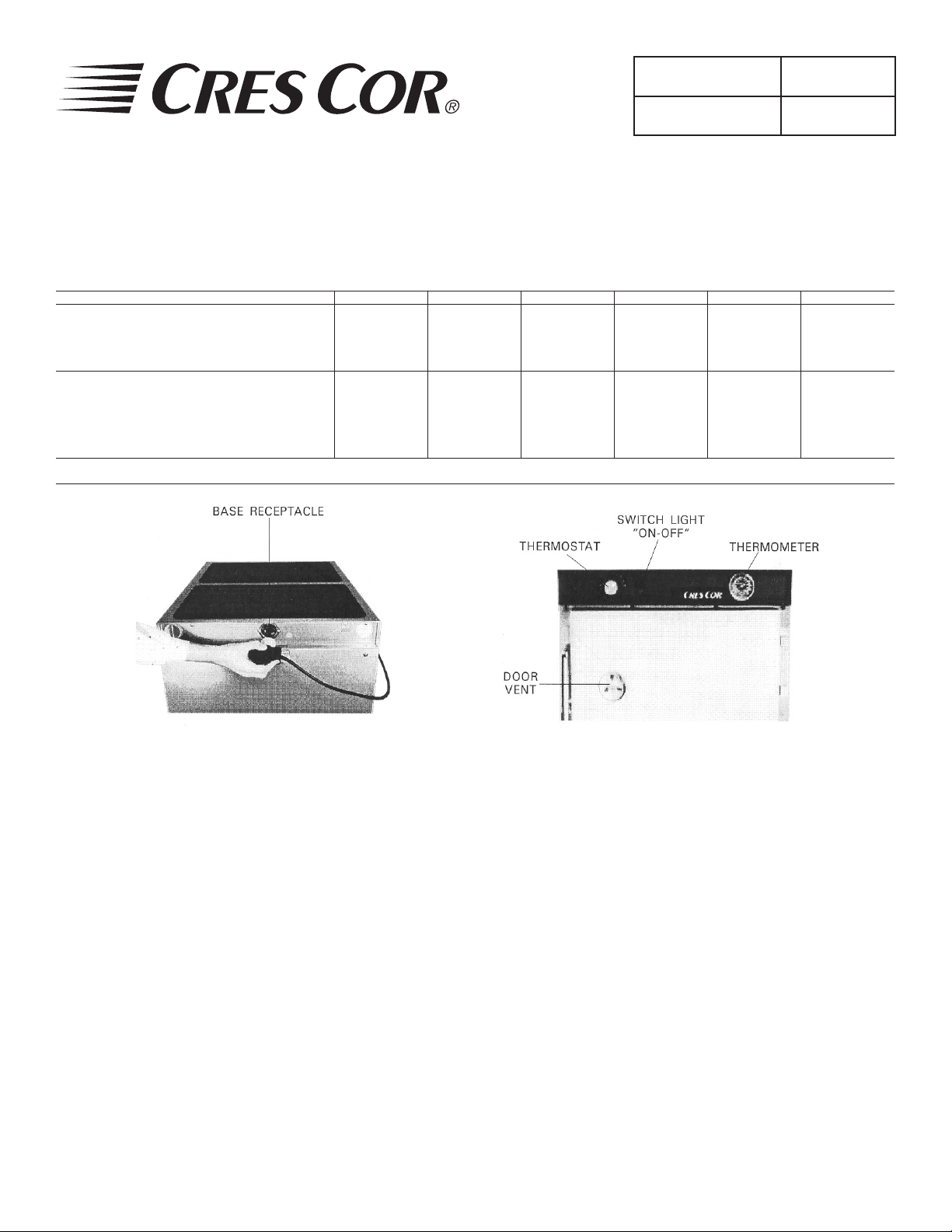
HOW TO INSTALL UNIT: (Figure 1)
1. Plug cord into receptacle in back of the unit.
2. Turn plug clockwise to lock.
3. Plug other end into 15-amp wall outlet.
4. Place cabinet in a well ventilated area.
5. Push the switch on, turn the thermostat to No. 10
and run the unit for one hour.
NOTE: DO NOT PUT IN FOOD! This step is to
burn off manufacturing oils and excessive
adhesive.
6. Let the cabinet cool and wipe inside clean with
detergent and hot water before use.
Call Toll-free: 877-CRES COR (273-7267) • Fax: 800-822-0393 • www.crescor.com
HOW TO OPERATE UNIT: (Figure 2)
1. Push switch “ON”. Yellow light will come on.
2. Turn thermostat to the temperature you need.
NOTE: No. 7½ setting will give you about 180° F
(82°C). Proper food holding temperature is
140° F (60°C) or higher.
3. Preheat cabinet for 45 minutes
4. Put food into cabinet.
5. Turn the wing nut on the door vent to open the vent
when less humidity is needed.
To Turn Off Unit:
Push switch “OFF”. The yellow light will go off.
NOTE: Optional digital thermometer will ash if cabinet
temperature is below 140°F or above 250°F.
Call the factory if you need different settings.
Page 2
Insulated
WARNING
Hand-lift Cabinet
Rev. 38 (4/13) Page 2 of 4
FL-0520
5925 Heisley Road • Mentor, OH 44060-1833
OPERATING and MAINTENANCE INSTRUCTIONS
For INSULATED HAND-LIFT CABINETS; MODEL H-339 “C” SERIES
Hints:
BEFORE CLEANING CABINET:
1. Remove Power Cord from cabinet.
2. Do NOT hose cabinet with water.
3. Do NOT get water on controls.
4. Do NOT use abrasives or harsh
chemicals.
HOW TO CLEAN UNIT:
SOIL CLEANER METHOD
DIRT
CABINET
Inside and
Outside
FINGERPRINTS,
GREASE OIL
Mild detergent* and hot water,
or mild abrasive cleaner.
Steam (no strong alkaline
additive)
Detergent* and hot water.
Chemical oven cleaner.
Mild abrasive cleaner.
Oily or waxy cleaner.
1. Wipe up spills as soon as possible.
2. Clean cabinet regularly to avoid heavy dirt build-up.
3. Make a test spot with cleaner.
4. Follow manufacturer’s directions on cleaner.
5. Do not mix cleaners
6. Avoid drips and splashes.
7. Do not use Cres Clean on plastics and labels.
1. Use soft, damp cloth.
2. Rinse with hot water.
3. Wipe dry.
1. Rinse after steam cleaning.
2. Wipe dry.
1. Wipe with soft, damp cloth.
2. Rinse with hot water.
3. Wipe dry.
Follow oven cleaner manufacturer’s
directions.
Apply with soft, clean cloth.
WATER SPOTS Mild abrasive cleaner. Wipe with damp cloth.
* Mild detergents include soaps and non-abrasive cleaners
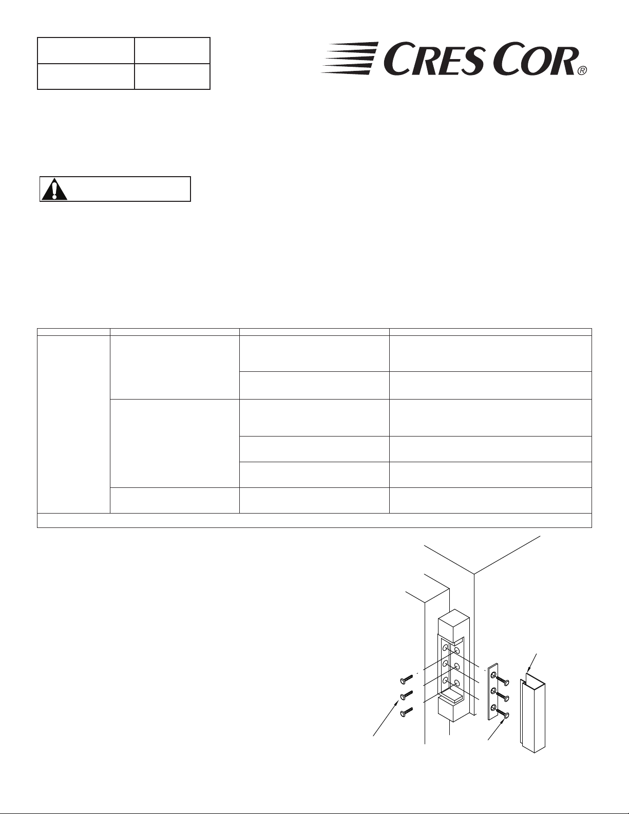
HOW TO REVERSE DOOR HARDWARE
FOR OPPOSITE HAND (Refer to Fig. 3 [hinge]):
1. Pop off hinge covers with screwdriver.
2. Remove screws from hinges to cabinet; remove door
and unscrew latch strike from cabinet.
3. Remove hinges, latch and all remaining screws from
the right and left side of door. Keep all screws.
4. Re-mount hinges and latch in the same hole pattern on
the opposite sides of the door. Plug all extra holes with
screws.
5. Remove all screws from the front sides of cabinet (not
the top and bottom).
6. Hold door up to cabinet and screw hinges to the
cabinet.
7. Open door and re-mount the latch strike to cabinet.
8. Plug all extra holes with screws and snap on the hinge
covers.
Call Toll-free: 877-CRES COR (273-7267) • Fax: 800-822-0393 • www.crescor.com
C'SK SCREWS
#10-24 X 3/4"
DOOR
TOP
FIGURE 3
CABINET
BODY
SCREWS-T.H.M
#10-24 X 1/2"
HINGE
COVER
Page 3

Insulated
Hand-lift Cabinet
Rev. 38 (4/13) Page 3 of 4
FL-0520
5925 Heisley Road • Mentor, OH 44060-1833
OPERATING and MAINTENANCE INSTRUCTIONS
For INSULATED HAND-LIFT CABINETS; MODEL H-339 “C” SERIES
HOW TO ADJUST THE DOOR LATCH:
1. For vertical adjustment
(Up and down movement):
a. Loosen (2) screws located in magnetic
strike on cabinet.
b. Move strike up or down for alignment
to magnet on latch.
c. Tighten screws to secure
2. For horizontal adjustment
(Greater or lesser magnetic draw):
a. Loosen four (4) screws in latch on door.
b. Move latch forward or backward to
adjust magnetic draw.
c. Tighten screws to secure.
TROUBLE-SHOOTING CHART
FAILURE POSSIBLE CAUSE/CHECK
1. Unit does not heat: 1a. Thermostat turned up.
1b. Switch is “ON”.
1c. Cord is plugged into outlet.
1d. Circuit breaker/fuse for
wall outlet
2. Unit will not turn off: 2a. Thermostat turned down.
2b. Switch is “OFF”
If cause is none of the above, refer to our list of
authorized service agencies, FL-1400.
REPLACEMENT PARTS
120V 240V
Cabinet Receptacle ...............0713-011 ...............0713-012
Cord Set ...............................0810-149-01-K .....0810-150-01
H-339-12-135C ONLY ........0810-029 ...............0810-039
Switch ..................................0808-113-K ...........0808-113-01-K
Heater Kit ............................. 0811-066-K ...........0811-066-1K
Thermostat ...........................0848-008-ACK ..... 0848-008-ACK
Thermostat (before 2011) .....0848-008-ACK-1 ..0848-008-ACK-1
Terminal Block ..................... 0852-091 ...............0852-091
Thermometer ........................ 5238-030-K ...........5238-030-K
Door Latch Kit ..................... 1006-122-01-K .....1006-122-01-K
H-339-12-135C ONLY ........1006-142-01-K .....1006-142-01-K
Strike Kit .............................. 1006-122-02-K .....1006-122-02-K
H-339-12-135C ONLY ........1006-142-02-K .....1006-142-02-K
Hinge Kit ..............................0519-074-K ........... 0519-074-K
Gasket Kit ............................0861-077 ............... 0861-077
Casters .................................. 0569-306-K ...........0569-306-K
Casters w/Brake ...................0569-306-BK ........ 0569-306-BK
Legs (H-339-12-135C) .........1206-025 ............... 1206-025
Transport Latch Kit ..............1246-025-K ........... 1246-025-K
KIT NUMBERS FOR H-339 MODELS
Description -UA-8C -12-135C -128C -188C 12-188C -1813C
Door Kit 5508-085-K* 5508-087-K* 5508-083-K* 5508-084-K* 5508-084-K* 5508-084-K*
Rack Insert 0621-281-K 1104-085-K 1170-129 1170-130 1170-122 1137-130-03
*Add Sufx “SS-K” for stainless steel door.
Call Toll-free: 877-CRES COR (273-7267) • Fax: 800-822-0393 • www.crescor.com
Page 4

Insulated
Hand-lift Cabinet
FL-0520
Rev. 38 (4/13) Page 4 of 4
5925 Heisley Road • Mentor, OH 44060-1833
OPERATING and MAINTENANCE INSTRUCTIONS
For INSULATED HAND-LIFT CABINETS; MODEL H-339 “C” SERIES
* WIRE # 13 GROUND
TO INNER BODY
& H339-CGM SERIES ONLY
FOR H33912135C, H339X
*
13
*
13
*
16
*
16
SLEEVING (12-PLACES)
6-15P
G
2
1
5-15P
G
W
2
1
>
>
12
L6-15P
X
Y
2
1
>
>
17
12
L5-15P
W
<
1
2
1
>
>
<
2
S.W.
A
4 5 6 7 8 9 10
TCB
TB TERMINAL BLOCK
SW SWITCH-POWER (LIGHTED)
S SENSOR-AIR
L6-15P FLANGED INLET,250V. 15A.
L5-15P FLANGED INLET,120V. 15A.
H2&3 HEATER-RIGHT & LEFT SIDE
TCB THERMOSTAT
H1 HEATER-BOTTOM
ITEM
DESCRIPTION
LEGEND
S
t
o
3
6
8
4
5
4
6
5
>
*NOTE "A"
FOR 120 V.: ATTACH WIRE #5 TO TERMINAL #9
FOR 240 V.: ATTACH WIRE #5 TO TERMINAL #10
ADD WIRE NUT TO UNUSED LEAD
3
8
240V
OPTIONAL
t°
110V/220V
*
TRANSFORMER
SENSOR
120V
**
51
DIGITAL THERMOMETER
*
50
110V/220V
TRANSFORMER
342
1
5
OPTIONAL
14
8
t°
SENSOR
12
10
**
51
50
52
4
231
8
5
OPTIONAL
11
TB
9
7
H1
H2
H3
Call Toll-free: 877-CRES COR (273-7267) • Fax: 800-822-0393 • www.crescor.com
 Loading...