

Page 1
5925 Heisley Road • Mentor, OH 44060-1833
OPERATING and MAINTENANCE INSTRUCTIONS
MODEL: H339127LJ & H339127PLJ (PASS THRU)
BROILED HOLDING UNIT FOR LONG JOHN SILVER’S
ELECTRICAL SPECIFICATIONS:
MODEL Volts Watts Amps Hertz Phase NEMA
Insulated
Holding Cabinet
Rev. 1 (10/08) Page 1 of 4
FL-0520-7
H-339-127-LJ
H-339-127-PLJ
120 900 7.5 60 1 5-15
Models are designed for AC service.
Base Receptacle
FIGURE 1
Thermostat
Switch-Light
ON/OFF
FIGURE 2
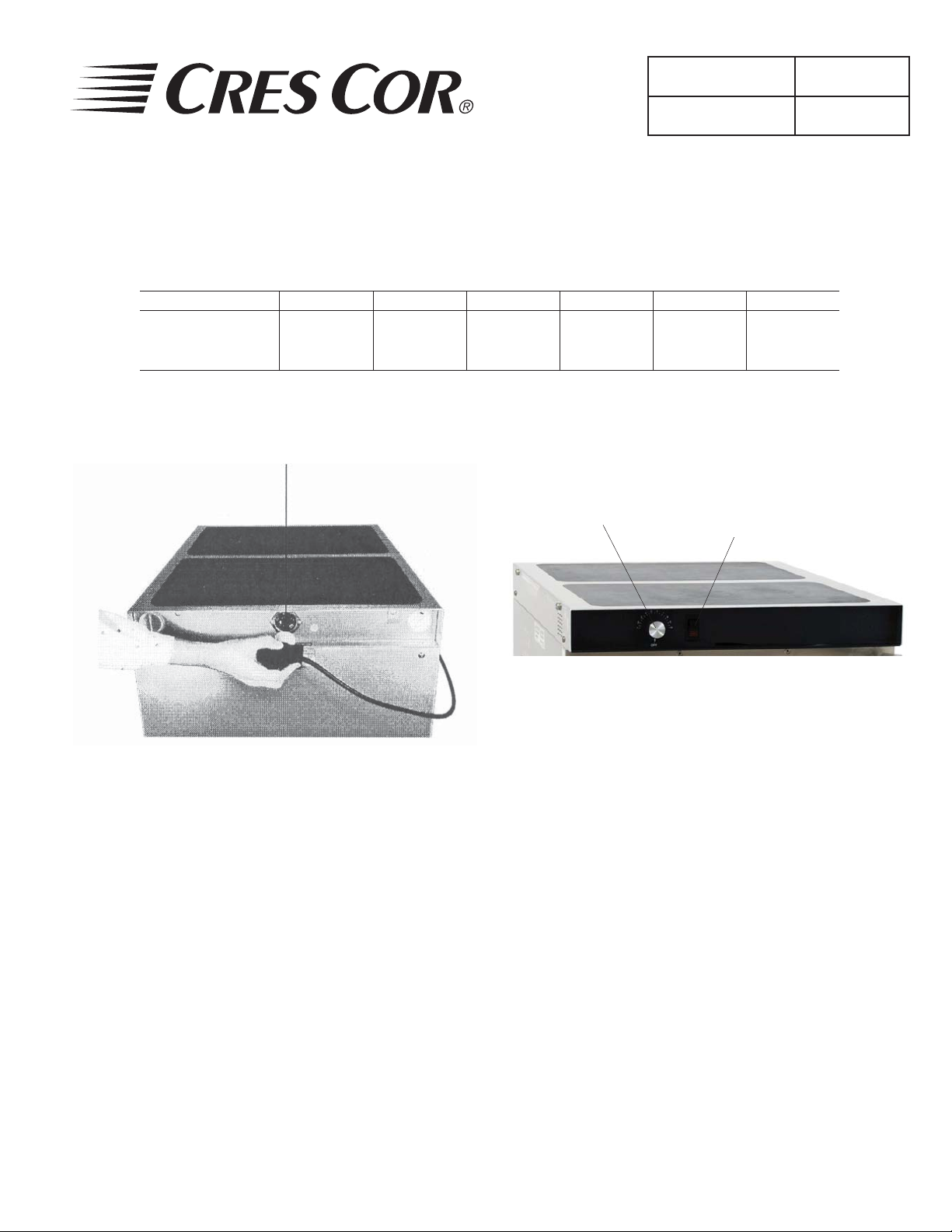
HOW TO INSTALL UNIT: (Figure 1)
Plug cord into receptacle in back of unit. 1.
(Side of unit for H339127PLJ)
Turn plug clockwise to lock.2.
Plug other end into 15 amp. wall outlet.3.
Place cabinet in a well ventilated area.4.
Push the switch on, turn the thermostat to No. 10 5.
and run the unit for one hour.
NOTE: DO NOT PUT IN FOOD! This step is to
burn off manufacturing oils and excessive
adhesive.
Let the cabinet cool and wipe inside clean with 6.
detergent and hot water before use.
Call Toll-free: 877-CRES COR (273-7267) • Fax: 800-822-0393 • www.crescor.com
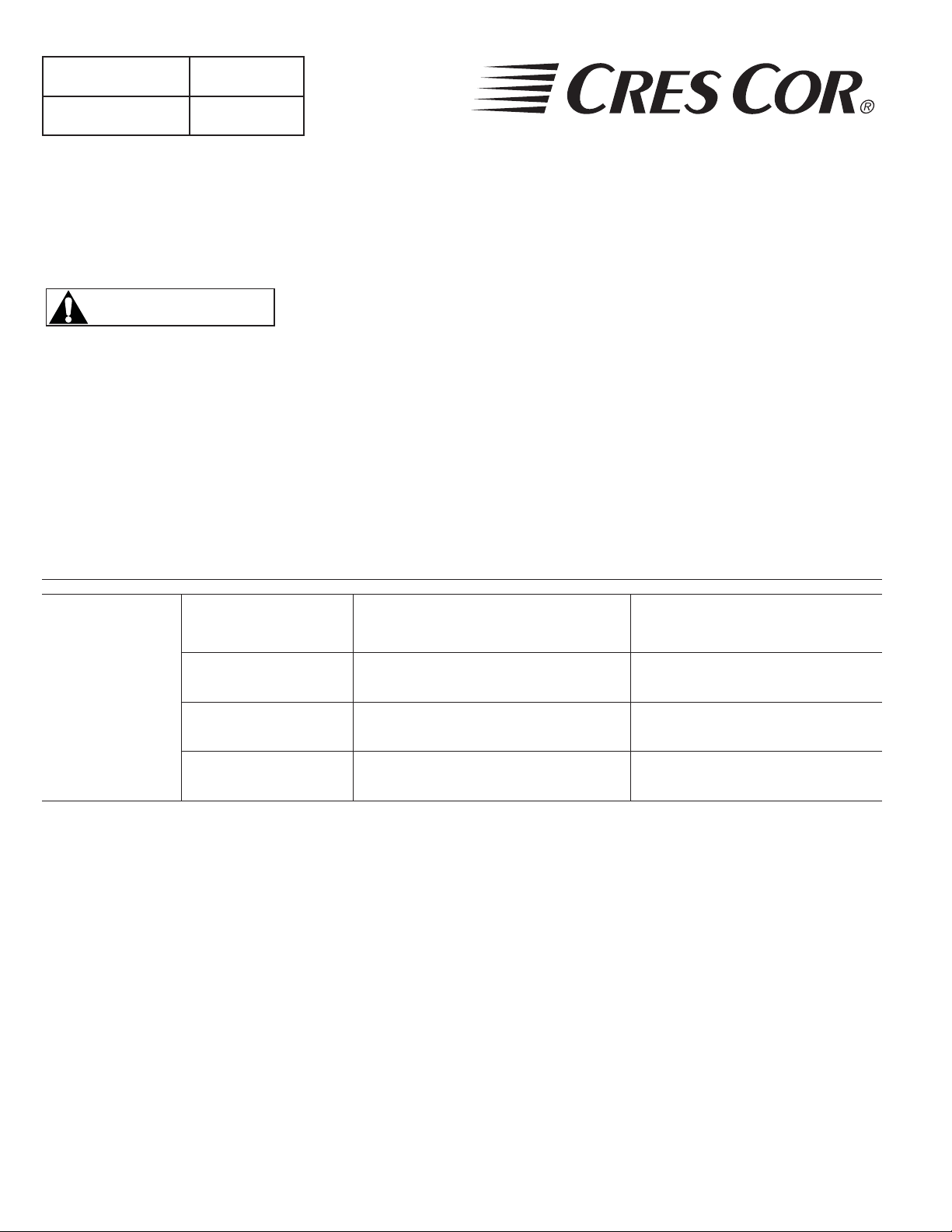
HOW TO OPERATE UNIT: (Figure 2)
Push switch “ON”. Yellow light will come on.1.
Turn thermostat to the temperature you need.2.
NOTE: No. 7½ setting will give you about 180° F.
Proper food holding temperature is 140° F or
higher.
3. Preheat cabinet for 45 minutes
4. Put food into cabinet.
To Turn Off Unit:
Push switch “OFF”. The yellow light will go off.
NOTE: Thermometer in the front door gives the
inside cabinet temperature.
Page 2
Insulated
Holding Cabinet
Rev. 1 (10/08) Page 2 of 4
FL-0520-7
OPERATING and MAINTENANCE INSTRUCTIONS
MODEL: H339127LJ & H339127PLJ (PASS THRU)
BROILED HOLDING UNIT FOR LONG JOHN SILVER’S
WARNING
5925 Heisley Road • Mentor, OH 44060-1833
BEFORE CLEANING CABINET:
1. Unplug power cord from wall.
2. Do NOT hose cabinet with water.
3. Do NOT get water on controls.
4. Do NOT use abrasives or harsh
chemicals.
HOW TO CLEAN UNIT:
SOIL CLEANER METHOD
ROUTINE CLEANING
CABINET
STUBBORN SPOTS
Inside and Outside
(Stainless Steel)
AND STAINS
BURNT-ON FOODS
OR GREASE
HARD WATER
SPOTS and SCALE
* Mild detergents include soaps and non-abrasive cleaners
Hints:
Wipe up spills as soon as possible. 1.
Clean cabinet regularly to avoid heavy dirt build-up.2.
Make a test spot with cleaner.3.
Follow manufacturer’s directions on cleaner.4.
Do not mix cleaners.5.
Avoid drips and splashes.6.
Soap, Ammonia, or mild* detergent
and water
Mild abrasive made for stainless steel
Chemical oven cleaner for stainless
steel
Vinegar
1. Sponge on with cloth.
2. Rinse with water.
3. Wipe dry.
1. Apply with damp sponge or cloth.
2. Rub lightly.
Follow oven cleaner
manufacturer’s directions.
1. Swab or wipe with cloth.
2. Rinse and dry.
TROUBLE-SHOOTING CHART
FAILURE POSSIBLE CAUSE/CHECK
1. Unit does not heat: 1a. Thermostat turned up.
1b. Switch is “ON”.
1c. Cord is plugged into cabinet.
1d. Cord is plugged into outlet.
1e. Circuit breaker/fuse for
wall outlet.
2. Unit will not turn off: 2a. Thermostat turned down.
2b. Switch is “OFF”
If cause is none of the above, refer to our list of
authorized service agencies, FL-1400.
Instructions for replacing parts are included in
replacement parts kits.
Call Toll-free: 877-CRES COR (273-7267) • Fax: 800-822-0393 • www.crescor.com
REPLACEMENT PARTS
Cabinet Receptacle 0713-011
Cord Set 0810-031-1
Switch 0808-103
Heater Kit 0811-066-K
Thermostat Kit 0848-008-ACK
Terminal Block 0852-008
Door Latch Kit 1006-142-K1
Strike Kit 1006-142-01-K
Hinge Kit 6507-005
Thermometer Kit 5238-008-K
Gasket Kit 0861-077
Door Kit (w/Thermometer) H339037-15-K
Door Kit (w/o Thermometer) H339037-41-K
Rack Insert H339037-28
Pan Support Frame H339031-33
Page 3

5925 Heisley Road • Mentor, OH 44060-1833
OPERATING and MAINTENANCE INSTRUCTIONS
MODEL: H339127LJ & H339127PLJ (PASS THRU)
BROILED HOLDING UNIT FOR LONG JOHN SILVER’S
HOW TO REVERSE DOOR HARDWARE
FOR OPPOSITE HAND
(Refer to Figure 3 [hinge] and Figure 4 [latch]):
Remove hinge covers with a screwdriver.1.
Remove screws from hinges to door (Item 1) and hinge 2.
brackets to cabinet (Item 2).
Remove screws from latch to door (Item 3) and latch 3.
bracket to cabinet.
NOTE: Keep hinges and latch strike mounted to the
brackets.
Remove all remaining screws from both sides of 4.
door and cabinet in that area. Keep all screws.
Turn latch strike bracket 180° and mount it to 5.
the opposite side of the cabinet with the same
screws you removed. Do the same with the hinge
brackets.
Line up (4) latch holes to door holes on the 6.
opposite side of the door. Mount latch with same
screws that were removed.
Mount hinges to the opposite side of the door and 7.
snap on the hinge covers.
Plug remaining holes with screws.8.
HOW TO ADJUST THE DOOR LATCH:
(Refer to Figure 4)
DOOR
TOP
Insulated
Holding Cabinet
Rev. 1 (10/08) Page 3 of 4
HINGE
BRACKET
SCREW
#10-24 X 1/2"
SCREW
1
#10-24 X 1"
FIGURE 3
FL-0520-7
2
HINGE
COVER
SCREW, FLAT HEAD
#10-24 X 1-1/2” LONG
For vertical adjustment (up and down movement):1.
a. Loosen (2) screws located in magnetic strike
attached to bracket on cabinet.
b. Move strike up or down for alignment to magnet
on latch.
c. Tighten screws to secure.
For horizontal adjustment (greater or lesser 2.
magnetic draw):
a. Loosen (4) screws in door latch.
b. Move latch forward or backward to adjust
magnetic draw.
c. Tighten screws to secure.
Call Toll-free: 877-CRES COR (273-7267) • Fax: 800-822-0393 • www.crescor.com
LATCH STRIKE
BRACKET
FIGURE 4
Page 4

Insulated
Holding Cabinet
Rev. 1 (10/08) Page 4 of 4
FL-0520-7
OPERATING and MAINTENANCE INSTRUCTIONS
MODEL: H339127LJ & H339127PLJ (PASS THRU)
BROILED HOLDING UNIT FOR LONG JOHN SILVER’S
5925 Heisley Road • Mentor, OH 44060-1833
WIRING DIAGRAM
TB
*
16
*
16
*
WIRE #16 GROUND
G
15
15
G
TO INNER BODY
LEGEND
ITEM DESCRIPTION
1.
H1
2.
H2 & 3
3.
L5-15P
4.
L6-15P
5.
S
6.
SW
7.
TB
8.
TCB
9.
10.
J
W
L5-15P
Y
X
L6-15P
1
2
2
SW
A
1
1
2
17
TCB
HEATER - BOTTOM
HEATER - RIGHT AND LEFT SIDE
FLANGED INLET, 120V. 15A.
FLANGED INLET, 250V. 15A.
SENSOR - AIR
SWITCH - POWER (LIGHTED)
TERMINAL BLOCK
TEMPERATURE CONTROL BOARD
SLEEVING 4-PLACES
JUMPER #807-107
3
3
5
J
4
8
J
6
65
t°
*SEE NOTE "A"
84
45678910
9
11
10
H1 H2 H3
12
NOTE "A"
FOR 120V., ATTACH
WIRE #5 TO TERMINAL #9
FOR 250V., ATTACH
WIRE #5 TO TERMINAL #10
7
14
Call Toll-free: 877-CRES COR (273-7267) • Fax: 800-822-0393 • www.crescor.com
 Loading...