

Cres Cor CC-2222C-PR, CC-2222C-PL, CC-2222C-PRL, CC-2222C-PR-2, CC-2222C-PL-2 Service Manual
...Page 1

Hot Cabinet
FL-1917-KFC-M
5925 Heisley Road • Mentor, OH 44060-1833
INSTALLATION, OPERATION and MAINTENANCE MANUAL
for Cres Cor Models:
CC-2222C-PR, CC-2222C-PL, CC-2222C-PRL,
CC-2222C-PR-2, CC-2222C-PL-2, and CC-2222C-PRL-2
Rev. 14 (10/08)
Page 1 of 16
Call Toll-free: 877-CRES COR (273-7267) • Fax: 800-822-0393 • www.crescor.com
Page 2

Hot Cabinet
FL-1917-KFC-M
Rev. 14 (10/08)
Page 2 of 16
5925 Heisley Road • Mentor, OH 44060-1833
TABLE OF CONTENTS
SUBJECT PAGE
INST ALLA TION INSTRUCTIONS............................................................................3
OPERA TING INSTRUCTIONS..................................................................................4
MAINTENANCE INSTRUCTIONS
How to Clean the Unit........................................................................................5
Maintenance........................................................................................................6, 7
Latch Adjustment................................................................................................6
Trouble Shooting Guide.....................................................................................7
Replacement Parts (Cabinet)...............................................................................8, 9, 10, 11
Replacement Parts (Hot Unit).............................................................................12, 13, 14
Wiring Diagrams................................................................................................ 15, 16
ELECTRICAL DATA SHEET.....................................................................................FL-1484-A
SERVICE POLICY and AGENCY LIST.....................................................................FL-1400
WARNING
RISK OF FIRE OR ELECTRIC SHOCK
WARNING: TO REDUCE THE RISK OF FIRE OR ELECTRIC SHOCK,
DO NOT REMOVE COVER (OR BACK)
NO USER-SERVICEABLE PARTS INSIDE
DO NOT OPEN
REPAIR SHOULD BE DONE BY AUTHORIZED SERVICE
Call Toll-free: 877-CRES COR (273-7267) • Fax: 800-822-0393 • www.crescor.com
PERSONNEL ONLY
Page 3

Hot Cabinet
FL-1917-KFC-M
5925 Heisley Road • Mentor, OH 44060-1833
INSTALLATION INSTRUCTIONS
GENERAL SPECIFICATIONS:
Net Weight: 355 Lbx. (Includes Hot Cabinet)
Dimensions: 24-15/16” W x 33-15/16” D x 77” H
Casters: 5” Dia. Swivel-type (All 4 casters equipped
with brakes.)
Capacity: Fifteen (15) 18” x 26” pans on 3-5/8” spacing.
ELECTRICAL SPECIFICATIONS:
Model No. Hot Unit Volts Watts Amps Phase Cycle Service
CC-2222C-PR
CC-2222C-PL
CC-2222C-PRL
CC-2222C-PR-2
CC-2222C-PL-2
CC-2222C-PRL-2
INSTALLATION OF OPTIONAL TWIST-LOCK
PLUG: (NEMA L5-20) P/N 0840-036
Cut molded plug off end of power supply cord (Item 42).1.
Remove cover from plug body by loosening three 2.
screws on face of plug.
Strip jacket from cord approximately 1-1/2”.3.
Strip individual wires per strip gage found on rear of 4.
plug body.
Slide plug cover over cord.5.
Connect individual wires to plug body. Make sure color 6.
code is followed (i.e. green to green, white to white;
colored to colored).
Pull plug cover over plug body and fasten with screws 7.
on face of plug.
Insure cord clamp on rear of plug is over cord jacket. 8.
Tighten cord clamp.
FIELD-REVERSING CABINET DOORS:
MUST BE INSTALLED ON ALL DOOR HINGES
HU18-671-44-G 120 2000 18 1 60 Hz. AC
HU18-671-45-G 240 2000 9 1 60 Hz. AC
Replacement of
electrical components
must be done by a
qualifi ed electrician.
WHEN REVERSING
CABINET DOORS,
PROPER DOOR STOPS
.
Rev. 14 (10/08)
Page 3 of 16
INSTALLATION OF HOT UNIT:
Place *Hot Unit on top of cabinet. Make sure the ducts 1.
that extend out of the hot unit bottom go into the side
ducts of the cabinet top.
Latch hot unit to the cabinet on both sides.2.
Plug power cord into proper wall outlet as follows:3.
HOT UNIT Volts Amps. Ph. Serv.
HU-18-671-44-G 120 20 1 AC 5-20 R
HU-18-671-45-G 240 20 1 AC 6-15
(For wall outlet NEMA confi guration,
see FL-1484-A included in this manual.)
NEMA
Ref.
4. Humidity Pan
a. Make sure splash baffl es are inside humidity pan
(metal pan only).
b. Fill pan one-half full with water.
c. Slide pan into the angles located at the inside top of
the cabinet.
*Hot Unit is shipped separately because of the overall height.
See “Replacement Parts” page for Door Stop kits.
Call Toll-free: 877-CRES COR (273-7267) • Fax: 800-822-0393 • www.crescor.com
Page 4

Hot Cabinet
FL-1917-KFC-M
Rev. 14 (10/08)
Page 4 of 16
5925 Heisley Road • Mentor, OH 44060-1833
OPERATION INSTRUCTIONS
Figure 1: Control Panel
HOW TO START UNIT:
Push the 1. POWER switch to “ON”. The yellow light will
light up. Yellow heating light will light, showing that
the heater is on.
Pre-heat cabinet for 45 minutes.2.
Put food into cabinet.3.
Be sure pans are
completely inside
cabinet before closing
the door. Do NOT use the door to push pans in;
this will damage the door.
To Shut Unit Down: Push switch to “OFF”.
NOTE: The Digital Thermometer will fl ash if cabinet temperature is
below 140°F/60°C or above 250°F/121°C.
Call the factory if you need different settings.
TO ADJUST THE TEMPERATURE:
Thermostat is pre-set at 180°F in an empty cabinet.
Push switch to “ON”.1.
Pull out plug button in the front of the Hot Unit.2.
Turn the thermostat shaft with screwdriver.3.
a. To increase (raise) the temperature, turn shaft
clockwise.
b. To decrease (lower) the temperature, turn shaft
counterclockwise.
4. Watch the thermometer. The actual temperature reading
will be the average between the lowest and the highest
as the numbers increase and decrease.
5. Snap in the plug button.
Call Toll-free: 877-CRES COR (273-7267) • Fax: 800-822-0393 • www.crescor.com
Page 5

Hot Cabinet
FL-1917-KFC-M
5925 Heisley Road • Mentor, OH 44060-1833
HOW TO CLEAN THE UNIT:
ALLOW CABINET TO COOL.1.
REMOVE HOT UNIT BEFORE CLEANING.2.
Wipe up spills as soon as possible.
Clean regularly to avoid heavy dirt build-up.
Cleaning Hints:
Use the mildest cleaning procedure that will do the job. 1.
Always rub in the direction of the polish lines to avoid 2.
scratching the surface.
Use only a soft cloth, sponge, fi brous brushes, plastic 3.
or stainless steel pad for cleaning and scouring.
SOIL CLEANER METHOD
Rinse thoroughly with fresh water after every cleaning 4.
operation.
Always wipe dry to avoid water marks.5.
Rev. 14 (10/08)
Page 5 of 16
CABINET
Inside and Outside
(Stainless Steel)
HOT UNIT, RACK
INSERTS
Side wall Air Duct
and Humidity Pan
(Aluminum)
ROUTINE
CLEANING
STUBBORN SPOTS
AND STAINS
BURNT-ON FOODS
OR GREASE
HARD WATER
SPOTS and SCALE
DIRT
FINGERPRINTS,
GREASE, OIL.
Soap, Ammonia, or mild
detergent* and water.
Mild abrasive made for
stainless steel.
Chemical oven cleaner for
stainless steel.
Vinegar
Mild detergent* & hot water,
or mild abrasive cleaner.
Steam (no strong alkaline
additive)
Chemical oven cleaner; for
Aluminum
Mild abrasive cleaner.
Oily or waxy cleaner.
1. Sponge on with cloth.
2. Rinse with water.
3. Wipe dry.
1. Apply with damp sponge or cloth.
2. Rub lightly.
Follow oven cleaner manufacturer’s
directions.
1. Swab or wipe with cloth.
2. Rinse and dry.
1. Use soft, damp cloth.
2. Rinse with hot water.
3. Wipe dry.
1. Rinse after steam cleaning.
2. Wipe dry.
Follow Oven Cleaner manufacturer’s
directions.
Apply with soft, clean cloth.
WATER SPOTS.
Wipe with damp cloth.
Mild abrasive cleaner.
*Mild detergents include soaps and non-abrasive cleaners.
Call Toll-free: 877-CRES COR (273-7267) • Fax: 800-822-0393 • www.crescor.com
Page 6

Hot Cabinet
FL-1917-KFC-M
Rev. 14 (10/08)
Page 6 of 16
VENT FAN FILTER MUST BE CLEANED DAILY.
The fi lter is found on the left side of the Hot
Unit. It snaps onto the fan.
Soak fi lter in soapy water and rinse with
clean water.
5925 Heisley Road • Mentor, OH 44060-1833
MAINTENANCE
HOW TO ADJUST THE DOOR LATCH:
(Optional)
For vertical (up and down movement) adjustment: 1.
a. Loosen (2) screws located in magnetic strike
attached to bracket on cabinet (see *NOTE).
b. Move strike up or down for alignment to magnet on
latch.
c. Tighten screws to secure.
For horizontal adjustment (greater or lesser magnetic 2.
draw).
a. Loosen (4) screws in door latch.
b. Move latch forward or backward to adjust magnetism.
c. Tighten screws to secure.
NOTE: Bracket not used on 2222B Series Cabinets.
Call Toll-free: 877-CRES COR (273-7267) • Fax: 800-822-0393 • www.crescor.com
Page 7

Hot Cabinet
FL-1917-KFC-M
5925 Heisley Road • Mentor, OH 44060-1833
MAINTENANCE INSTRUCTIONS
TROUBLE-SHOOTING GUIDE
WARNING
IF UNIT GETS TOO HOT OR WON’T SHUT OFF, DISCONNECT
POWER AT BRANCH PANEL. DO NOT UNPLUG CORD!
If hot unit is NOT working, fi rst check the following causes:
1. Cord is unplugged from wall outlet.
2. Circuit breaker/fuse to wall outlet is blown.
If the four items above check out all right and the Hot Unit STILL doesn’t work, one or more
of the components listed under the problems below will have to be checked and replaced.
Rev. 14 (10/08)
3. Switch is turned off.
4. Thermostat is turned off, or is set too low.
(See “Thermostat Calibration”).
Page 7 of 16
PROBLEM POSSIBLE CAUSE
1a. Fuse
1b. Thermostat
1. Cabinet does not heat, or doesn’t heat
properly
2. Blowers do not operate
3. Heaters will not shut off 3a. Thermostat
4. Vent fan does not shut off
5. Vent fans do not operate (See Note)
1c. Heater
1d. Blower
1e. Hi-limit Swtich
1f. On/Off Switch
2a. On/Off Switch
2b. Fuse
2c. Blower Motor
2d. Thermostat
4a. Vent Fan Switch
4b. Control compartment is still hot.
5a. Fuse
5b. Vent fan switch defective
5c. Vent fan defective
NOTE: Vent fans will not operate until the control compartment requires ventilation to limit temperatures.
Replacement of electrical components must be done by a qualifi ed electrician.
Refer to our Service Agency list, FL-1400 (found in the back of this manual), of authorized service
centers. Instructions for replacing parts are included in replacement parts list.
Call Toll-free: 877-CRES COR (273-7267) • Fax: 800-822-0393 • www.crescor.com
Page 8

Hot Cabinet
FL-1917-KFC-M
Rev. 14 (10/08)
for CC-2222C Cabinets (Manufactured from 4/00 to present)
8
Page 8 of 16
5925 Heisley Road • Mentor, OH 44060-1833
REPLACEMENT PARTS
Include all information on nameplate when ordering parts
1
12
17
9
2
7
11
10
8
13
14 15 16
REPLACEMENT PARTS for CC-2222 CABINETS (Manufactured from 4/00 to present)
Item DESCRIPTION REQ’D PART NUMBER
1 Hot Unit, Complete
110-120 Volt 1 HU-18-671-44-G
220-240 Volt 1 HU-18-374-45-G
2 Door Kit 4 1221-455-K
Door Kit w/full
window (optional
6 Latch & Strike Kit 4 1006-104-K1
8 Gasket Kit 4 0861-168
9 Rack Insert, Upper 1 1103-096
1221-459-K
Item DESCRIPTION REQ’D PART NUMBER
10 Rack Insert, Lower 1 1103-097
11 Shoulder Screw 16 0567-236
12 Hinge Kit 4 0519-087-K
13 Casters w/Brake 4 0569-306-B
14 *Caster Screw 16 0567-103
15 *Caster Lockwasher 16 0567-080
16 *Caster Hex Nut 16 0567-062
17 Door Stop Kit, RH
Door Stop Kit, LG
0553-706-K
0553-707-K
6
*Indicated but not shown.
Call Toll-free: 877-CRES COR (273-7267) • Fax: 800-822-0393 • www.crescor.com
Page 9

Hot Cabinet
FL-1917-KFC-M
5925 Heisley Road • Mentor, OH 44060-1833
REPLACEMENT PARTS
for CC-2222B Cabinets (Manufactured from 10/97 thru 3/00)
Include all information on nameplate when ordering parts
8
17
Rev. 14 (10/08)
1
12
9
2
Page 9 of 16
7
11
10
8
13
14 15 16
REPLACEMENT PARTS for CC-2222B CABINETS (Manufactured from 10/97 to 3/00)
Item DESCRIPTION REQ’D PART NUMBER
**1 Hot Unit, Complete
110-120 Volt 1 HU-18-671-44-G
220-240 Volt 1 HU-18-374-45-G
2 Door Kit 4 1221-455-K
6 Latch & Strike Kit
(optional)
8 Gasket Kit 4 0861-168
9 Rack Insert, Upper 1 1103-069
10 Rack Insert, Lower 1 1103-070
** Note: When ordering replacement Hot Units,
low-profi le water pan 1017-076 is required.
4 1006-104-K1
Item DESCRIPTION REQ’D PART NUMBER
11 Shoulder Screw 16 0567-236
12 Hinge Kit 4 0519-087-K
13 Casters w/Brake 4 0569-306-B
14 *Caster Screw 16 0567-103
15 *Caster Lockwasher 16 0567-080
16 *Caster Hex Nut 16 0567-062
17 Door Stop Kit, RH
Door Stop Kit, LG
*Indicated but not shown.
0553-706-K
0553-707-K
6
Call Toll-free: 877-CRES COR (273-7267) • Fax: 800-822-0393 • www.crescor.com
Page 10

Hot Cabinet
FL-1917-KFC-M
Rev. 14 (10/08)
Page 10 of 16
5925 Heisley Road • Mentor, OH 44060-1833
REPLACEMENT PARTS
for CC-2222A Cabinets (Manufactured from 6/96 to 10/97)
Include all information on nameplate when ordering parts
REPLACEMENT PARTS for CC-2222A CABINETS (Manufactured from 6/96 to 10/97)
Item DESCRIPTION REQ’D PART NUMBER
1 Hot Unit, Complete
110-120 Volt 1 HU-18-671-44-F
220-240 Volt 1 HU-18-374-45-F
2 Door Kit 4 1221-445-K
6 Latch & Strike Kit
(optional)
8 Gasket Kit 4 0861-168
9 Rack Insert, Upper 1 1103-069
4 1006-108-K2
Call Toll-free: 877-CRES COR (273-7267) • Fax: 800-822-0393 • www.crescor.com
Item DESCRIPTION REQ’D PART NUMBER
10 Rack Insert, Lower 1 1103-070
11 Shoulder Screw 16 0567-236
12 Hinge Kit 4 0519-087-K
13 Casters w/Brake 4 0569-306-B
14 *Caster Screw 16 0567-103
15 *Caster Lockwasher 16 0567-080
16 *Caster Hex Nut 16 0567-062
*Indicated but not shown.
Page 11

Hot Cabinet
FL-1917-KFC-M
5925 Heisley Road • Mentor, OH 44060-1833
REPLACEMENT PARTS
for CC-2222 Cabinets (Manufactured thru 5/96)
Include all information on nameplate when ordering parts
Rev. 14 (10/08)
Page 11 of 16
REPLACEMENT PARTS for CC-2222 CABINETS (Manufactured thru 5/96)
Item DESCRIPTION REQ’D PART NUMBER
1 Hot Unit, Complete
110-120 Volt 1 HU-18-671-44-F
220-240 Volt 1 HU-18-374-45-F
2 Lower Door Kit, RH 2 5508-047
3 Lower Door Kit, LH 2 5508-046
4 Upper Door Kit, RH 2 5508-046
5 Upper Door Kit, LH 2 5508-047
6 & 7 Latch & Strike Kit 4 1006-104-K1
Call Toll-free: 877-CRES COR (273-7267) • Fax: 800-822-0393 • www.crescor.com
Item DESCRIPTION REQ’D PART NUMBER
8 Gasket Kit 4 0861-168
9 Rack Insert, Upper 1 1103-069
10 Rack Insert, Lower 1 1103-070
11 Shoulder Screw 16 0567-236
12 Hinge Kit 4 0519-079-K
13 Casters w/Brake 4 0569-306-B
14 *Caster Screw 16 0567-103
15 *Caster Lockwasher 16 0567-080
16 *Caster Hex Nut 16 0567-062
*Indicated but not shown.
Page 12

Hot Cabinet
FL-1917-KFC-M
Rev. 14 (10/08)
46
41
Page 12 of 16
5925 Heisley Road • Mentor, OH 44060-1833
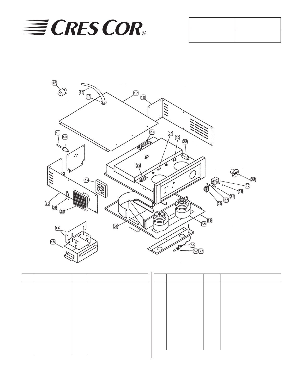
HOT UNIT REPLACEMENT PARTS
Manufactured from 3/00 to present)
Include all information on nameplate when ordering parts
42
43
40
17
18
21
22
31
30
28
37
20
39
38
19
44
45
36
35
323433
HOT UNIT REPLACEMENT PARTS (Manufactured from 3/00 to present)
Item DESCRIPTION REQ’D
17 Cover, Top 1 6169-161 6169-161
18 Cover, RH Side 1 6169-162 6169-162
19 Bottom Plate 1 0672-310 0672-310
20 Cover, LH Side 1 6169-163 6169-163
21 Term. Block, Rear 1 0852-090 0852-090
22 Terminal Block 1 0852-091 0852-091
23 Pilot Light, Yellow 1 0766-094 0766-095
24 Pilot Light, Yellow 1 0766-094 0766-095
25 Switch Kit 1 0808-118-K 0808-116
26 Plug Button 1 0847-004 0847-004
27 Thermostat 1 0848-062-K 0848-062-K
28 Thermometer 1 5238-034 5238-034
29 Transformer
110V/220V
30 Vent Fan Switch 1 0848-034 0848-034
31 Hi-Limit Switch 1 0848-033 0848-033
1 0769-159 0769-159
Part No’s. per Hot Unit
HU-18-671-44-G HU-18-671-45-G
Item DESCRIPTION REQ’D
32 Clamp, T-Stat Bulb 1 0567-496 0567-496
33 “ , Thermometer 1 0806-055 0806-055
34 Spacer 1 0818-017 0818-017
35 Blower Motor Kit 2 0769-005-K 0769-006-K1
36 Heater Kit 1 0811-022-K 0811-023-K
37 Vent Fan 1 0769-045-K 0769-029-K
38 Vent Fan Filter 1 0769-140 0769-140
39 Catch-Latch Ass’y. 2 1246-021 1246-021
40 Fuse Holder 1 0807-048 0807-048
41 Fuse 1 0807-058 0807-058
42 Power Supply Cord 1 0810-065 0810-039
43 Strain Relief Cord 1 0818-050 0818-050
44 Baffl es 1 1052-063 1052-063
45 Humidity Pan 1 1017-076 1017-076
46 Plug, Twist Lock, Alt. 1 0840-036 Not Available
28
27
26
24
23
25
Part No’s. per Hot Unit
HU-18-671-44-G HU-18-671-45-G
Call Toll-free: 877-CRES COR (273-7267) • Fax: 800-822-0393 • www.crescor.com
Page 13
Hot Cabinet
FL-1917-KFC-M
5925 Heisley Road • Mentor, OH 44060-1833
HOT UNIT REPLACEMENT PARTS
Manufactured from 10/97 thru 3/00)
Include all information on nameplate when ordering parts
Rev. 14 (10/08)
Page 13 of 16
HOT UNIT REPLACEMENT PARTS (Manufactured from 10/97 to 3/00)
Item DESCRIPTION REQ’D
17 Cover, Top 1 6169-161 6169-161
18 Cover, RH Side 1 6169-162 6169-162
19 Bottom Plate 1 0672-310 0672-247
20 Cover, LH Side 1 6169-163 6169-163
21 Term. Block, Rear 1 0852-090 0852-090
22 Terminal Block 1 0852-091 0852-091
23 Pilot Light, Yellow 1 0766-094 0766-095
24 Pilot Light, Yellow 1 0766-094 0766-095
25 Switch Kit 1 0808-118-K 0808-116
26 Plug Button 1 0847-004 0847-004
27 Thermostat 1 0848-062-K 0848-062-K
28 Thermometer 1 5238-034 5238-034
29 Transformer
110V/220V
30 Vent Fan Switch 1 0848-034 0848-034
31 Hi-Limit Switch 1 0848-033 0848-033
1 0769-159 0769-159
Call Toll-free: 877-CRES COR (273-7267) • Fax: 800-822-0393 • www.crescor.com
Part No’s. per Hot Unit
HU-18-671-44-G HU-18-671-45-G
Item DESCRIPTION REQ’D
32 Clamp, T-Stat Bulb 1 0567-496 0567-496
33 “ , Thermometer 1 0806-055 0806-055
34 Spacer 1 0818-017 0818-017
35 Blower Motor Kit 2 0769-005-K 0769-006-K1
36 Heater Kit 1 0811-022-K 0811-023-K
37 Vent Fan 1 0769-045-K 0769-029-K
38 Vent Fan Filter 1 0769-140 0769-140
39 Catch-Latch Ass’y. 2 1246-021 1246-021
40 Fuse Holder 1 0807-048 0807-048
41 Fuse 1 0807-058 0807-058
42 Power Supply Cord 1 0810-065 0810-039
43 Strain Relief Cord 1 0818-050 0818-050
44 Baffl es 1 1052-063 1052-063
45 Humidity Pan 1 1017-076 1017-076
46 Plug, Twist Lock, Alt. 1 0840-036 Not Available
** Note: When ordering replacement Hot Units, low-profi le water
pan 1017-076 is required.
Part No’s. per Hot Unit
HU-18-671-44-G HU-18-671-45-G
Page 14

Hot Cabinet
FL-1917-KFC-M
Rev. 14 (10/08)
Page 14 of 16
5925 Heisley Road • Mentor, OH 44060-1833
HOT UNIT REPLACEMENT PARTS
Manufactured thru 10/97)
Include all information on nameplate when ordering parts
HOT UNIT REPLACEMENT PARTS (Manufactured thru 10/97)
Item DESCRIPTION REQ’D
17 Cover, Top 1 6169-067 6169-067
18 Cover, RH Side 1 6169-083 6169-083
19 Bottom Plate 1 0672-162 0672-162
20 Cover, LH Side 1 6169-085 6169-084
21 Term. Block, Rear 1 0852-090 0852-090
22 Terminal Block 1 0852-091 0852-091
23 Pilot Light, Yellow 1 0766-048 0766-045
24 Pilot Light, Yellow 1 0766-047 0766-046
25 Switch Kit 1 0808-081 0808-080
26 Plug Button 1 0847-004 0847-004
27 Thermostat 1 0848-062-K 0848-062-K
28 Thermometer 1 5238-024 5238-024
29 Transformer
110V/220V
30 Vent Fan Switch 1 0848-034 0848-034
31 Hi-Limit Switch 1 0848-033 0848-033
1 0769-159 0769-159
Call Toll-free: 877-CRES COR (273-7267) • Fax: 800-822-0393 • www.crescor.com
Part No’s. per Hot Unit
HU-18-671-44-F HU-18-671-45-F
Item DESCRIPTION REQ’D
32 Clamp, T-Stat Bulb 1 0567-496 0567-496
33 “ , Thermometer 1 0806-055 0806-055
34 Spacer 1 0818-017 0818-017
35 Blower Motor Kit 2 0769-005-K 0769-006-K1
36 Heater Kit 1 0811-022-K 0811-023-K
37 Vent Fan 1 0769-045-K 0769-029-K
38 Vent Fan Filter 1 0769-140 0769-140
39 Catch-Latch Ass’y. 2 1246-021 1246-021
40 Fuse Holder 1 0807-048 0807-048
41 Fuse 1 0807-058 0807-058
42 Power Supply Cord 1 0810-065 0810-039
43 Strain Relief Cord 1 0818-050 0818-050
44 Baffl es 1 1052-063 1052-063
45 Humidity Pan 1 1017-0051 1017-051
46 Plug, Twist Lock, Alt. 1 0840-036 Not Available
Part No’s. per Hot Unit
HU-18-671-44-G HU-18-671-45-G
Page 15

Hot Cabinet
FL-1917-KFC-M
5925 Heisley Road • Mentor, OH 44060-1833
WIRING DIAGRAMS for 0671-044-G and 0671-045G
Rev. 14 (10/08)
Page 15 of 16
Call Toll-free: 877-CRES COR (273-7267) • Fax: 800-822-0393 • www.crescor.com
Page 16

Hot Cabinet
FL-1917-KFC-M
Rev. 14 (10/08)
2148 WAT TS, 120 VOLTS
1 PHASE, 60 HZ., 16.6 AMPS
Page 16 of 16
5925 Heisley Road • Mentor, OH 44060-1833
WIRING DIAGRAMS for 0671-044-F and 0671-045F
SW3
SW2
4
BM
10
BM
5
7
H1
CORD
G
W
5-20P
TB2
13
2
1
TB1
3
14
15
3
2
TEMP.
(12V)
(12V)
1
T
5
16
THIS LEAD MAY
BE OMITTED
TM
12
11
t
DISPLAY
10
4
8
7
18
17
10
VF
S1
TH1
F1
68
1
9
8
6
SW1
P1
HEATER ON
R
11
A
P2
POWER ON
LEGEND
FUSE
F1
MOTOR- BLOWER
BM
HEATER
H1
PILOT LIGHT, RED, HEATER ON
P1
PILOT LIGHT, AMBER, POWER ON
P2
SENSOR
S1
SWITCH,SPST
SW1
SWITCH, HIGH LIMIT
SW2
SWITCH, VENT FAN
SW3
TRANSFORMER
T
THERMOSTAT
TH1
TERMINAL BLOCK
TB1
TERMINAL BLOCK
TB2
THERMOMETER
TM
VENT FAN
VF
SLEEVING
0815-022-06
SLEEVING
2148 WAT TS, 240 VOLTS
1 PHASE, 60 HZ., 8.3 AMPS
t°
S1
CORD
6-15P
THIS LEAD MAY
BE OMITTED
TM
12
11
DISPLAY
10
TEMP.
P1
HEATER ON
7
SW2
9
TH1
4
R
8
H1
TB2
G
13
BM
F1
2
(12V)
(12V)
14
1 2
T
5
16
18 15
384
7
19
17
1
TB1
3
BM
10
12
10
VF
SW3
5
12
6
11
A
P2
POWER ON
8
6
12
SW1
2
1
Call Toll-free: 877-CRES COR (273-7267) • Fax: 800-822-0393 • www.crescor.com
 Loading...