

Page 1
DELHI INDUSTRIES INC.
DESCRIPTION
UNPACKING
GENERAL SAFETY INSTRUCTIONS
INSTALLATION
300 SERIES - ROOF EXHAUSTERS
OPERATION INSTRUCTIONS AND PARTS MANUAL
MODELS: 307, 309, 310, 312, 315, 318
instruction
Always disconnect power source before working on or near a motor or its connected load. Lock the power
Read installation and operation instructions carefully before attempting to install, operate or service DELHI 300 SERIES
BLOWERS. Failure to comply with instructions could result in personal injury and/or property damage. Retain
for future reference.
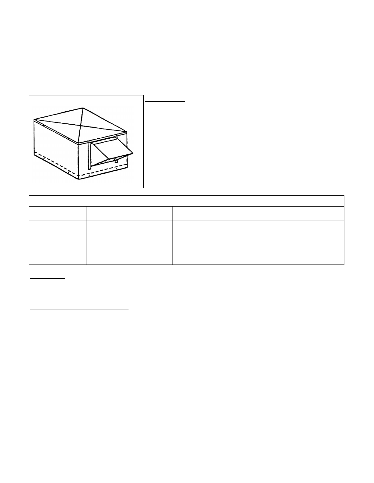
Figure 1: DELHI 300 SERIES
DELHI 300 Series Blowers are designed as a quiet and efficient outdoor roof
exhauster for high-rise apartments, schools, and commercial industrial
applications. These forward curved, double inlet blowers are enclosed in a
sturdy insulated steel cabinet c/w a recessed bottom for mounting to an
existing curb, with discharge in any of four positions. These blowers are belt
drive and may be installed with or without back draft dampers.
Motor, drive installations and servicing may be completed through a
removable top cover.
Prelubricated ball bearings, motor bracket, back draft dampers and
hardware, motor adjustment hardware and a dynamically balanced wheel are
standard equipment. Operating temperature range is -65 to 250 deg. F.
Maximum HP Ratings and Shaft Details
Model No. Max. H.P. Shaft Dia. Shaft End
307
309
310
312
315
318
3/4
3/4
1-1/2
2
3
3/4
3/4
3/4
3/4
1
1
keyway
keyway
keyway
keyway
keyway
keyway5
Once the packaging has been removed inspect the unit carefully. Check for loose, missing, or damaged parts. Rotate
the wheel by hand to ensure the wheel spins freely. Tighten all set screws.
1
disconnect in the open position and tag to prevent unauthorized application of power.
2
Follow all local and national electrical and safety codes.
3
Blower must be electrically grounded. This can be accomplished by using a separate ground wire connected
to the bare metal of blower frame, or other suitable means.
4
Ensure that the power source conforms to the requirements of your equipment.
5
Do not put hands near or allow loose and hanging clothing to be near belts, pulleys, or blower wheel while the
unit is running.
NOTE: Check the interior of the blower housing. It should be clean and free of debris.
1
Rotate the blower wheel by hand. It should not rub against the housing inlet. If rubbing occurs, loosen the set
screws on the wheel hub and shift the wheel to obtain clearance. Retighten all set screws.
DELHI INDUSTRIES INC., 523 JAMES ST., DELHI, ONTARIO, CANADA N4B 2Z3 PH:(519)582-2440 FX:(519)582-0581
OIPM-300-B
AUGUST 1998
Page 2
DELHI INDUSTRIES INC.
The
first
damper
tobeinstalled
should
overlap
the
WARNING:
EXCESSIVE
BELT
TENSION
IS
THE
MOST
FREQUENT
CAUSE
OF
BEARING
WEAR
AND
RESULTING
WARNING:
A
GROUND
WIRE
MUST
BE
CONNECTED
FROM
THE
MOTOR
HOUSING
TOASUITABLE
ELECTRICAL
Establish
the
direction
of
exhauster
discharge.
Carefully
lift
the
unit
and
position
over
the
existing
curb.
Confirm
the
unit
is
within the bracket.
Adjust
belt
tension
by
turning
the
motor
adjustment
hook
bolt.
Ideal
belt
tension
is
the
lowest
tension
at
which
the
belt
will
not
2
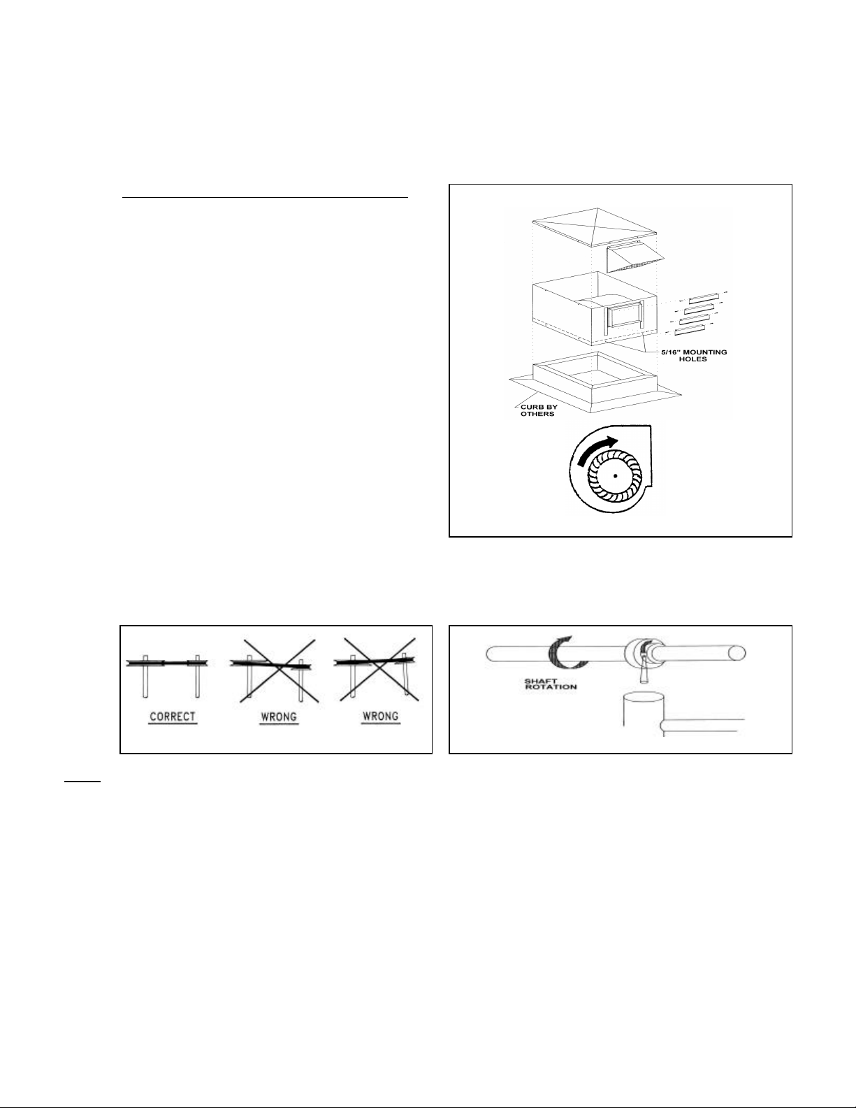
properly seated and secure into position by fastening through the 5/16" holes located in the unit's skirt.
OPTIONAL: INSTALLING BACK DRAFT DAMPERS: Figure 2: Installation Method
3
discharge baffle with subsequent dampers overlapping the
previous damper, until the top of the discharge is reached.
Use the #8 x 1-1/4" screws provided to secure the damper
into position with the brake facing inward. Insert the
screws through the plastic snap bushing located on either
side of the blower discharge into the shutter recess.
Maintain that each damper installed rotates freely within
the snap bushing. (See Figure 2)
4
Insert the exhaust cowl (air direction downward) into the
channels provided on either side of the exhaust port.
5
Mount the blower sheave on the blower shaft and tighten
its set screw securely on the key of the shaft. (See Table
1 for Drive Data)
6
Mount the motor sheave on the motor shaft. Leave some
clearance between the pulley and the motor end bell.
Tighten the set screws on the key of the motor shaft.
7
Slide the square head bolts into the channel provided in
the motor bracket. Place the motor into position, finger
tighten the nuts to temporarily secure the motor. Attach
the motor adjustment (belt tension) assembly.
WHEEL ROTATION
8
With the motor adjusting bolt in its minimum position install the V belt within the sheave grooves. Slide the motor within the
motor bracket to ensure proper pulley alignment (see Figure 3). A straight edge across the face of the driven pulley should be
parallel to the belt once proper alignment has been achieved. Tighten the nuts on the motor base to anchor the motor position
Figure 3: Pulley Alignment Figure 4: Bearing Replacement
NOTE: Pulley alignment may change when adjusting variable pitch pulleys.
9
slip during start up. A rule of thumb suggests that 3/4" of deflection mid span under medium finger pressure (2-3 lbs.) for every
foot of span is approximately proper belt tension. Lock the motor adjustment (belt tension) assembly once proper belt tension
has been achieved.
NOISE
10
Before connecting the motor to the electrical supply, check the electrical characteristics and wiring instructions as indicated on
the motor nameplate to ensure proper voltage and phase. Make your electrical connections.
GROUND
OIPM-300-B AUGUST 1998
Page 3

DELHI INDUSTRIES INC.
307
309
310
312
315
318
Pulley
Pulley
Range
48 FRAME
48 FRAME
FRAME
FRAME
FRAME
FRAME
OPERATION
MAINTENANCE
WARNING: DISCONNECT POWER SUPPLY BEFORE SERVICING THE BLOWER
Table 1: Drive Table
Motor Blower RPM 56/143T/145T 56/143T/145T 56/143T/145T 182T/184T
3-1/4" 10 401 - 548 - - - - - - - - - 4L51 4L55 - - -
3/4 HP 8 505 - 690 4L37 4L41 4L44 4L48 - - - - - -
MAX. 7 580 - 792 4L36 4L40 4L42 4L46 - - - - - -
IVL34 BK110H 422 - 464 - - - - - - - - - - - - 4L55 B59
IVP44 BK90H 717 - 802 4L39 4L43 4L45 B48 B51 B57
NOTE TO CONVERT:
A) 48 FRAME TO 56/143T/145T FRAME ADD 1" TO BELT LENGTH
B) 56/143T/145T FRAME TO 182T/184T FRAME ADD 2" TO BELT LENGTH
C) 4L TO B BELTS SUBTRACT 3" FROM THE BELT LENGTH (eg.: 4L48 EQUIVALENT TO A B45 - RPM WILL VARY SLIGHTLY)
12 333 - 455 - - - - - - - - - - - - 4L58 - - -
9 447 - 611 - - - - - - - - - 4L49 - - - - - -
6 680 - 929 4L34 4L38 4L40 - - - - - - - - -
5 824 - 1125 4L33 4L36 - - - - - - - - - - - BK160H 252 - 309 - - - - - - - - - - - - - - - - - BK140H 310 - 356 - - - - - - - - - - - - - - - - - BK130H 357 - 386 - - - - - - - - - - - - 4L58 4L64
BK120H 387 - 421 - - - - - - - - - - - - 4L57 B61
BK100H 465 - 515 - - - - - - - - - 4L49 4L53 B58
BK90H 516 - 579 4L38 4L41 4L44 4L48 B50 B56
BK80H 580 - 663 4L36 4L40 4L42 4L46 B49 B54
BK70H 664 - 773 4L34 4L38 4L41 4L45 B47 B53
BK60H 774 - 963 4L33 4L37 4L39 B41 B45 B51
BK50H 964 - 1203 4L31 4L35 B36 B40 - - - - - -
BK40H 1204 - 1504 4L30 4L34 B34 - - - - - - - - BK130H 491 - 543 - - - 4L49 4L52 4L56 B58 B64
BK120H 544 - 592 4L44 4L48 4L50 4L54 B56 B62
BK110H 593 - 648 4L42 4L46 4L49 4L52 B55 B61
BK100H 649 - 716 4L41 4L44 4L47 4L51 B53 B59
BK80H 803 - 911 4L37 4L41 4L44 B46 B50 B56
BK70H 912 - 1053 4L36 4L39 B40 B44 B48 - - -
BK60H 1054 - 1281 4L34 4L38 B39 - - - - - - - - -
BK50H 1282 - 1567 4L32 4L36 B37 - - - - - - - - -
BK40H 1568 - 1960 4L31 4L35 - - - - - - - - - - - -
1
After electrical connections are completed, energize the unit momentarily and ensure that the rotation of the wheel is correct (see Figure 2). Apply full
power.
2
With the air system in full operation, all ducts attached and top cover in place, measure current input to the motor and ensure that it is less than the
rated full load motor amperage.
3
Proper adjustment to the belt tension is critical for quiet efficient operation.
4
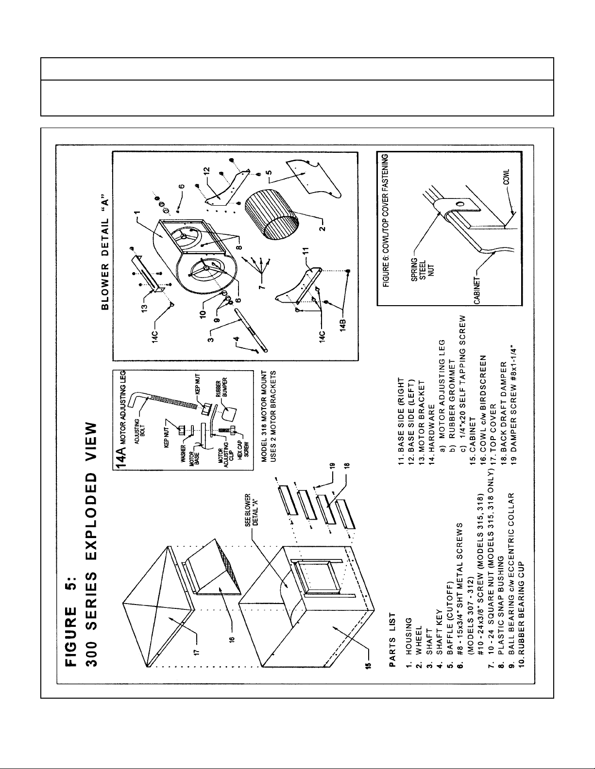
Replace the top cover for proper operation of this unit. NOTE: When replacing the top cover ensure that the spring steel nut is positioned over the top
flange of the cowl such that when the top cover has been replaced, the two fasteners secure the cowl and top cover to the cabinet (See Figure 6).
1
Inspect and tighten all bearing collar and wheel set screws after the first 50 to 100 hours of operation and periodically thereafter.
2
Follow motor manufacturer's instructions for motor lubrication. Remove any excess lubrication.
3
Check the drives.
a. Tighten set screws on sheaves, wheel and bearing locking collars.
b. Check belt tension and alignment.
c. Replace cracked or worn belts.
4
Check wiring to be sure it is secure and well insulated.
5
Blower bearings are permanently lubricated and require no further lubrication.
6
Inspect V-belts for wear and proper tension. If it is necessary to replace one belt on a multiple belt drive, replace all the belts with a matched set. Do
not use belt dressing.
7
Clean the blower wheel periodically. Material build up on the blades can cause wheel imbalance which may result in wheel or bearing failure.
8
To reinstall replacement ball bearings press the locking collar against the inner ring of the bearing and turn in the direction of the shaft rotation until
engaged. Insert a drift pin into the pin hole and tap lightly to set. Tighten set screw on locking collar firmly (see Figure 4).
9
Should further service to the blower be necessary, refer to the exploded view illustration. (See Figure 5).
OIPM-300-B
AUGUST 1998
Page 4
DELHI INDUSTRIES INC.
DELHI INDUSTRIES INC. WARRANTY
Delhi Air Moving Products are guaranteed for a period of one year against manufacturing defects in material and
workmanship when operating under normal conditions. Liability is limited to the replacement of defective parts. Labour
and transportation costs are not included.
OIPM-300-B
AUGUST 1998
 Loading...