

Cres Cor 275-38-1810-KDT Installation Manual
KD Rack
Assembly
FL-2350
5925 Heisley Road • Mentor, OH 44060-1833
ASSEMBLY INSTRUCTIONS
for KNOCK DOWN RACKS
275-70-1824-KD, 275-70-1820-KD and 275-38-1810-KDT
TOOLS NEEDED:
7/16” & 9/16” Socket Head Wrench
RACK PARTS SUPPLIED for
275-70-1824-KD, 275-70-1820-KD
QTY DESCRIPTION
2 Side assemblies, welded with angles
6 Support braces, with tapped holes
4 Casters, 5” dia. swivel
8 Clips, washer
12 Screws, hex head machine 5/16-18
Rev. 3 (5/12) Page 1 of 2
RACK PARTS SUPPLIED for
275-38-1810-KDT
QTY DESCRIPTION
2 Side assemblies, welded with angles
4 Support braces, with tapped holes
4 Casters, 5” dia. swivel
4 Clips, washer
8 Screws, hex head machine 5/16-18
1 Top shelf
REPLACEMENT PARTS:
DESCRIPTION PART NO.
Loose Hardware Kit .................................. 6274-021
Top Shelf Kit ............................................. 1269-052
Brace Support Kit .....................................0520-051
Caster Kit (Plate) .......................................0569-327-K
Caster Kit (Stem) ......................................0569-328-K
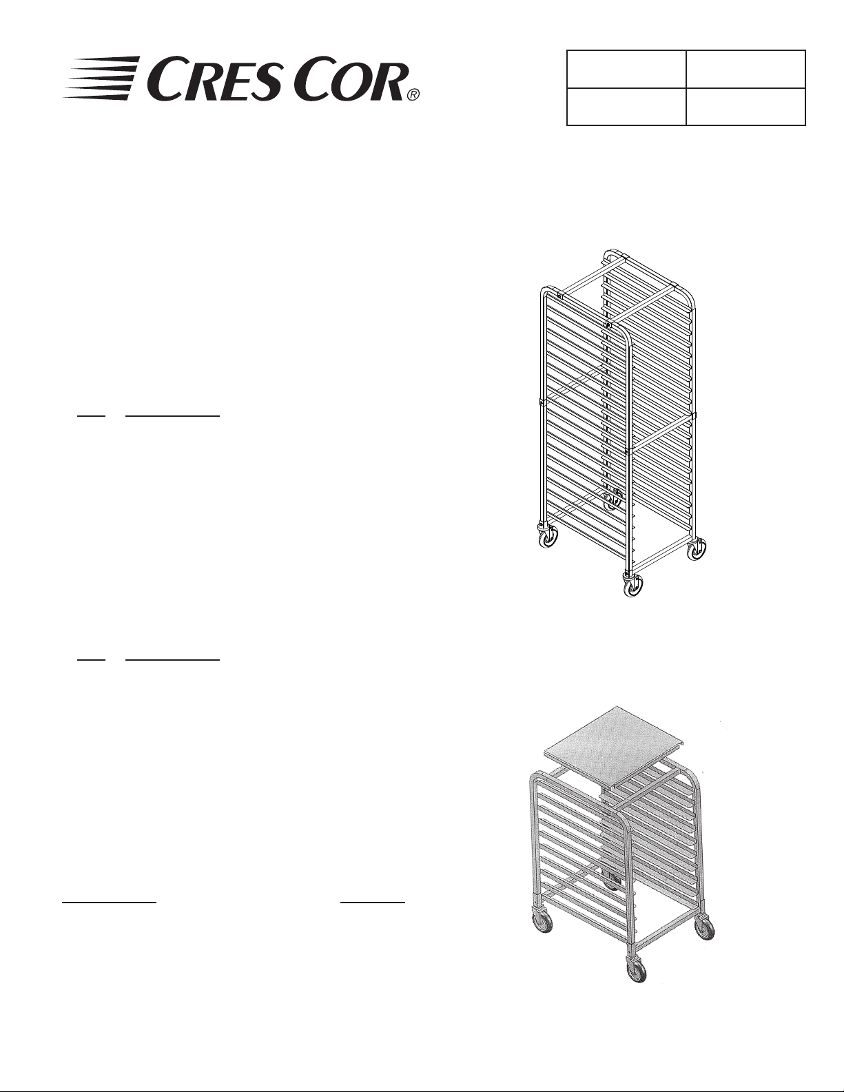
Figure 1
275-70-1820-KD
Figure 2
275-38-1810-KDT
Call Toll-free: 877-CRES COR (273-7267) • Fax: 800-822-0393 • www.crescor.com
KD Rack
Assembly
FL-2350
5925 Heisley Road • Mentor, OH 44060-1833
ASSEMBLY INSTRUCTIONS
for KNOCK DOWN RACKS
275-70-1824-KD, 275-70-1820-KD and 275-38-1810-KDT
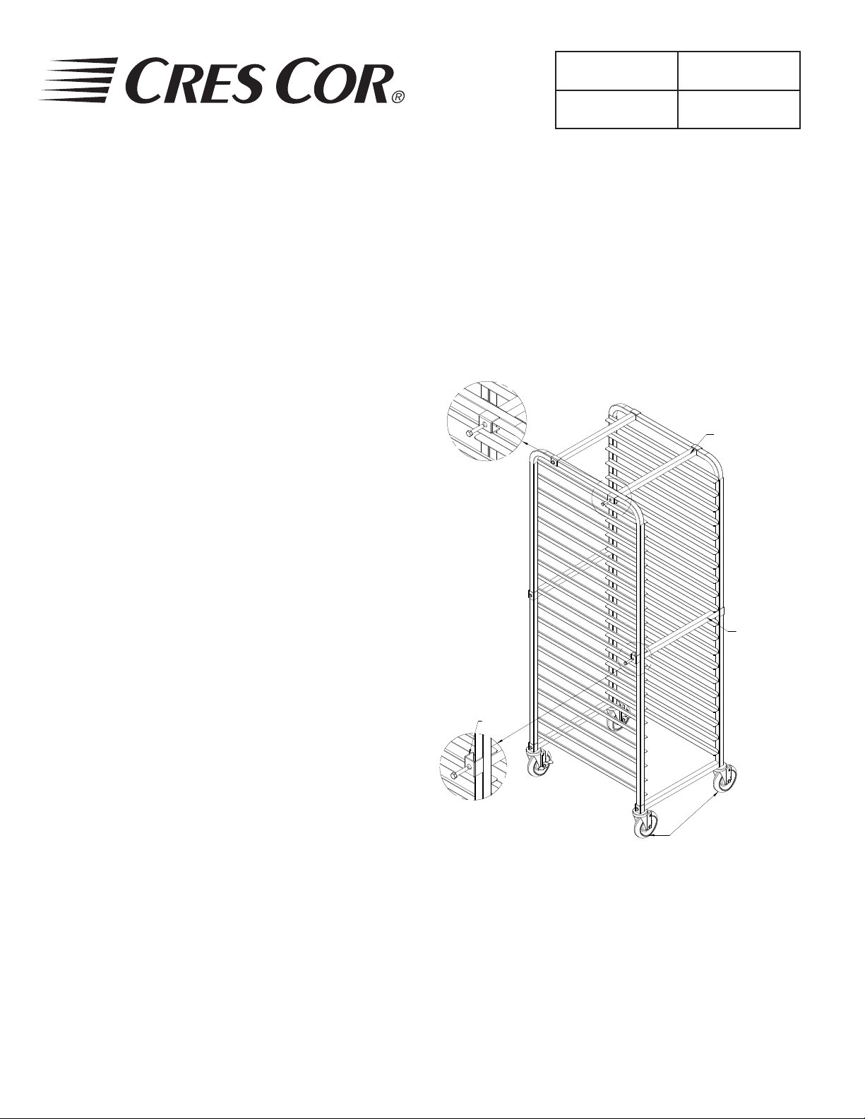
HOW TO ASSEMBLE FULL-SIZE RACKS 275-70 SERIES:
1. Attach (4) support braces to the angle side of one of the side
assemblies; (2) at the top and (2) at the center holes on the side
tubing with the clips and screws provided (See Fig. 3).
a. Slide the clip around the outside of the tubing lining up the
hole with the hole in the tubing post.
b. Insert the screw through the clip into the support brace.
2. Place the second side assembly (with angles facing each other)
against the support braces; lining up the holes.
3. Add (4) more clips and fasten together with the screws.
4. Turn the rack so the front opening of the rack is facing you.
5. Insert the (2) casters with brakes into each bottom of the side
tubing on that same opening of the rack.
(For model 275-70-1824-KD only).
6. Insert a support brace in between the side tubings and fasten them
to the brace with screws.
7. Lift and turn the rack to insert the other (2) casters on the other
side and fasten them to the side tubing and support braces with
the screws.
8. Stand the rack upright and make sure all screws are tight.
DETAIL B
Rev. 3 (5/12) Page 2 of 2
SUPPORT BRACES
(TOP)
SUPPORT BRACES
(CENTER)
HOW TO ASSEMBLE HALF-SIZE RACK 275-38 SERIES:
1. Place one side assembly on the oor with angles facing up and
insert (2) casters into the bottom of the side tubing.
2. Repeat with the second side assembly.
3. Attach the (2) support braces to the angle side of one of the
assemblies by lining them up with the caster hole on the side
tubing with the hole in the support brace. Fasten together with
screws.
4. Place the second side assembly (with angles facing each other)
against the support braces; lining up the holes at the bottom.
Fasten with screws.
5. Insert the (2) support braces under the top shelf between the
side assemblies; lining up the holes. Add (4) clips and fasten with
screws
6. Place the top shelf over the side and top tubing and push shelf
down to t.
7. Make sure all screws are tight.
Call Toll-free: 877-CRES COR (273-7267) • Fax: 800-822-0393 • www.crescor.com
CLIPS
DETAIL A
Figure 3
275-70-1820-KD
NOTE THAT THE SAME CASTERS ARE
MOUNTED ON THE SAME SIDE OF THE
RACK OPENING. CASTERS WITH BRAKES
ARE ON MODEL 275-70-1824KD ONLY
 Loading...