

Page 1
Proofi ng
Cabinet
FL-0300-3
5925 Heisley Road • Mentor, OH 44060-1833
OPERATING and MAINTENANCE INSTRUCTIONS
Model: 120B and 121B Series Proofi ng Cabinets
ELECTRICAL SPECIFICATIONS:
Model No. Volts Watts Amps Hertz Phase NEMA
Machine
Screw
120-1816B
-1836B
121-1816B 120 1000 8.3 60 1 5-15
120-1816B 240
-1836B 240
121-1816B 240 240 900 3.8 60 1 6-15
All are designed for AC service.
120 1000 8.3 60 1 5-15
240 900 3.8 60 1 6-15
Rev. 7 (3/10) Page 1 of 4
4
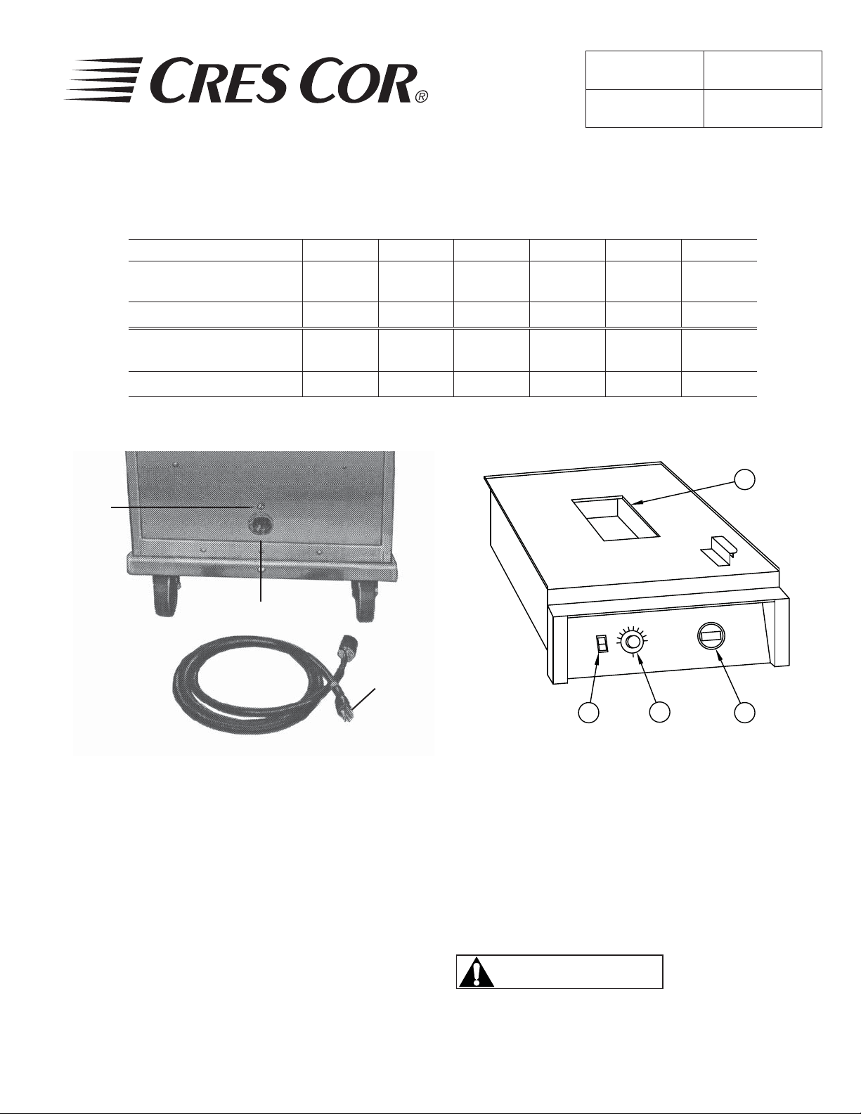
Twist clockwise and
lock for connection
FIGURE 1 FIGURE 2
HOW TO INSTALL CABINET:
Place cabinet near warm ovens. Do 1. NOT put in
drafty areas or near ventilating systems.
Plug cord into receptacle in back of unit.2.
Turn plug clockwise to lock. 3.
Plug other end into proper wall outlet.4.
Fill water pan (following steps a-c).5.
a. Lift off cover.
b. Fill with 3.5 qts. (3.3 liters) water.
Replace cover.
c. Adjust vents on cover to half open.
Standard
3-prong plug
1
2
PARTS IDENTIFICATION
1. Power Switch
2. Thermostat (Reservoir)
3. T emperature Display
4. Water Pan
Use of treated or
CAUTION
soft water may be
required for proper
operation and to maintain warranty.
3
Call Toll-free: 877-CRES COR (273-7267) • Fax: 800-822-0393 • www.crescor.com
Page 2
Proofi ng
Cabinet
FL-0300-3
Rev. 7 (3/10) Page 2 of 4
OPERATING and MAINTENANCE INSTRUCTIONS
Model: 120 and 121 Series Proofi ng Cabinets
HOW TO START UNIT:
Turn the POWER switch on. The 1. Yellow light will
come on.
Turn thermostat to #10.2.
Preheat cabinet for 30 minutes.3.
Put fresh or fully thawed dough into cabinet.4.
NOTE: The cabinet temperature will drop temperature
inside cabinet if cold dough is added.
Do NOT put frozen dough into cabinet
Turn thermostat to #9 and close door.5.
NOTE: No. 9 setting will give you a temperature of
95°F, and 90-95% humidity. Experiment with
different settings to get the exact temperature
and humidity you need. The thermometer shows
the temperature inside.
NOTE: Check water level in water pan if you are
proofi ng longer than 90 minutes. Fill with hot
water.
HOW TO TURN UNIT OFF:
Turn thermostat off. The red light will go out.1.
Turn the POWER switch off. The 2. Yellow light will
go out.
5925 Heisley Road • Mentor, OH 44060-1833
MAINTENANCE
HOT UNIT REMOVAL INSTRUCTIONS:
Unplug cord set from wall outlet and from back of 1.
cabinet.
Remove one screw from back of cabinet that is 2.
above receptacle.
Slide the whole unit out the front of the cabinet.3.
HOW TO CLEAN THE CABINET:
BEFORE cleaning
WARNING
the cabinet:
Allow cabinet to cool.1.
Remove Hot unit from cabinet.2.
Do NOT use abrasives or harsh 3.
chemicals.
Cleaning hints:
Wipe up spills as soon as possible.1.
Clean cabinet regularly to avoid heavy dirt build-up.2.
Make a test spot with cleaner.3.
Follow manufacturer’s directions on cleaner.4.
Do not mix cleaners.5.
Avoid drips and splashes.6.
HOW TO CLEAN THE UNIT:
Soil Cleaner Method
DOOR
(Polycarbonate)
CABINET
(Aluminum)
Inside
and
Outside
DIRT Mild *detergent and water.
GREASE and OIL Weak, alcohol-type cleaner.
DIRT Mild *detergent and hot
FINGERPRINTS,
GREASE and OIL
WATER SPOTS Mild abrasive cleaner 1. Apply with damp cloth.
*Mild detergents include soaps and non-abrasive cleaners.
Call Toll-free: 877-CRES COR (273-7267) • Fax: 800-822-0393 • www.crescor.com
water, or mild abrasive
cleaner.
Steam (no strong alkaline
additive)
Chemical oven cleaner for
aluminum
Mild abrasive cleaner; oily
or waxy cleaner.
1. Wipe with soft, damp cloth.
2. Rinse well.
1. Wipe with soft, damp cloth.
2. Rinse well.
1. Use soft, damp cloth.
2. Rinse with hot water.
3. Wipe dry
1. Rinse after steam cleaning.
2. Wipe dry.
Follow oven cleaner manufacturer’s
directions.
Apply with soft, clean cloth.
2. Rinse and dry.
Page 3

Proofi ng
Cabinet
FL-0300-3
5925 Heisley Road • Mentor, OH 44060-1833
Rev. 7 (3/10) Page 3 of 4
OPERATING and MAINTENANCE INSTRUCTIONS
Model: 120B and 121B Series Proofi ng Cabinets
DELIME OR DESCALE RESERVOIR PARTS AS REQUIRED
CAUTION
W ARRANTY COVERAGE MAY BE AFFECTED WITHOUT PROPER CLEANING.
TROUBLE-SHOOTING CHART:
FAILURE POSSIBLE CAUSE
1. Yellow light at switch does not light.
2. Unit does not get hot.
3. Unit will not turn off. 3a. Defective electrical parts.
4. Humidity is low 4a. Water in pan may be low
If cause is none of the above, refer to our list of Authorized Service Centers, FL-1400.
Instructions for replacing parts are included in replacement parts kits.
TO PREVENT DAMAGING BUILD-UP.
1a. Circuit breaker/fuse to wall outlet is blown.
1b. Cord is unplugged from wall outlet or cabinet.
1c. Switch is “OFF”.
2a. Thermostat set too low or is “OFF”.
2b. Water in pan may be low.
2c. Switch is “OFF”.
UNPLUG UNIT FROM WALL OUTLET.
4b. Thermostat set too low
REPLACEMENT PARTS:
DESCRIPTION 120 VOLT 240 VOLT
Proof Unit .............................................PU-18-747-42 ............PU-18-747-43
Water Pan ..............................................1019-002 ....................1019-002
Water Pan Cover ...................................1245-001 ....................1245-001
Heater Kit .............................................0811-005-K ................0811-015-K
Water Pan with Heater Kit ....................0756-014 ....................0756-015
Thermostat Kit ......................................0848-062-K ................0848-062-K
Thermometer Kit (Analog) ...................5238-030-K ................5238-030-K
Thermometer Kit (Digital °F) ...............5238-034-K ................5238-034-K
Thermometer °F only .......................5238-034 ....................5238-034
Transformer, 110/220V only ............0759-159 ....................0759-159
Thermometer Kit (Digital °C) ..............5238-034-K1 ..............5238-034-K1
Thermometer °C only .......................5238-034-1 .................5238-034-1
Transformer, 110/220V only ...........0759-159 ....................0759-159
Receptacle .............................................0713-011 ....................0713-012
Switch ...................................................0808-116 ....................0808-1 16
Cord Set Assembly ...............................0810-031-01 ...............0810-032-01
Cord Holder ..........................................5258-010 ....................5258-010
Pilot Light .............................................0766-094 ....................0766-095
Call Toll-free: 877-CRES COR (273-7267) • Fax: 800-822-0393 • www.crescor.com
Page 4

Proofi ng
Cabinet
FL-0300-3
Rev. 7 (3/10) Page 4 of 4
OPERATING and MAINTENANCE INSTRUCTIONS
Model: 120 and 121 Series Proofi ng Cabinets
52
FOR 220V
TRANSFORMER
110V/220V
50
384
2 1
51
5
50
51
FOR 120V
TRANSFORMER
110V/220V
5925 Heisley Road • Mentor, OH 44060-1833
THERMOSTAT
35
HEATER
4
50
4
3 21
8
51
5
51
A
50
34
SENSOR
t°
DIP SWITCH (SW1)
SETTINGS
21 3 1 23
OFF
F°
LEGEND
A – Amber “Power Light”
OFF
C°
t°
SENSOR
OPTIONAL
L6-15P PLUG
240V, 15A
YX
GG
ELECTRICAL SPECS.
Model 0747-042 Series
1000W, 120V, 60 Hz, 1Ph
Model 0747-043 Series
900W, 240V, 60 Hz, 1Ph
21
BW
L5-20P PLUG
120V, 20A
Call Toll-free: 877-CRES COR (273-7267) • Fax: 800-822-0393 • www.crescor.com
 Loading...