


5925 Heisley Road • Mentor, OH 44060-1833
INSTALLATION, OPERATION and MAINTENANCE
MANUAL for Cres Cor
RADIANT OVENS
Ovens
Rev. 6 (2/09) Page 1 of 12
FL-2340
1000-CH-SS
1000-CH-AL
Models: 1000-CH SERIES
Cabinet model number:
Cabinet serial number:
Authorized Service Agency:
Ph: Fax:
Keep this manual for future reference.
Call Toll-free: 877-CRES COR (273-7267) • Fax: 800-822-0393 • www.crescor.com
1000-CH-SS-SPLIT
1000-CH-AL-SPLIT
Ovens
Rev. 6 (2/09) Page 2 of 12
FL-2340
5925 Heisley Road • Mentor, OH 44060-1833
TABLE OF CONTENTS
SUBJECT PAGE
INSTALLATION INSTRUCTIONS ......................................................................................3, 4
OPERATING INSTRUCTIONS ............................................................................................5
Illustration, Control Panel ............................................................................................ 5
MAINTENANCE INSTRUCTIONS
How to Clean the Unit ..................................................................................................6
Trouble Shooting Guide ...............................................................................................7
Replacement Parts ........................................................................................................8
Illustration; Ovens ........................................................................................................9
Wiring Diagram for 1000-CH-SS or 1000-CH-AL ...................................................... 10,11
Wiring Diagram for 1000-CH-SPLIT ..........................................................................12
SERVICE POLICY and AGENCY LIST .........................................................................FL-1400
WARNING
RISK OF FIRE OR ELECTRIC SHOCK
DO NOT OPEN
WARNING: TO REDUCE THE RISK OF FIRE OR ELECTRIC SHOCK,
DO NOT REMOVE COVER (OR BACK)
NO USER-SERVICEABLE PARTS INSIDE
REPAIR SHOULD BE DONE BY AUTHORIZED SERVICE
PERSONNEL ONLY
Call Toll-free: 877-CRES COR (273-7267) • Fax: 800-822-0393 • www.crescor.com

Ovens
FL-2340
Rev. 6 (2/09) Page 3 of 12
5925 Heisley Road • Mentor, OH 44060-1833
INSTALLATION INSTRUCTIONS
VENTING YOUR OVEN:
The purpose of ventilating hoods is to direct and 1.
capture smoke, grease-laden vapors, heat, odors, or
fumes.
Low temperature equipment (maximum 2.
temperature 250°F/121°C) does not produce heat,
odors, fumes, grease-laden vapors or smoke and is
not required to be vented.
SPECIFICATIONS: All units are rated 3000 watts.
CMP MODEL NOS.
SINGLE OVENS Volts Ph Hz. Amps Volts Amps Ph Wire Volts NEMA
1000CHSSSPLIT
OR
1000CHALSPLIT
ELECTRICAL SPECS
(AC SERVICE)
208
240
1
1
60
60
ELEC. LOAD POWER SUPPLY REQUIREMENT
14
13
Most jurisdictions consider our low-temperature 3.
ovens (maximum temperature is 350°F/177°C) as
low-heat appliances not requiring vent hoods.
Installation must conform with local codes. The 4.
authority having jurisdiction of enforcement of
the codes will have the responsibility for making
interpretations of the rules.
208
240
20
20
1
1
2
2
208
240
6-20P
6-20P
1000CHSSSPLIT3
OR
1000CHALSPLIT3
208
240
3
3
60
60
8
7
208
240
20
20
3
3
3
3
208
240
L15-20P
L15-20P
SPECIFICATIONS: All units are rated 6000 watts. *For USA Only - Canadian is 6-50P
CMP MODEL NOS.
DOUBLE OVENS Volts Ph Hz. Amps Volts Amps Ph Wire Volts NEMA
1000CHSS
OR
1000CHAL
1000CHSS3
OR
1000CHAL3
Model number “AL” is aluminum outer body with stainless steel doors and interior.
All models designed for AC Service. Model number may have the letters: M, 2M, HT, Z, S or CAN.
ELECTRICAL SPECS
(AC SERVICE)
208
240
208
240
1
1
3
3
60
60
60
60
ELEC. LOAD POWER SUPPLY REQUIREMENT
29
25
16
14
208
240
208
240
30
30
20
20
1
1
3
3
2
2
3
3
208
240
208
240
*6-30P
*6-30P
L15-20P
L15-20P
IDENTIFYING YOUR CABINET:
Look for this label on the back of your cabinet. This information is needed when calling for questions or service.
R
5925 HEISLEY RD. MENTOR, OHIO 44060
MOD.
MOD.
1000CH
FAA-K5645C-001
FAA-K5645C-001
SER.
SER.
29
AMPS
AMPS
VOLTS
VOLTS
208/240
3000
WATTS
WATTS
COMMERCIAL COOKING APPLIANCE
MADE IN USA
CSA certified to UL 197 Rev. 9
SAMPLE
Hz.
Hz.
60
60
PH.
PH.
1
1
UPPER RIGHT CABINET CORNER
R
C
US
R
Call Toll-free: 877-CRES COR (273-7267) • Fax: 800-822-0393 • www.crescor.com

Ovens
Rev. 6 (2/09) Page 4 of 12
FL-2340
INSTALLATION INSTRUCTIONS (continued)
HOW TO INSTALL CABINETS:
Remove all packing material from the inside and all 1.
vinyl from the outside of oven.
Place the oven in a well ventilated area on level fl oor. 2.
Clearance requirements: 3” (76mm) at the back, 2”
(51mm) at the top, 1” (25mm) at both sides.
Install the pan slide racks on the sidewalls, if necessary.3.
Slide drip pan(s) onto the bottom of the compartment(s).4.
Remove (3) screws at the bottom front of the oven, 5.
under the door (See Figure).
Screw the drip tray bracket to the oven in those holes 6.
and place the drip tray onto the bracket.
5925 Heisley Road • Mentor, OH 44060-1833
DRIP TRAY
All models are rated at 208/240 Volts.
NOTE: OVENS NEED TO BE INSTALLED BY A
QUALIFIED PERSON.
Check the voltage selector switch which is under an access
cover on the back of the oven near the power cord.
Flip the switch “UP” for 208 Volts
Flip the switch “DOWN” for 240 Volts
MAKE SURE THE SWITCH POSITION MATCHES
YOUR POWER SOURCE.
Order Cres Cor Kit #6126 060 to convert 1 Phase
ovens to 3 Phase
DRIP TRAY
BRACKET
SCREWS
HOW TO REVERSE THE DOOR OPENINGS, IF
NEEDED:
Unscrew and remove the latch from the door and 1.
magnetic strike from the cabinet.
Unscrew the hinges from the cabinet body and remove 2.
door.
Remove the screws plugging the mating hinge, latch 3.
and strike holes on the opposite sides of the cabinet
body and door.
Re-mount the hinges to the opposite side of the cabinet 4.
and door.
Remount the latch and strike to the opposite side5.
Call Toll-free: 877-CRES COR (273-7267) • Fax: 800-822-0393 • www.crescor.com

5925 Heisley Road • Mentor, OH 44060-1833
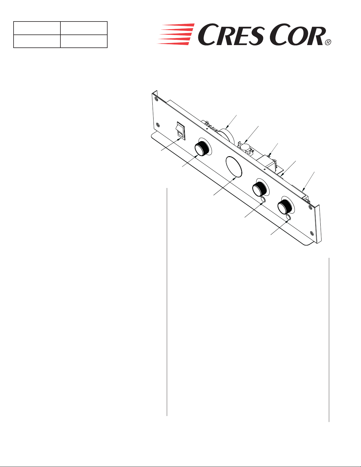
OPERATING INSTRUCTIONS
Power
Switch
Timer
Thermometer
Thermostat
“Hold”
Ovens
Rev. 6 (2/09) Page 5 of 12
Thermostat
“Cook”
FL-2340
FOR FIRST-TIME OPERATION ONLY:
A new oven needs to “burn off” factory oils and glue before
it’s fi rst use. Do NOT load food into oven until this has
been done!
Push switch to “ON”.1.
Set the 2. Cook thermostat to 325°F/163°C.
Set the 3. Hold thermostat to 150°F/66°C.
Set the timer to one (1) hour.4.
Allow oven to run automatically for one (1) hour of 5.
Cook cycle and 30 minutes of Hold cycle.
Turn oven off and let cool.6.
Wipe inside clean with detergent and hot water.7.
DOOR VENT ADJUSTMENT:
Open the door(s) and move the vent tabs on the
inner door(s) as needed to release humidity.
Yellow
Light
Green
Light
HOW TO START UNIT
(after fi rst-time operation):
Push POWER switch “ON”.
NOTE: For HOLD or COOK mode, preheat unit to desired
temperature for 30 minutes.
For Automatic Operation:
Set 1. Cook thermostat to the cooking temperature you
need.
Set 2. Hold thermostat to the warming temperature you
need. Proper food holding temperature is 140°F/60°C or
higher.
Set 3. Timer for the roasting time. The unit will
automatically switch to the pre-set “hold” temperature
after roasting time has expired.
For Holding Operation ONLY:
Cold food is NOT to be added when unit is
operating in HOLD mode.
Set 1. HOLD thermostat to the temperature you need.
Set Timer at zero.2.
WARNING
Air is VERY HOT when door is opened.
Call Toll-free: 877-CRES COR (273-7267) • Fax: 800-822-0393 • www.crescor.com
TO SHUT DOWN UNIT:
Push SWITCH to “OFF”.
NOTE: Ventilating fans will continue to run until cabinet is
cool. Do NOT disconnect the power supply to the
cabinet while the ventilating fan is still operating.

Ovens
Rev. 6 (2/09) Page 6 of 12
FL-2340
WARNING
5925 Heisley Road • Mentor, OH 44060-1833
HOW TO CLEAN THE UNIT:
BEFORE cleaning the cabinet:
1. Unplug cord from wall. Allow cabinet to cool.
2. Do NOT hose cabinet with water.
3. Do NOT get water on controls.
4. Do NOT use abrasives or harsh chemicals.
Wipe up spills as soon as possible.
Clean regularly to avoid heavy dirt build-up.
MODELS: 1000-CH-SS & 1000-CH-SS-SPLIT
SOIL CLEANER METHOD
Soap or mild detergent* and
water.
Mild abrasive made for
Stainless Steel.
Chemical oven cleaner made
for Stainless Steel.
STAINLESS
STEEL
CABINET
Inside and
Outside
Routine Cleaning
Stubborn Spots, Stains
Burnt on Foods or Grease
Hard Water Spots & Scale Vinegar
Cleaning Hints:
Use the mildest cleaning procedure that will do the job. 1.
Always rub in the direction of polish lines to avoid 2.
scratching the surface.
Use only a soft cloth, sponge, fi brous brushes, plastic or 3.
stainless steel pads for cleaning and scouring.
Rinse thoroughly with fresh water after every cleaning 4.
operation.
Always wipe dry to avoid water marks. 5.
1. Sponge on with cloth
2. Rinse
1. Apply with damp sponge or cloth.
2. Rub lightly.
Follow oven cleaner manufacturer’s
directions.
1. Swab or wipe with cloth.
2. Rinse and dry.
MODEL: 1000-CH-AL & 1000-CH-AL-SPLIT (Aluminum cabinet outside only with stainless steel doors and pan slides)
SOIL CLEANER METHOD
1. Use soft, damp cloth.
2. Rinse with hot water.
3. Wipe dry.
1. Rinse after steam cleaning.
2. Wipe dry.
1. Wipe with soft, damp cloth.
2. Rinse with hot water.
3. Wipe dry.
Follow oven cleaner manufacturer’s
directions
Apply with soft, clean cloth.
ALUMINUM
CABINET
Outer body
ONLY
Mild detergent* and hot water,
or mild abrasive cleaner.
Dirt
Steam (no strong alkaline
additive).
Detergent* and hot water.
Fingerprints, Grease, Oil
Water Spots Mild abrasive cleaner. Wipe with damp cloth.
Chemical oven cleaner made
for aluminum.
Mild abrasive cleaner.
Oily or waxy cleaner.
*Mild detergents include soaps and non-abrasive cleaners.
Call Toll-free: 877-CRES COR (273-7267) • Fax: 800-822-0393 • www.crescor.com

5925 Heisley Road • Mentor, OH 44060-1833
MAINTENANCE INSTRUCTIONS
TROUBLE-SHOOTING GUIDE
WARNING
IF UNIT GETS TOO HOT OR WON’T SHUT OFF, DISCONNECT
POWER AT BRANCH PANEL. DO NOT UNPLUG CORD!
If hot unit is NOT working, fi rst check the following causes:
1. Cord is unplugged from wall outlet.
Rev. 6 (2/09) Page 7 of 12
3. Switch(es) are turned off.
Ovens
FL-2340
2. Circuit breaker/fuse to wall outlet is blown.
PROBLEM POSSIBLE CAUSE SOLUTION
1. Thermostat(s) defective
Oven does not heat, or doesn’t heat
properly
Timer runs down, but oven does not go
into hold mode.
Heaters will not shut off
Vent fans do not shut off
Vent fans do not operate
(See Note)
2. Heater contactor
3. On/Off Switch
*4. Fuses
Timer defective Replace
1. Thermostat defective
2. Contactor defective
1. Vent fan switch defective
2. Control compartment is still hot.
1. Vent fan switch defective
2. Vent fan defective
*3. Fuses
4. Thermostat(s) are turned off, or are set too low.
1. Replace
2. Replace
3. Replace
4. Replace
1. Replace
2. Replace
1. Replace
2. Wait until it cools
Check “Heaters will not shut off”
1. Replace
2. Replace
3. Replace
*Fuses are in 6000 Watt units only
NOTE: Vent fans will not operate until the control compartment requires ventilation to limit temperatures.
Replacement of electrical components must be done by a qualifi ed electrician.
Refer to our Service Agency list, FL-1400 (found in the back of this manual), of authorized service
centers.
Call Toll-free: 877-CRES COR (273-7267) • Fax: 800-822-0393 • www.crescor.com
Ovens
Rev. 6 (2/09) Page 8 of 12
FL-2340
Include all information on nameplate when ordering parts
5925 Heisley Road • Mentor, OH 44060-1833
REPLACEMENT PARTS
3
9
10
ITEM DESCRIPTION CMP Part No.
1. Switch (On/Off) 0808-113-01-K
2. Knob, Thermostat & Timer 0595-061
3. Timer 0849-009-K
4. Thermometer 5238-031
5. Thermostat, Cook 0848-082
6. Thermostat, Hold 0848-083
7. Pilot Light, Yellow 0766-096
8. Pilot Light, Green 0766-097
9. Switch, Fan 0848-034
10. Relay 0857-102
11. Contactor 0857-131
12. Terminal Block (Input) 0852-109
13. T erminal Block 0852-091
14. T oggle Switch 0808-020
15. Vent Fan 0769-174
16. Fan Guard 0769-167
17. Heater Kit, 208V, 195 Watt 0811-291-K
Heater Kit, 240V, 1000 Watt 0811-290-K
18. Door Latch Kit 1006-122-01-K
19. Latch Strike 1006-122-02-K
20. Door Assembly 1221-563-K
21. Door Gasket 0861-267
22. Door Hinge 0519-074-K
1
2
4
7
FRONT CONTROL PANEL
Upper & Lower Ovens
8
6
5
ITEM DESCRIPTION CMP Part No.
23. Casters 0569-306-K
24. Casters w/brake 0569-306-BK
25 Pan Slides 0692-200
26. Drip Pan 1017-099
27. Fuses, 3 Amp. (for units mfr’d
0807-058
before 7/08)
Fuse Holder (for units mfr’d
0807-048
before 7/08)
Fuses, 3 Amp. (for units mfr’d
after 7/08)
Fuse Holder (for units mfr’d
after 7/08)
0807 151
0807-150
28. Hi-Limit 0848-033
29. Drip Tray 1017-100
Wire Shelf 1170-005
Power Cord (3000 Watts, 1-PH) 0810-173-01-K
Power Cord (6000 Watts, 1-PH) 0810-163-01-K
Power Cord (6000 Watts, 3-PH) 0810-164-01-K
Call Toll-free: 877-CRES COR (273-7267) • Fax: 800-822-0393 • www.crescor.com

5925 Heisley Road • Mentor, OH 44060-1833
REPLACEMENT PARTS
Include all information on nameplate when ordering parts
16
15
12
11
13
14
28
Ovens
Rev. 6 (2/09) Page 9 of 12
FL-2340
20
29
27
Insulation
25
Model 1000-CH-SS is shown.
17
26
1918
21
Model 1000-CH-SPLIT is
half-size single door oven.
23
22
24
Call Toll-free: 877-CRES COR (273-7267) • Fax: 800-822-0393 • www.crescor.com
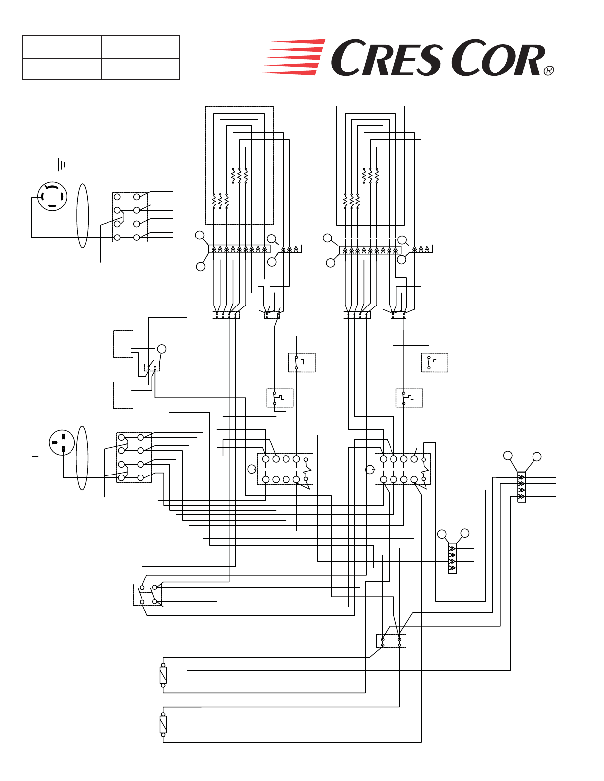
Ovens
FL-2340
Rev. 6 (2/09) Page 10 of 12
L15-20P
6000 WATT
G
X
Z
Y
L3
L2
L1
(1) JUMPER
3 WIRE
3 PHASE
AS SHOWN
TERMINAL BLOCK
5925 Heisley Road • Mentor, OH 44060-1833
Upper
Oven
104
250 Watt
Heaters (3)
105
103
100
101
1000 Watt
8
4
7
3
6
2
5
1
Heaters (3)
102
979899
949596
P12
949596979899100
1
939291908988878685
P11
P10
101
102
9
1
P9
104
103
848382
Lower
Oven
or single oven
105
P8
3
P7
1
114
106
106
112
113
1000 Watt
Heaters (3)
107
108
107
108
115
109
109
116
110
111
250 Watt
Heaters (3)
110
111
117
P6
112
113
114
115
116
117
9
71727476777879808181
P5
3
1
757370
1000CH SERIES
WIRING DIAGRAM
73
70
75
71
939291
TB8
61
908988
TB7
60
66
69
85
828384
87
86
TB6
124
123
8079787776
TB5
57
74
72
TB4
56
TB3
68
67
125
126
Upper and Lower Ovens
6-30P
6000 WATT
L2
G
L1
SINGLE
PHASE
FAN
VENT
FAN
VENT
L1 L2
(2) JUMPER'S
AS SHOWN
208
240
SERVICE SWITCH
CLOSED 208 V
123
59
64
616059
2T13
2
L1
124
HL 2
58
126
HL 4
54
125
HL 3
55
62
58
120
63
T4
C2
3
L4
4
53
TB1
9
L1
567
121
54
55
56
57
19
2T13
2344
8
128
118
20
52
127
122
14
10
To upper control panel
P3
P4
12
122
11
121
47
120
16
119
or single control panel
To lower control panel
P2
P1
14
14
14
14
15
15
15
15
20
20
20
20
23
23
23
23
19
19
19
19
24
24
24
24
21
21
21
21
18
18
18
18
TB2
119
18
118
HL 1
8
2
4
7
1
3
6
2
2
5
1
1
69
68
66
67
65
62
63
64
9
65
C1
123
3 A
FUSE
128
10
3 A
FUSE
127
Call Toll-free: 877-CRES COR (273-7267) • Fax: 800-822-0393 • www.crescor.com

5925 Heisley Road • Mentor, OH 44060-1833
WIRING DIAGRAM FOR 1000CH SERIES, Control Panel
Ovens
FL-2340
Rev. 6 (2/09) Page 11 of 12
Relay
4342 44 45
50
Upper control panel
47
46
45
Thermostat
Hold
41
Timer
40
4243
Roast
Hold
OUT
L2
39
38
39
40
41
46
A G
M
L1
Thermostat
Roast
44
4948
48
49
50
51
Relay
26
27
3433
37
25
24
26
Thermostat
Hold
32
Timer
30
3334
Roast
Hold
OUT
L2
31
29
31
30
32
25
3635
GA
M
L1
Thermostat
Roast
27
35
36
37
28
Lower control panel
A
38
Upper
Power
Switch
17
17
Fan
16
P4
122
121
120
119
Switch
P3
12
11
47
16
51
Lower
P2
11
12
P1
14
14
14
14
15
15
15
15
20
20
20
20
23
23
23
23
19
19
19
19
24
24
24
24
21
21
21
21
18
18
18
18
Power
22
21
29
Switch
Fan
Switch
A
28
22
15
23
Call Toll-free: 877-CRES COR (273-7267) • Fax: 800-822-0393 • www.crescor.com
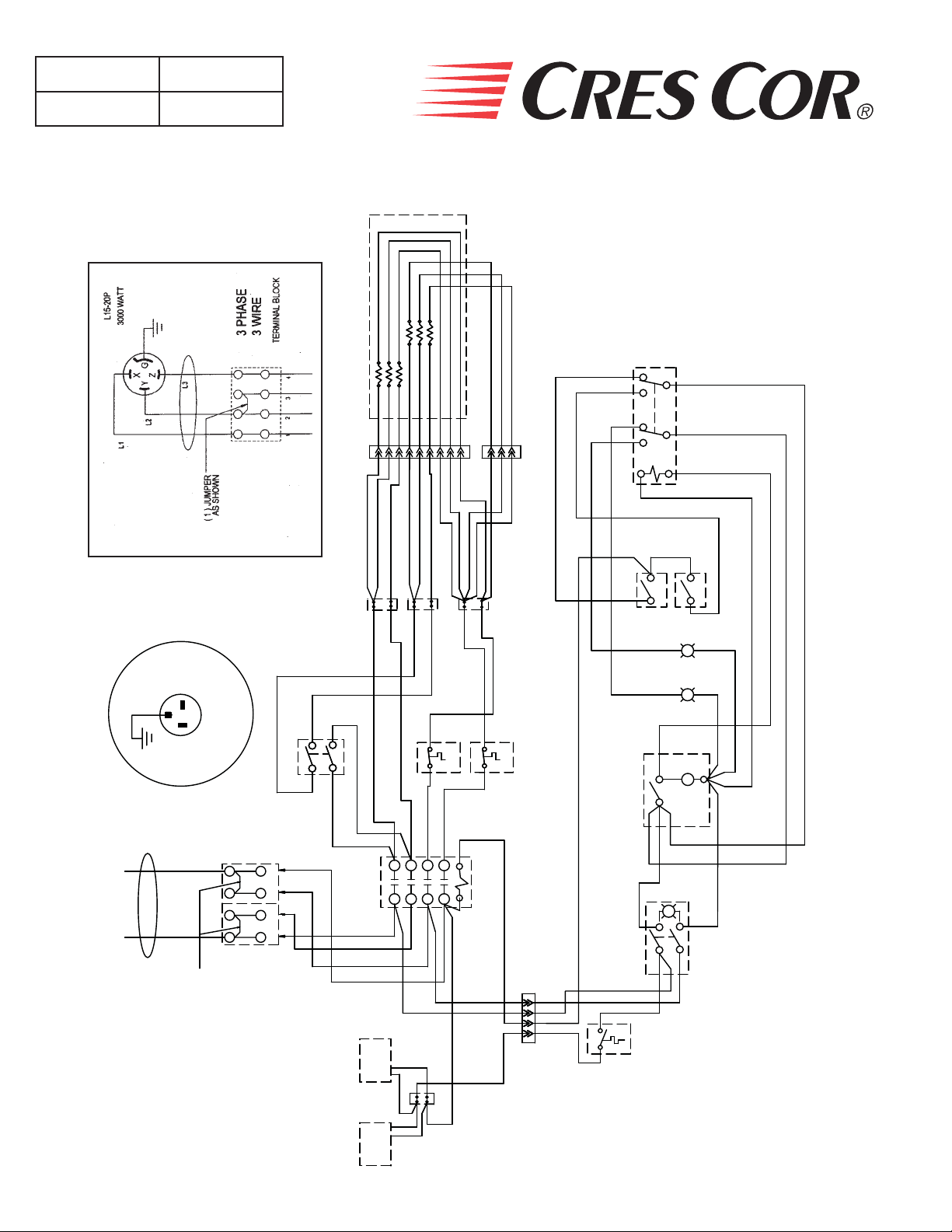
Ovens
FL-2340
Rev. 6 (2/09) Page 12 of 12
WIRING DIAGRAM FOR 1000CH-SPLIT SERIES
5925 Heisley Road • Mentor, OH 44060-1833
103
104
105
979998
102
100
101
94
95
96
94
96
95
999897
100
101
93
92
91
908988
87
86
104
103
102
85
105
84
83
82
RELAY
6
39
9
3
44 45
4
7
43
1
42
50
41 40
B
A
6-20P
3000 WATTS
208/240 VOLT
JUMPERS AS
SINGLE PHASE
SHOWN
64
69
SWITCH
65
66
4
3
2
1
93
929190
61
65
CONTACTOR
FAN
VENT
46
47
89
8786838285
88
69
66
60
123
124
123
124
84
45
HOLD T'STAT
43
44
COOK T'STAT
G
42
49
A
48
48
49
M
50
L1
51
51
12
61
1
64
T1
L1
121
HI LIMIT
60
T2
L2
2
3
HI LIMIT
59
58
OUT
L2
TIMER
40
38
59
58
120
T4
T3
L3
L4
4
53
122
118
POWER
122
120
121
119
11 12
47
16
17
39
A
38
SWITCH
11
17
HI LIMIT
16
119
118
FAN
VENT
Call Toll-free: 877-CRES COR (273-7267) • Fax: 800-822-0393 • www.crescor.com
 Loading...