

Page 1
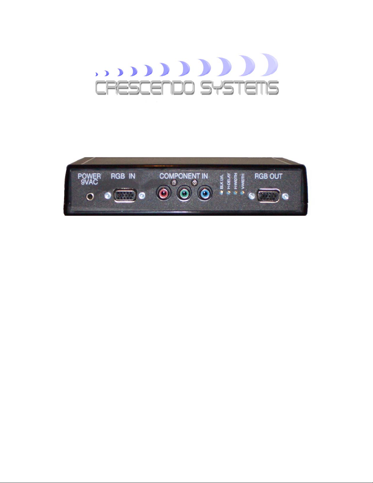
RTC2000 Reverse Transcoder Users Manual
Introduction
The Crescendo-Systems RTC2000 reverse transcoder is a highly flexible device to
convert aYPrPb component signal into a RGBHV signal. The RTC2000 will support
video formats in 480i, 480p, 576i, 576p, 720p and 720p, 1080i23/25/30 and
1080p50/59/60. It also supports computer resolutions up to UXGA (1600 x 1200
@75Hz) for the RGB pass through function.
The RTC2000 supports both color conversions for 480p (SD) and 720p/1080i (HD) in
order to provide optimum color fidelity. Although the required conversions are nearly
identical, the difference cannot be ignored when optimum quality is pursued. The
selection is automatically made based on line frequency but can be set manually if so
desired.
Although most display devices automatically fix the reference level on the incoming
video signal, the RTC2000 has an adjustable black level for optimum use in DC coupled
video systems. Additionally, the possibility exists to offer the user manual control over
the horizontal sync delay and the horizontal and vertical sync widths.
RTC2000 users manual v1.0
Page 2

Warning! Using incorrect scan-frequencies can seriously damage your TV or front
projector, Crescendo-Systems takes no responsibly implied or otherwise and CrescendoSystems’ total liability to any customer for any and all claims relating to the use of the
RTC2000 shall not exceed the total amount paid by such user to Crescendo-Systems for
obtaining this product.
Specifications
The RTC2000 offers the user total flexibility and has the following specifications and
features:
• High-Bandwidth component to RGBHV transcoder with RGBHV pass-through
• Manual or automatic color conversion selection for SD and HD color space
• Accepts bi- and tri-level sync and is Macrovision compatible (except 480i, 567i)
• Completely removes all sync from the output
• Accepts the following component video formats on the component input:
• 480i
• 480p
• 576i
• 576p
• 720p
• 1080i23/25/30
• 1080p50/59/60
• Accepts up to UXGA (1600 x 1200 @75Hz) on the RGB input
• Adjustable black level for DC coupled systems
• Automatic or manual setting of H-delay, H-width, V-width, H-polarity and V-
polarity
• Drives cables of up to 50 feet (16m)
• Component (YPrPb) input on three color-coded RCA connectors.
• Pass-through input and RGB output on a female VGA connector. The gain equals
unity when driving 75 Ohm
• Sync outputs have a 75 Ohm source resistance and can drive a 75 Ohm load
Included in this package are one RTC2000 and one external power supply. The manual
with warrantee statement will be sent by email and optionally can be directly downloaded
from the
Crescendo-Systems website.
RTC2000 users manual v1.0
Page 3

Setup
In order to successfully use your RTC2000 in just follow the simple steps outlined
below.
1. Make sure that your source device has the ability to correctly set the timing
needed by your display. If this is not the case, do not use the RTC2000.
2. Connect the component output of your source to the component input of the
RTC2000. Additionally, you can connect a RGBHV signal to the pass through
input of the RTC2000, which will be activated by the presence of a sync signal.
3. Connect the RTC2000 to your display using the VGA output connector.
4. Connect the power supply to the transcoder. Use only the supplied unit or an
exact equivalent.
Additional features The RTC2000 is shipped in full automatic mode with the following features:
• The input is auto selected based on the presence of a sync signal on the RGB pass
through input. If sync is present on the RGB port that input is selected, otherwise
the component input is selected.
• The color space is automatically selected based on the line frequency of the
incoming signal.
• The level of the backporch is set to zero volts. This level is only important in DC
coupled systems. Almost all display devices are AC coupled and the black level is
clamped internally, in which case the black level control will have no influence.
• The horizontal and vertical sync width and position are automatically selected
based on the incoming signal.
• The horizontal and vertical sync are set to negative polarity.
Normally the full automatic mode should work in most cases. If it does not, all of the
features mentioned above can be overruled manually. To do so the case has to be opened
and a number of jumpers changed. Before opening the case please remove the power
supply first. Remove the four screws at the bottom of the RTC2000 and lift the top of
the case. Inside is the printed circuit board of which an enlarged section is shown in
figure 1 below. On the PCB are three jumper blocks that can be used to customize the
various options of the RTC2000. A description of the jumpers is given below.
RTC2000 users manual v1.0
Page 4
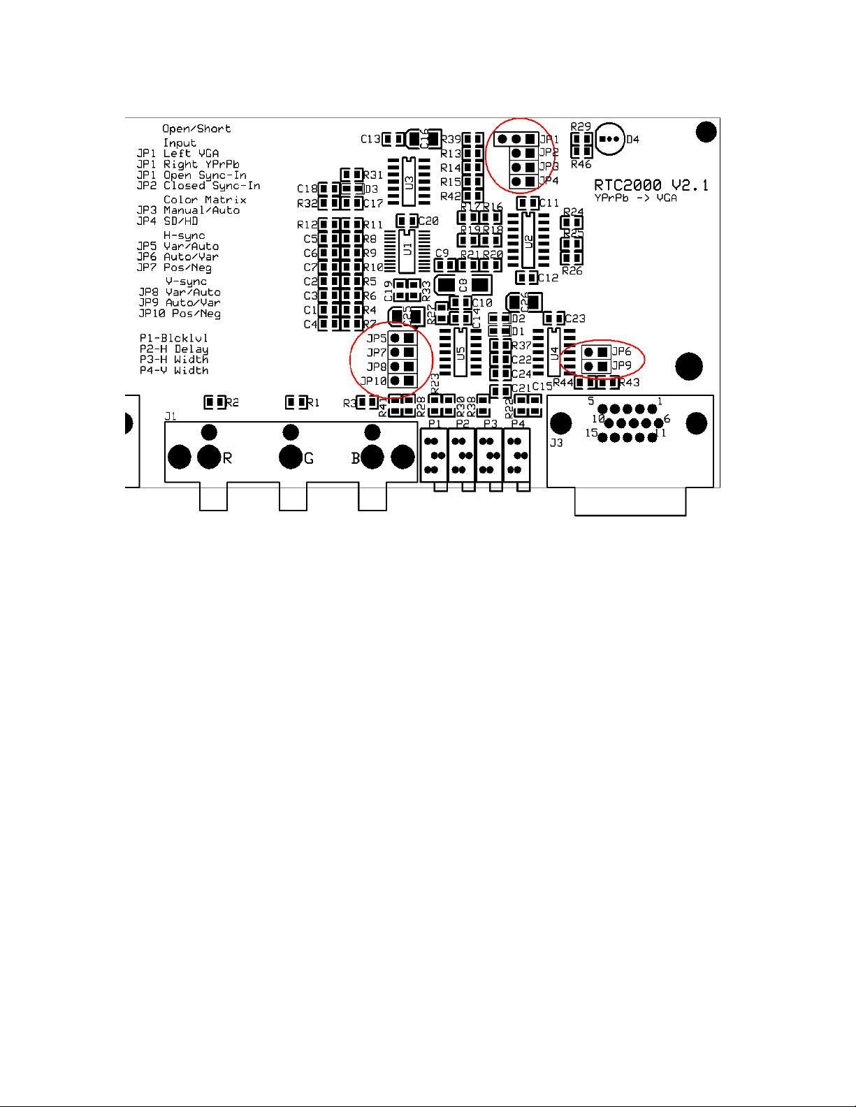
Figure 1 RTC2000 printed circuit board
JP1: Manual input select. Left two pins shorted selects VGA input. Right two pins
shorted selects component input. For automatic input select leave JP1 open.
JP2: For automatic input select JP2 has to be shorted, for manual input select keep JP2
open.
JP3: For automatic color space select JP3 should be shorted. Keep JP3 open for manual
color space selection.
JP4: Jumper for manual color space selection, open means standard definition color
space, shorted selects high definition color space. Warning: shorting JP3 and JP4
at the same can cause damage to the TCP2000.
JP5: For automatic horizontal sync selection this jumper should be shorted, leave open
to manually set the H-sync width and delay.
JP6: For manual horizontal sync selection this jumper should be shorted, leave open
otherwise. The two 25-turn potmeters on the back labeled H-delay and H-width
can now be adjusted with a small screwdriver in order to set the desired horizontal
sync delay and horizontal sync width. Turning the potmeters clockwise will
increase the value.
JP7: Short this jumper for negative horizontal sync at the output, leaving it open sets a
positive horizontal sync.
JP8: For automatic vertical sync selection this jumper should be shorted, leave open to
manually set the V-sync width.
RTC2000 users manual v1.0
Page 5

JP9: For manual vertical sync selection this jumper should be shorted, leave open
otherwise. The 25-turn potmeter on the back, labeled V-width can now be
adjusted with a small screwdriver in order to set the desired vertical sync width.
Turning the potmeter clockwise will increase the value.
JP10: Short this jumper for negative vertical sync at the output, leaving it open sets a
positive vertical sync.
Warranty
Crescendo-Systems designs and builds all products with the highest of care and every
product should operate trouble-free for many years when used under normal operating
conditions. Therefore, every RTC2000 carries a 1-year no-hassle replacement warranty.
Should a warranty replacement be needed, please contact [email protected]
first.
RTC2000 users manual v1.0
 Loading...