

Page 1
Creotech Instruments S.A. tel. +48 22 233 10 27
ul. Gen. L. Okulickiego 7/9 e-mail: [email protected]
05-500 Piaseczno, Polska www.creotech.pl
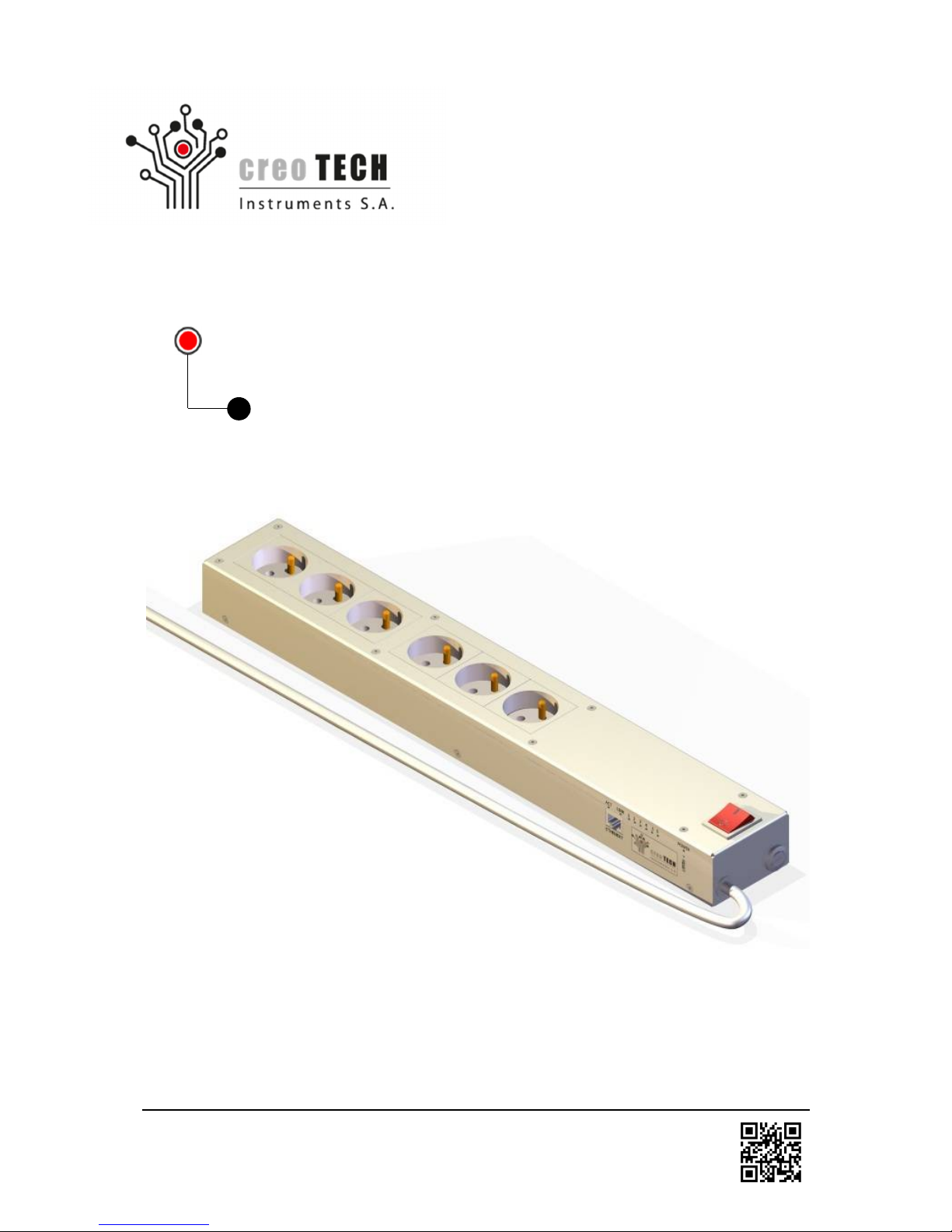
IP POWER STRIP (CTI-PS6/CTI-PS6-M)
v.3.5 (10.2015)
User`s manual
Page 2

2
Creotech Instruments S.A. tel. +48 22 233 10 27
ul. Gen. L. Okulickiego 7/9 e-mail: [email protected]
05-500 Piaseczno, Polska www.creotech.pl
Table of Contents
1. IDENTIFICATION AND SPECIFICATION OF PRODUCT 3
1.1 Product brand and type designation 3
1.2 General functions and range of applications 4
1.3 Producer and technical support center 4
1.4 Overview of the product 5
1.5 Technical drawing 6
1.6 Warranty 7
2. PREPARING THE PRODUCT FOR USE 8
2.1 Transport and storage 8
2.2 Safety precautions before use 8
2.3 Inventory 9
2.4 Unpacking 9
2.5 Preparatory work before installation 9
2.6 Installing and assembling 10
2.6.1 First start-up and configuration 10
2.6.1.1 Changing the network configuration of the PC for the first start-up procedure 11
2.6.1.2 Logging in through the web page 12
2.6.1.3 Configuration of the IP Power Strip Ethernet link 13
2.7 Caution about sequential switching 14
3. OPERATING INSTRUCTION 15
3.1 Controlling the power outlets through the web page 15
3.2 Schedule 16
3.3 Configuring the watchdog 17
3.4 Setting up user accounts 20
3.5 Firmware update 21
3.6 Measurement of power consumption (in CTI-PS6-M only) 22
3.7 Other configuration options of the IP Power Strip 23
3.8 Telnet protocol 24
3.9 SNMP protocol 25
4. MAINTENANCE AND CLEANING 28
4.1 Safety precautions 28
4.2 Maintenance and cleaning by users 28
4.3 Trouble-shooting 29
Page 3

3
Creotech Instruments S.A. tel. +48 22 233 10 27
ul. Gen. L. Okulickiego 7/9 e-mail: [email protected]
05-500 Piaseczno, Polska www.creotech.pl
1. Identification and specification of product
1.1 Product brand and type designation
Product designation:
Name: IP Power Strip
Model: CTI-PS6 / CTI-PS6-M
Serial number: See marking on the product
Hardware revision 1.4 (05.2013)
Firmware revision 1.32 (05.2013)
General product specification:
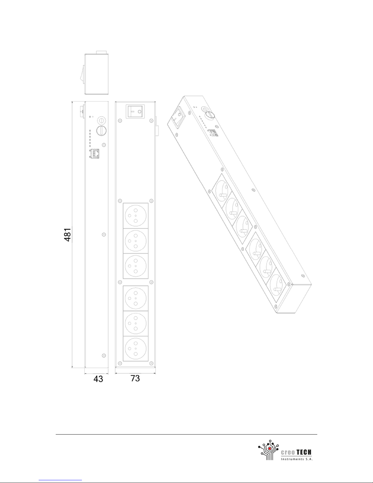
Product dimensions: 73 mm x 43 mm x 481 mm
Weight: 2.1 kg
Power cord length: 3 m
Housing material: Painted sheet metal DC 01
Protection rating: IP 2x
Power supply: 230 V AC 50 Hz
Number of power outlets: 6
Total output current: 10 A
Total output power: 2300 W
Power consumption: 3.2 W + 0.3 W per relay (control unit only)
Operating ambient temp.: 5oC - 40oC
Storage ambient temp.: -20oC - 70oC
Operating relative humidity: 10% - 95% without condensation
Pollution: Pollution degree 2
Altitude: up to 2000m
Built-in surge protection: YES (varistors)
Specification of digital outputs for alternating currents:
Output current per outlet: 8 A
Type of protection: Short-circuit-proof outputs (fuse)
Output delay time: Programmable (min. 0.2 s)
Commutation characteristics: NO relay, rated: 250 V AC / 8 A
Nominal voltage / current: 250 V AC / 8 A,
Durability: >3x10⁷ cycles
Behavior on interruptions and dips: All outputs OFF
Page 4

4
Creotech Instruments S.A. tel. +48 22 233 10 27
ul. Gen. L. Okulickiego 7/9 e-mail: [email protected]
05-500 Piaseczno, Polska www.creotech.pl
1.2 General functions and range of applications
The IP Power Strip (CTI-PS6) devices are stand-alone, network-manageable programmable control
units for six 230V power outlets. The control can be done remotely through webpage, SNMP or
telnet interfaces (available via 10Mbps Ethernet link). Watchdog function for response to the ping
command, allows to perform automatic reset of network devices. It is intended for use in home and
office environment and for indoor use only
This device allows:
- Protection of the connected circuits (varistors)
- Automatic hard reset of the connected devices by setting:
- Maximum power consumption (CTI-PS6-M only)
- The lack of response to the ping
- Scheduling switching sockets based on the calendar
- Remote control of each of the sockets with additional functions:
- Configure the default state of sockets after power failure
- Switching sockets on and off for defined time
- Built-in sequencing of the power outlets to prevent from large inrush currents
Exemplary applications:
- Remote switching on and off of non-easily accessible devices
- Hard-reset of network devices with sequential power-up
- Switching devices for pre-defined period of time
1.3 Producer and technical support center
Producer / technical support:
Name: Creotech Instruments S.A.
Address: ul. Okulickiego 7/9, 05-500 Piaseczno, Poland
E-mail: [email protected]
WWW: www.creotech.pl
Telephone: +48 22 233 10 27
Page 5
5
Creotech Instruments S.A. tel. +48 22 233 10 27
ul. Gen. L. Okulickiego 7/9 e-mail: [email protected]
05-500 Piaseczno, Polska www.creotech.pl
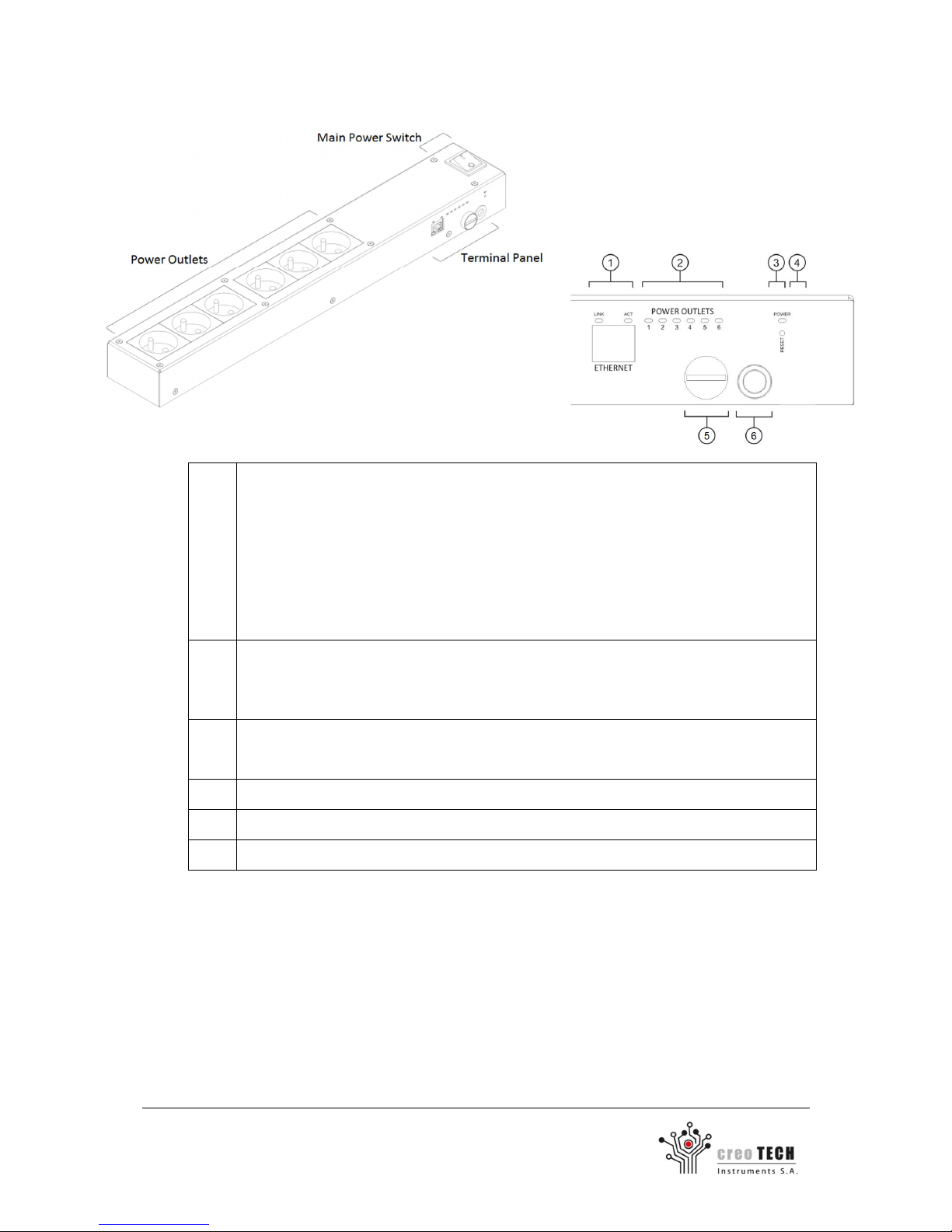
1.4 Overview of the product
1 Ethernet port: connects the IP Power
Strip to the local network using a CAT5 network
cable (or directly to the PC using included crossover patch cord for the first start-up)
Two Ethernet link status LEDs (LINK, ACT): indicate the state of the Ethernet
connection
LINK LED ON – The Ethernet link is up
LINK LED OFF – The Ethernet link is down
ACT LED ON – active data transfer
ACT LED OFF – no data transfer active
2 6 power outlet status LEDs:
indicate the state of the relays for each of the power outlets 1..6
OFF: relay OFF (no power on outlet)
ON: relay ON (power on outlet)
3 Control unit power LED: indicates the state of the control unit.
OFF – control unit OFF
ON – control unit ON
4 Reset button: restores the default settings of
the Ethernet interface (see 4.2)
5
Fuse
6 Power Cord
Page 6
6
Creotech Instruments S.A. tel. +48 22 233 10 27
ul. Gen. L. Okulickiego 7/9 e-mail: [email protected]
05-500 Piaseczno, Polska www.creotech.pl
1.5 Technical drawing
Page 7

7
Creotech Instruments S.A. tel. +48 22 233 10 27
ul. Gen. L. Okulickiego 7/9 e-mail: [email protected]
05-500 Piaseczno, Polska www.creotech.pl
1.6 Warranty
The limited warranty provided by Creotech Instruments S.A. applies only to products purchased for
commercial or industrial use in the ordinary course of business.
Terms of warranty
Creotech Instruments S.A. warrants this product to be free from defects in materials and
workmanship for a period of one year from the date of purchase. The obligation of Creotech
Instruments S.A. under this warranty is limited to repairing or replacing any such defective products.
This warranty does not apply to equipment that has been damaged by accident, negligence or
misapplication or has been altered or modified in any way. Repair or replacement of a defective
product does not extend the original warranty period.
Exclusions
The Creotech Instruments S.A. shall not be liable under the warranty if its testing and examination
disclose that the defect in the product does not exist or was caused by misuse, negligence, improper
installation or testing. Creotech Instruments S.A. shall not be liable under the warranty for
unauthorized attempts to repair or modify, broken warranty seal, wrong or inadequate electrical
voltage or connection, inappropriate on-site operation conditions, corrosive atmosphere, Acts of
God, fire, theft or installation contrary to Creotech Instruments S.A. recommendations or
specifications or in any event if the product’s serial number has been altered, defaced, removed or
any other damage caused by usage beyond the range of intended use.
Page 8

8
Creotech Instruments S.A. tel. +48 22 233 10 27
ul. Gen. L. Okulickiego 7/9 e-mail: [email protected]
05-500 Piaseczno, Polska www.creotech.pl
2. Preparing the product for use
2.1 Transport and storage
The product should always be kept in a safe and stable environment, both when in use and in
storage. In particular the product should be kept away from:
- direct sunlight,
- extreme changes in temperature or humidity,
- high levels of dust and pollution,
- fire,
- high temperature and humidity,
- heating and cooling equipment,
- locations where it might become wet,
- vibration and impact.
2.2 Safety precautions before use
This document presents important information intended to ensure safe and effective use of this
product. Please read this document carefully, and KEEP FOR FURTHER REFERENCE.
Safety warnings:
- This product is intended to use only in power supply network with protective earthing line.
- Shut down this equipment immediately if it produces smoke, a strange odor or unusual noise.
Immediately unplug the power cord and contact your dealer for advice.
- Never attempt to repair this product by yourself ( improper repair work can be dangerous).
- Never disassemble or modify this product (it may result in injury, fire or electric shock).
- Be sure to use the specified power source (connection of improper power source may cause fire or
electric shock).
- Never insert or disconnect the power plug with wet hands (it may result in electric shock).
- Do not allow foreign object to get into the device (it may lead to fire or electric shock).
- If water or other liquid spills over the device unplug the power cord immediately and then contact
your dealer or a service center for advice (continued usage may lead to fire or electric shock).
- Handle the power cord with care (improper handling may lead to fire or electric shock):
o Do not modify or attempt to repair the cord.
o Do not place any object on top of the cord.
o Avoid excessive bending, twisting and pulling.
o Do not place near devices emitting lots of heat and radiators.
o Ensure that the plug is clean before plugging it in.
o If the cord becomes damaged, stop using it and contact your dealer for advice.
- Do not use in locations subject to high humidity or dust levels (it may cause damage, fire or electric
shock).
- To ensure safety, please unplug this product prior to leaving it unused for an extended period of
time.
Page 9
9
Creotech Instruments S.A. tel. +48 22 233 10 27
ul. Gen. L. Okulickiego 7/9 e-mail: [email protected]
05-500 Piaseczno, Polska www.creotech.pl
2.3 Inventory
The complete product package should contain the following items.
Quantity
Item 1 CTI-PS6 or CTI
-
PS6-M IP Power Strip
1
1.5m crossover Ethernet patch cord for initial configuration
2.4 Unpacking
Confirm that the package includes all necessary parts. If the product is damaged or incomplete,
contact your dealer for assistance.
After unpacking, save the packaging materials so that they can be reused for further transport of the
product or dispose of them appropriately (please recycle).
2.5 Preparatory work before installation
Before installation make sure to acquire knowledge about the Ethernet infrastructure the power strip
will be operating in. In particular:
- Applicable IP subnet mask
- Default gateway
- Check for available IP addresses or check if the network allows DHCP service
Also make sure that you have a proper web browser installed if you intend to use the IP power strip
website. Supported browsers:
- Internet Explorer 9
- Mozilla Firefox 16 or higher
- Google Chrome 24 or higher
- Apple Safari 5.1 or higher
Page 10
10
Creotech Instruments S.A. tel. +48 22 233 10 27
ul. Gen. L. Okulickiego 7/9 e-mail: [email protected]
05-500 Piaseczno, Polska www.creotech.pl
2.6 Installing and assembling
IP Power strip should be placed in a solid, stable location (e.g. floor).
2.6.1 First start-up and configuration
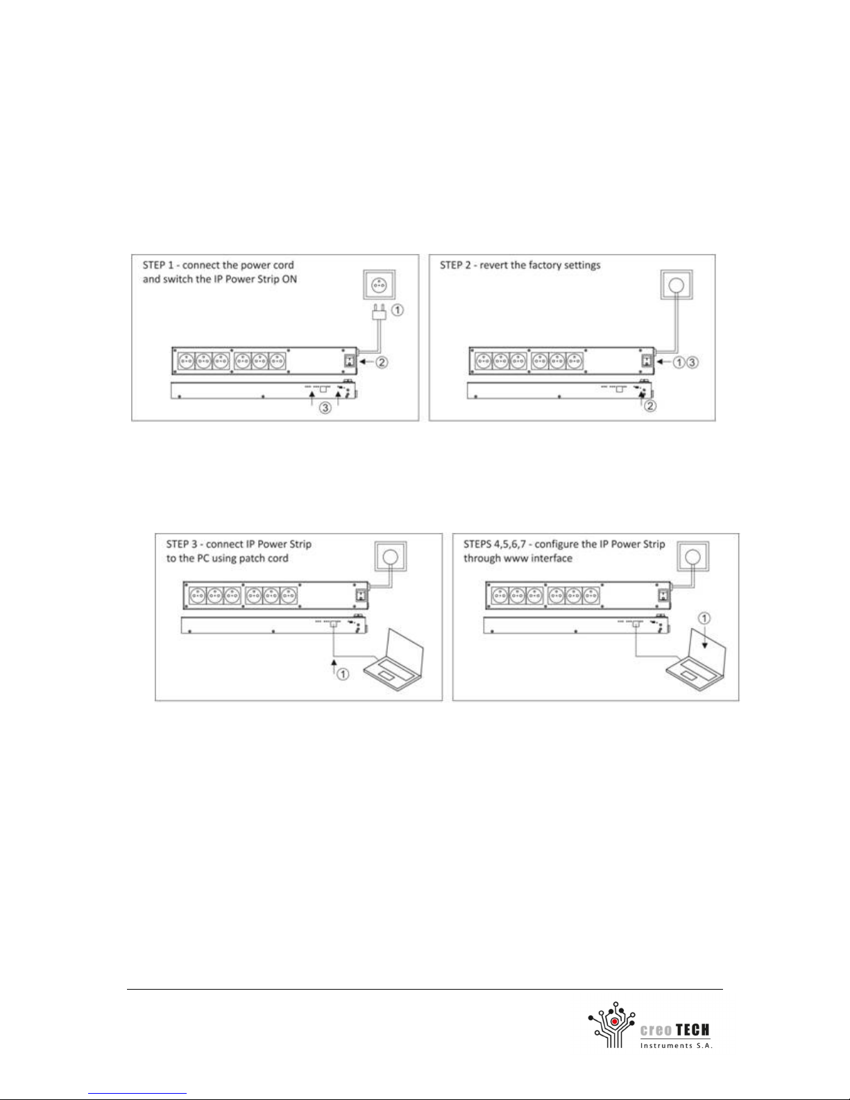
Before the IP Power Strip can be operated through network it is necessary to follow a fist-start-up
procedure:
1. Attach the power cord to the IP Power Strip and switch the main switch on. (The power
status LED should turn ON).
2. Restore the factory settings (refer to 4.2).
3. Connect the IP Power Strip and a PC computer directly using crossover Ethernet patch cord.
4. Modify the TCP/IP protocol settings in a PC to communicate with IP Power Strip using default
network settings. (see 2.6.1.1)
5. Log in to the IP Power Strip using a web browser and default login / password. (see 2.6.1.2)
6. Change the network settings of the IP Power Strip to comply with the requirements of a
target network. (see 2.6.1.3)
7. Save settings and reboot the IP Power Strip using Status tab (see 2.6.1.3).
Page 11
11
Creotech Instruments S.A. tel. +48 22 233 10 27
ul. Gen. L. Okulickiego 7/9 e-mail: [email protected]
05-500 Piaseczno, Polska www.creotech.pl
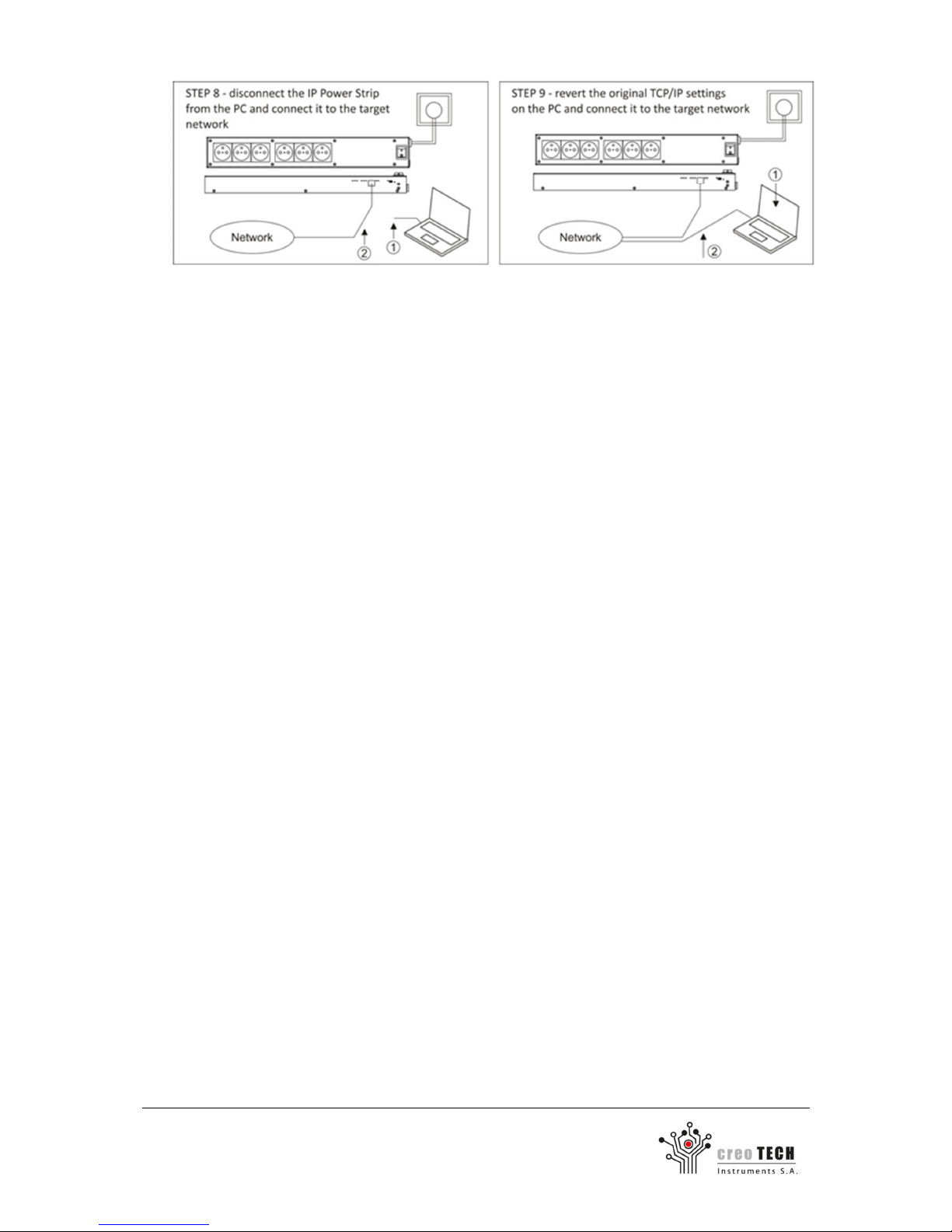
8. Disconnect the patch cord and connect the IP Power Strip to the target network cable.
9. Restore the TCP/IP protocol settings of the PC computer. Connect the PC to the target
network (wireless or wired connection).
10. Verify the configuration by logging in through the new Ethernet network.
11. Start regular operation of the IP Power Strip
2.6.1.1 Changing the network configuration of the PC for the first start-up
procedure
The factory settings of the IP Power strip network protocol are following:
IP address (static):
192.168.1.201
Login:
admin
Subnet mask:
255.255.255.0
Password:
123456
DHCP:
Disabled
Default outlet state:
all OFF
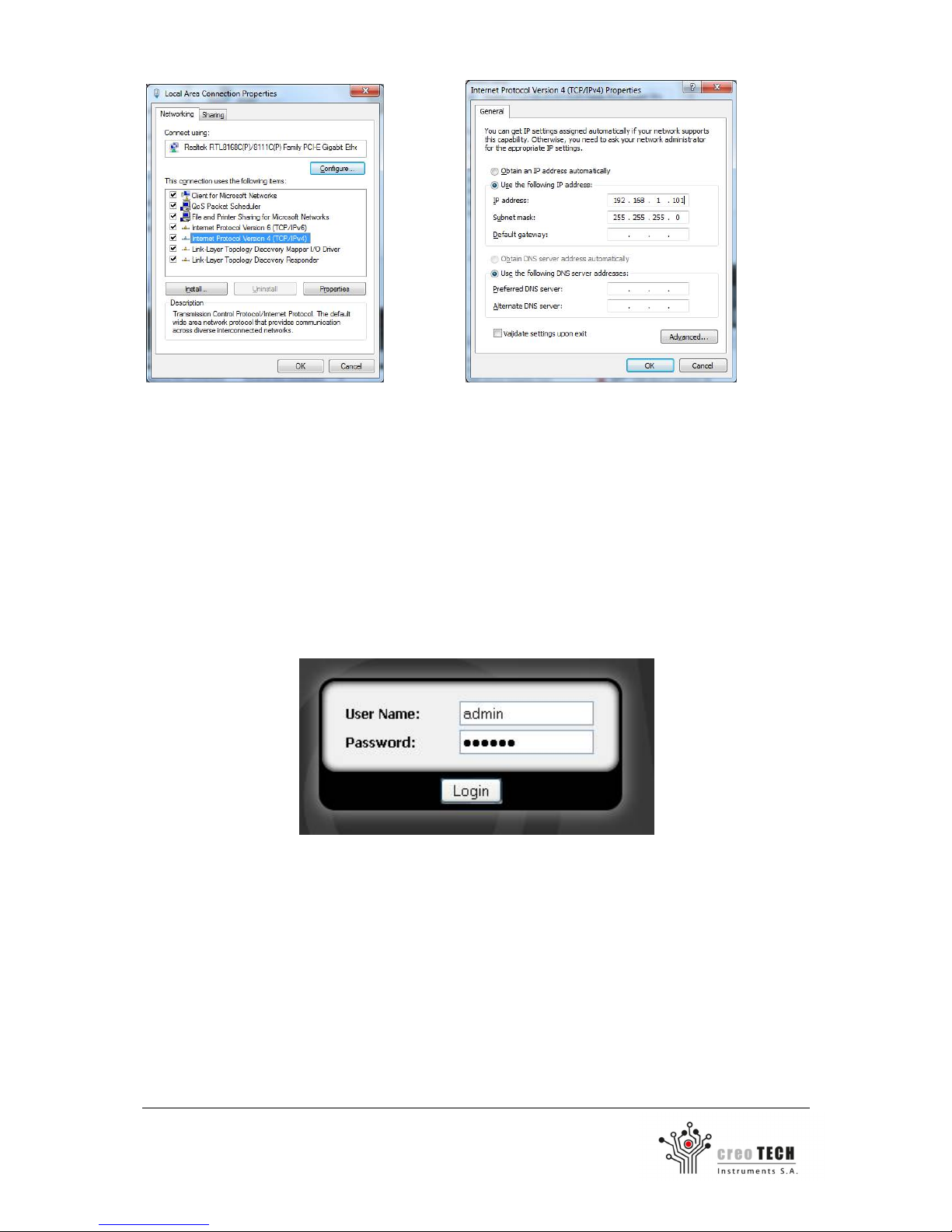
To communicate with IP Power Strip for the first time, it is required to change the network protocol
settings of the computer used for the first configuration of the IP Power Strip.
Before making any changes to the TCP/IP protocol settings of a PC please write down the current
configuration (especially: DHCP status, IP address, Subnet mask).
Access the local area network configuration panel.
For Windows 7:
Control Panel / Network and Internet / Network and Sharing Center / Change adapter settings
OR
Click Start button, type ncpa.cpl in the Search box and press Enter.
Open properties window of the active Local Area Connection (make sure it is wired not wireless) by
clicking right button on appropriate icon and selecting Properties.
Change the TCP/IPv4 protocol settings of the PC computer to the following:
IP address (static):
192.168.1.101
Default gateway:
None
Subnet mask:
255.255.255.0
DNS:
None
DHCP:
Disabled
Page 12
12
Creotech Instruments S.A. tel. +48 22 233 10 27
ul. Gen. L. Okulickiego 7/9 e-mail: [email protected]
05-500 Piaseczno, Polska www.creotech.pl
2.6.1.2 Logging in through the web page
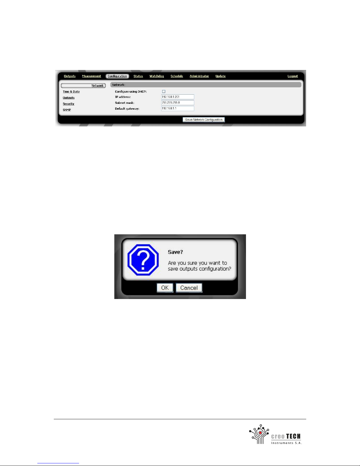
In a web browser (section 2.5 contains the list of supported browsers) type the IP address of IP
Power Strip:
- During first start-up procedure: http://192.168.1.201
- During regular operation: previously configured IP address
The welcome page of IP Power Strip will be displayed.
IP Power Strip lets you create six user accounts and one administrator account. The administrator has
access to all settings, can create user accounts and assign them privileges.
To log in type the username and password and click Log in:
- During first start-up procedure: admin / 123456
- During regular operation: previously configured user name and password. (If password or
username is lost see: Troubleshooting)
Caution: due to security reasons, it is important to immediately change the default password.
Page 13
13
Creotech Instruments S.A. tel. +48 22 233 10 27
ul. Gen. L. Okulickiego 7/9 e-mail: [email protected]
05-500 Piaseczno, Polska www.creotech.pl
2.6.1.3 Configuration of the IP Power Strip Ethernet link
After successful logging in, select Configuration tab and then from the menu on the left, select a
Network group.
Change the following parameters to comply with the requirements of the target Ethernet network
the IP Power Strip is intended to be used in. Static IP configuration can be used (preferable) or a
DHCP:
- IP Address (static), Subnet mask, Default Gateway.
- Enable Configure using DHCP option for DHCP configuration.
Double-check the new configuration settings.
After all the changes were made correctly press Save Network Configuration.
You will be asked to confirm the changes.
After pressing OK the device will countdown 10 seconds during which the device will reset and the
new settings will take effect.
Verify the configuration (it might be useful to check the MAC address of the IP Power Strip for easier
identification of the assigned IP address when DHCP is used).
Page 14

14
Creotech Instruments S.A. tel. +48 22 233 10 27
ul. Gen. L. Okulickiego 7/9 e-mail: [email protected]
05-500 Piaseczno, Polska www.creotech.pl
2.7 Caution about sequential switching
It is recommended to thoughtful connect the device to the appropriate socket number because of
the sequential switching outputs. Sequential switching sockets, starting from number 1 through 6
(excluding devices that has power-up state set to off) is a useful feature as it helps prevent large
inrush current. However, it carries certain consequences which users need to be aware of when using
specialized equipment or watchdog IP function.
If in managed network, it is important that any device was switched on before the other, it should be
connected to the socket with a lower number than the rest of the devices.
If the IP watchdog is used, it may be important that device which connects other devices to the
network (such as a router), was turned on first. This prevents a scenario where network devices will
turn on before the router and before they are connect to the network, they will be reset by the
watchdog IP.
Page 15
15
Creotech Instruments S.A. tel. +48 22 233 10 27
ul. Gen. L. Okulickiego 7/9 e-mail: [email protected]
05-500 Piaseczno, Polska www.creotech.pl
3. Operating instruction
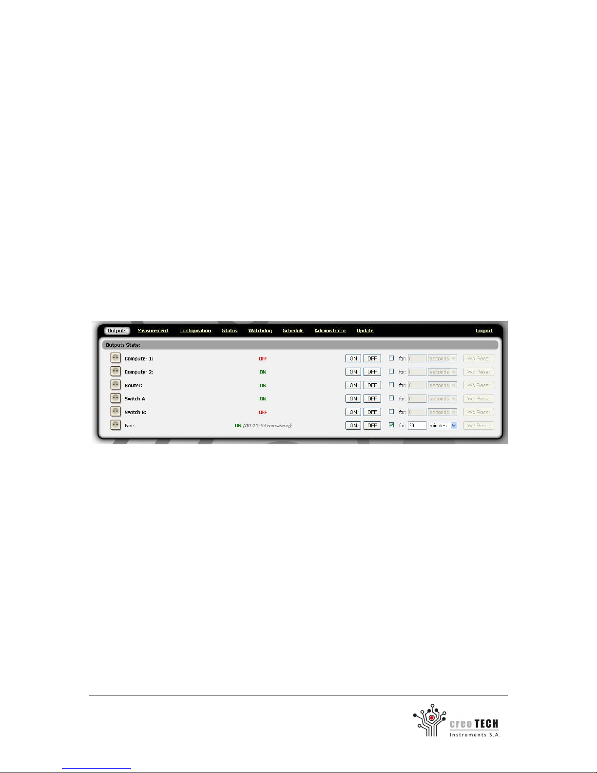
3.1 Controlling the power outlets through the web page
Log in to the IP Power Strip.
Select Outputs tab.
Each output has certain number, name (configurable in Configuration tab) and state indicator.
WD Reset button is used to reset the watchdog of the socket if it has been turned off by it. Details
can be found in Section 3.3.
It is possible to manually change the state of each outlet:
- Permanently: by clicking ON or OFF buttons.
- For a specified period of time by additional selection of an appropriate option in Outputs
tab.
- By setting up a schedule for each of the sockets using the weekly schedule (described in
Section 3.2).
Page 16
16
Creotech Instruments S.A. tel. +48 22 233 10 27
ul. Gen. L. Okulickiego 7/9 e-mail: [email protected]
05-500 Piaseczno, Polska www.creotech.pl
3.2 Schedule
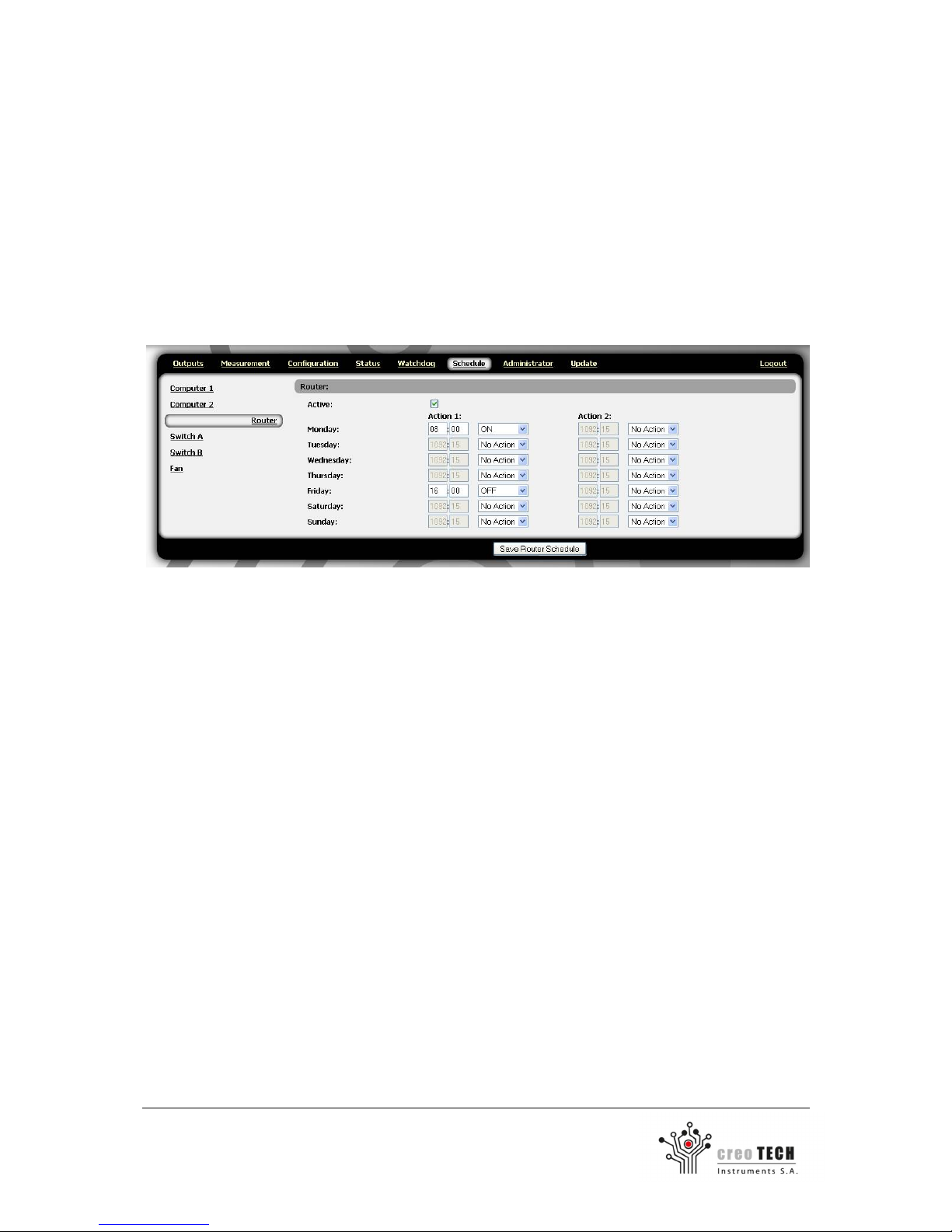
IP Power Strip lets you program weekly actions for each of the sockets.
Week scheduler can be found in Scheduler tab. To set the action for the socket you must first check
the Active checkbox in outlet tab that you want to set up. You can set two action for each socket per
day. Possible actions are: turning on, turning off and toggle the state of socket.
For example, if socket named “Router” should turn on Mondays at 8:00 and turn off at 16:00 on
Friday, then the fields should be set as shown in the picture below.
Page 17

17
Creotech Instruments S.A. tel. +48 22 233 10 27
ul. Gen. L. Okulickiego 7/9 e-mail: [email protected]
05-500 Piaseczno, Polska www.creotech.pl
3.3 Configuring the watchdog
IP Power Strip allows you to automatically reset connected devices. Reset can be triggered by lack of
response to the ping or exceeded power consumption of the socket (only for PS6-M). Each socket can
be configured independently.
Go to Watchdog tab.
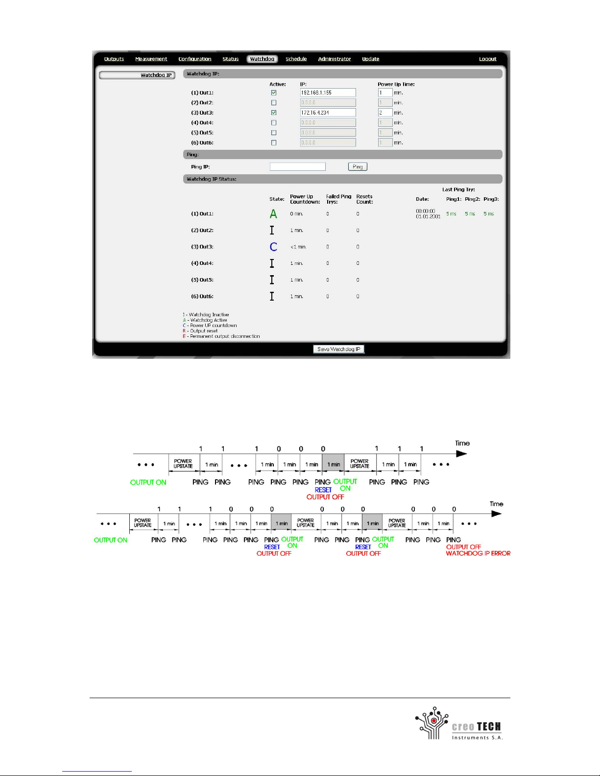
Watchdog IP
From the menu on the left, select an Watchdog IP group.
Activate the Watchdog IP function for the output by checking the Active checkbox.
Configure the IP address at which the device should respond to the ping.
IP Power Strip will periodically check whether the address responds to the ping. After three
unsuccessful attempts, the device will be hard reset (socket will be turned off for about one minute).
In the Power Up Time enter the time that IP power strip has to wait after resetting the device, before
it starts sending ping to the device again.
When three attempts to reset fail, the output will be turned off permanently.
After a watchdog alarm, to restore the normal functioning of the socket, go to Outputs and press the
Reset WD button.
IP watchdog work can be seen on the bottom of the webpage where you will find the information on
the current status of its operations for each of the sockets. These conditions are updated once per
minute, after sending and receiving the ping command to all outlets, so sometimes shown condition
may be out of date.
State - this parameter refers to the current state of IP watchdog action, it can take one of the
following conditions
o I - watchdog inactive
o A - watchdog active
o C - Power up countdown
o R - Output reset
o E - Permanent output disconnection
Power Up countdown - countdown power-up state, the time remaining to send the first ping
after turning on the socket
Failed Ping tries - the number of ping lost in a row, when it reaches the value of 3, socket will
be restarted
Reset Count - the number of times socket was restarted since the last answer to the ping
Last Ping Try - information about the last response to sent ping
Page 18
18
Creotech Instruments S.A. tel. +48 22 233 10 27
ul. Gen. L. Okulickiego 7/9 e-mail: [email protected]
05-500 Piaseczno, Polska www.creotech.pl
The figure below show two examples of how IP Watchdog works. Above the time axis are shown
device’s response to the ping, "1" means that the device answered, "0" that it did not. Under the
time axis are shown the actions performed by IP power strip. In the first case, the device stopped
responding to the ping command so it was reset and then it started working again. In the second
case, three times the hard reset didn`t help, so the socket was turned off permanently.
Page 19
19
Creotech Instruments S.A. tel. +48 22 233 10 27
ul. Gen. L. Okulickiego 7/9 e-mail: [email protected]
05-500 Piaseczno, Polska www.creotech.pl
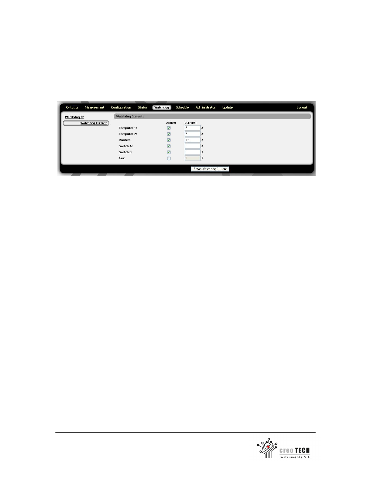
Watchdog Current (in CTI-PS6-M only)
From the menu on the left, select a Watchdog Current group.
Activate the current watchdog function for the output by checking the Active checkbox.
Set the maximum current consumption above which the socket will be turned off.
After a watchdog alarm, to restore the normal functioning of the socket, go to Outputs and press the
Reset WD button.
Page 20
20
Creotech Instruments S.A. tel. +48 22 233 10 27
ul. Gen. L. Okulickiego 7/9 e-mail: [email protected]
05-500 Piaseczno, Polska www.creotech.pl
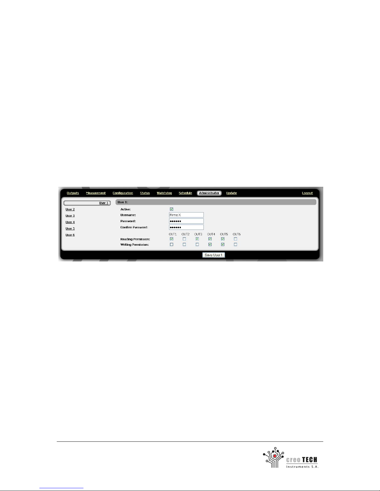
3.4 Setting up user accounts
IP Power Strip allows you to create 6 user accounts with limited rights. Each user have assigned rights
for each of the sockets separately. One of three levels of permission can be set: the ability to
configure the socket (writing permission), the ability only to check the state of socket (reading
permission) and lack of access to information about the output. User with reading permission can see
whether the outlet is turned on or off, and what actions are planned for him. With writing permission
you can change the state of the socket, giving them names, set the watchdog and action in schedule.
Only administrator account can create users and give them permission.
Go to Administrator tab.
From the menu on the left to select which user account you want to configure. To activate user
account, check the Active checkbox.
Enter the username, password, and set access rights to the sockets.
The user will be able to change his password.
Certain actions are reserved only for the administrator account:
Resetting the IP power strip
Creating user accounts and giving them permission
Firmware update
Setting the network configuration and the current time
Page 21
21
Creotech Instruments S.A. tel. +48 22 233 10 27
ul. Gen. L. Okulickiego 7/9 e-mail: [email protected]
05-500 Piaseczno, Polska www.creotech.pl
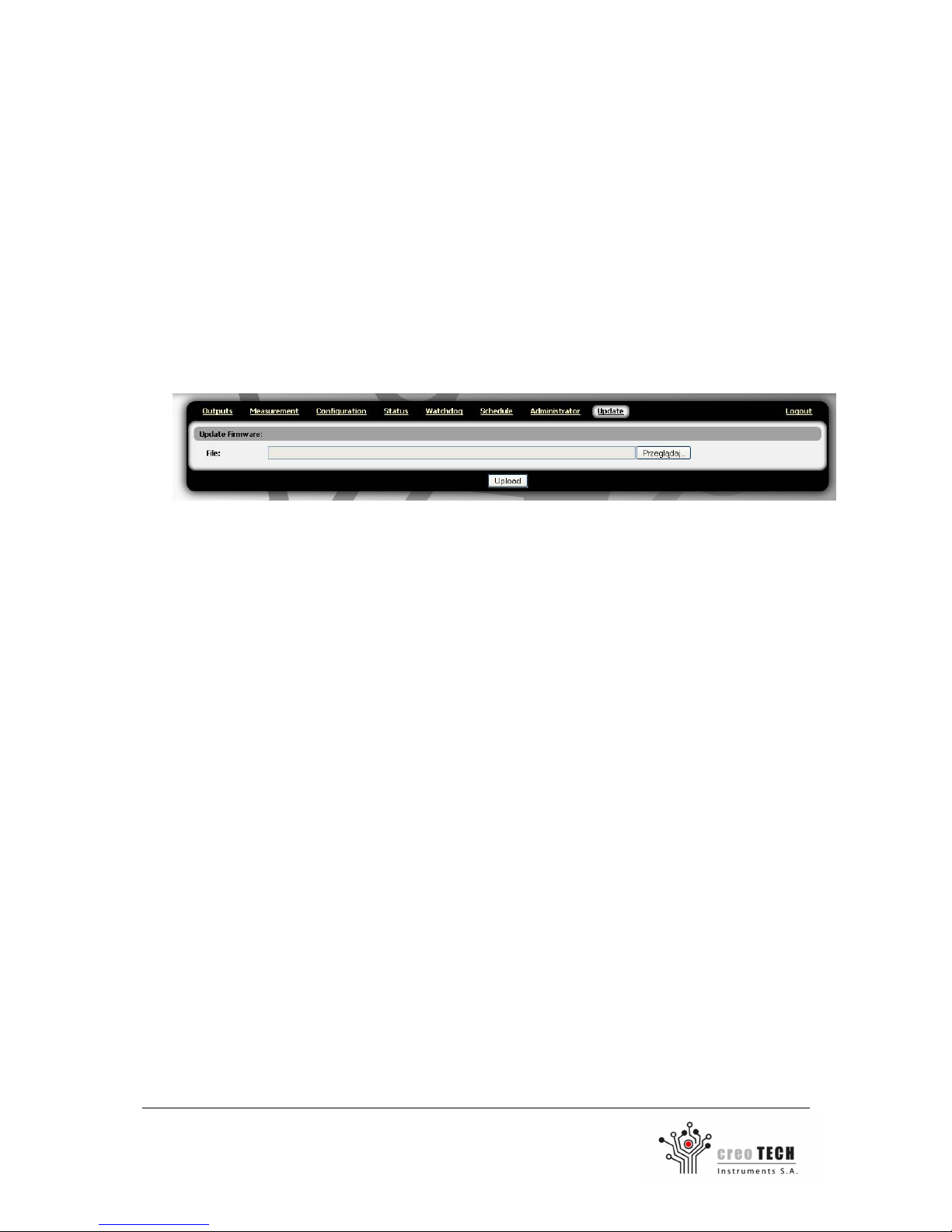
3.5 Firmware update
IP power strip allows the user to update firmware. This will allow to add new functionality in the
future. This operation is safe, because if a failure occurs, you can return to the factory version of the
firmware (see section 4.3).
To update the firmware, download the latest update from the website www.creotech.pl.
Log in to the IP power strip as administrator (only he has permission to update).
Go to Update tab.
Enter the path to the update file and then press the Upload button.
Update should take about one minute, after which the device will reset.
Page 22
22
Creotech Instruments S.A. tel. +48 22 233 10 27
ul. Gen. L. Okulickiego 7/9 e-mail: [email protected]
05-500 Piaseczno, Polska www.creotech.pl
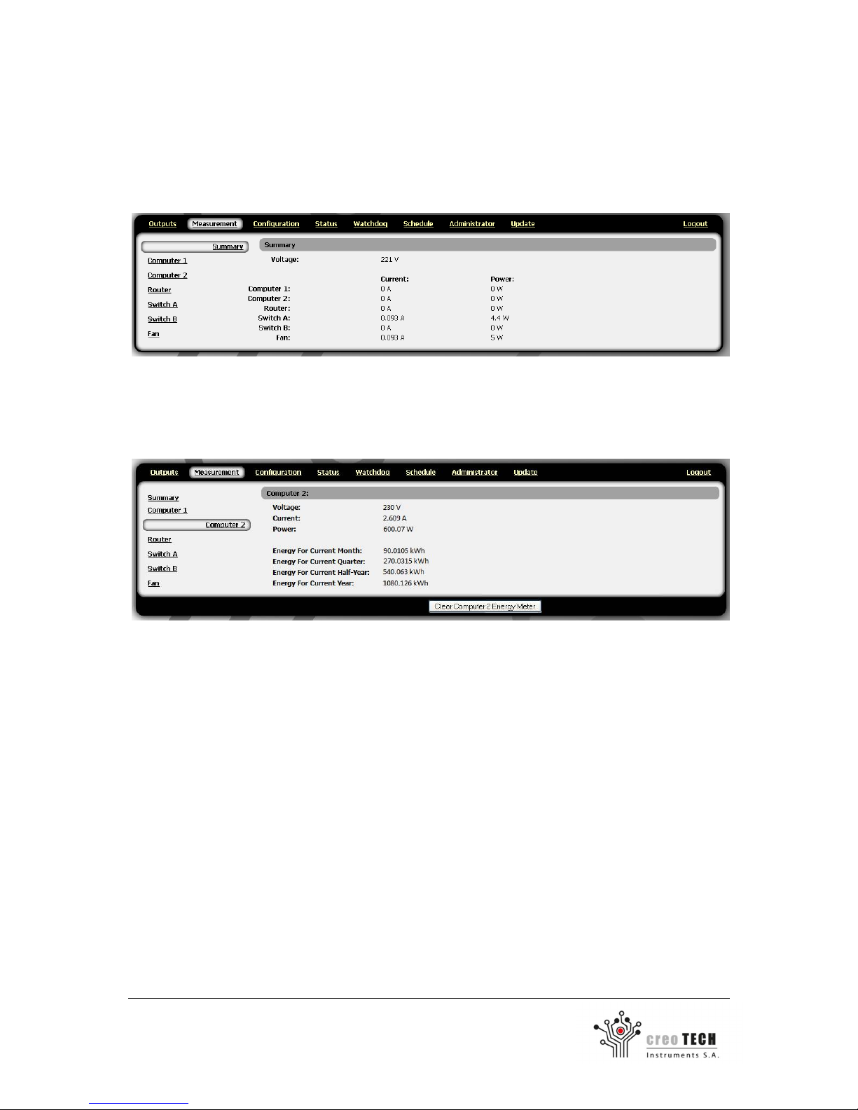
3.6 Measurement of power consumption (in CTI-PS6-M only)
IP power strip allows you to measure the electricity consumed by each output socket.
Go to Measurement tab.
Summary tab shows the current power consumption on the all outlets.
The tabs for each of the socket show: voltage, current and power measurement. It also shows power
consumption during the last month, three and six months and a year.
To reset the counter for the socket, press the Clear Energy Meter.
Page 23
23
Creotech Instruments S.A. tel. +48 22 233 10 27
ul. Gen. L. Okulickiego 7/9 e-mail: [email protected]
05-500 Piaseczno, Polska www.creotech.pl
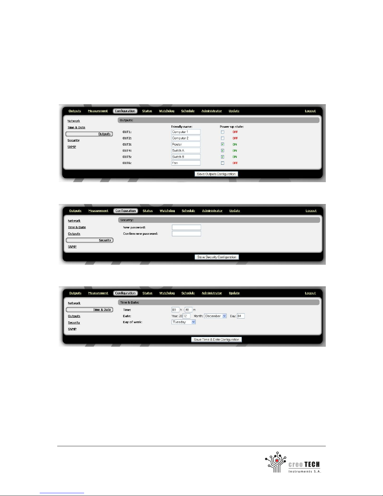
3.7 Other configuration options of the IP Power Strip
Select the Configuration tab and then select a Outputs group.
To specify individual name (e.g. Computer 1) for each outlet modify Friendly name property.
To modify the outlet state after the power-up, change Power-up state property. Box checked means
that the socket is turn on by default.
To change password, go to Security group.
To set the date, you must complete the fields in the Time & Date group.
Do not forget to apply the changes by clicking Save configuration button.
Page 24

24
Creotech Instruments S.A. tel. +48 22 233 10 27
ul. Gen. L. Okulickiego 7/9 e-mail: [email protected]
05-500 Piaseczno, Polska www.creotech.pl
3.8 Telnet protocol
In firmware version 1.34 Telnet protocol has been replaced with expanded version of SNMP
protocol. If there is a need to use the Telnet protocol, you should downgrade firmware to version
1.32 (section 3.5). Both the firmware can be found on the website: www.creotech.pl
Firmware 1.32 – Basic SNMP and Telnet
Firmware 1.34 and higher – Expanded SNMP and no Telnet
IP Power strip can be operated from the telnet protocol. Connection parameters are:
IP Address: previously set IP address of the IP power strip
Port number: 23
Below is a table with a list of commands.
Description Command
Status
output show
output on [output number] < delay >
output off [output number] < delay >
Configuring the
network
interface parameters
config dhcp <on/off>
config ip <ip adress>
config mask < network mask >
config gateway < default gateway>
Setting the default output
states
config output <111111>
Setting the friendly name
config outputname [output number] <name>
Configuring the watchdog
watchdog [output number] <ip adress>
Setting up user accounts
usermod [uid] <[r/w/-] [r/w/-] [r/w/-] [r/w/-] [r/w/-]
[r/w/-]> <user name> < password >
Show serial number
serial
Changing the password
passwd
Save the configuration
save
Reset the IP power strip
reset
Closing of the session
exit
Page 25
25
Creotech Instruments S.A. tel. +48 22 233 10 27
ul. Gen. L. Okulickiego 7/9 e-mail: [email protected]
05-500 Piaseczno, Polska www.creotech.pl
3.9 SNMP protocol
In firmware version 1.34 Telnet protocol has been replaced with expanded version of SNMP
protocol. If there is a need to use the Telnet protocol, you should downgrade firmware to version
1.32 (section 3.5). Both the firmware can be found on the website: www.creotech.pl
Firmware 1.32 – Basic SNMP and Telnet
Firmware 1.34 and higher – Expanded SNMP and no Telnet
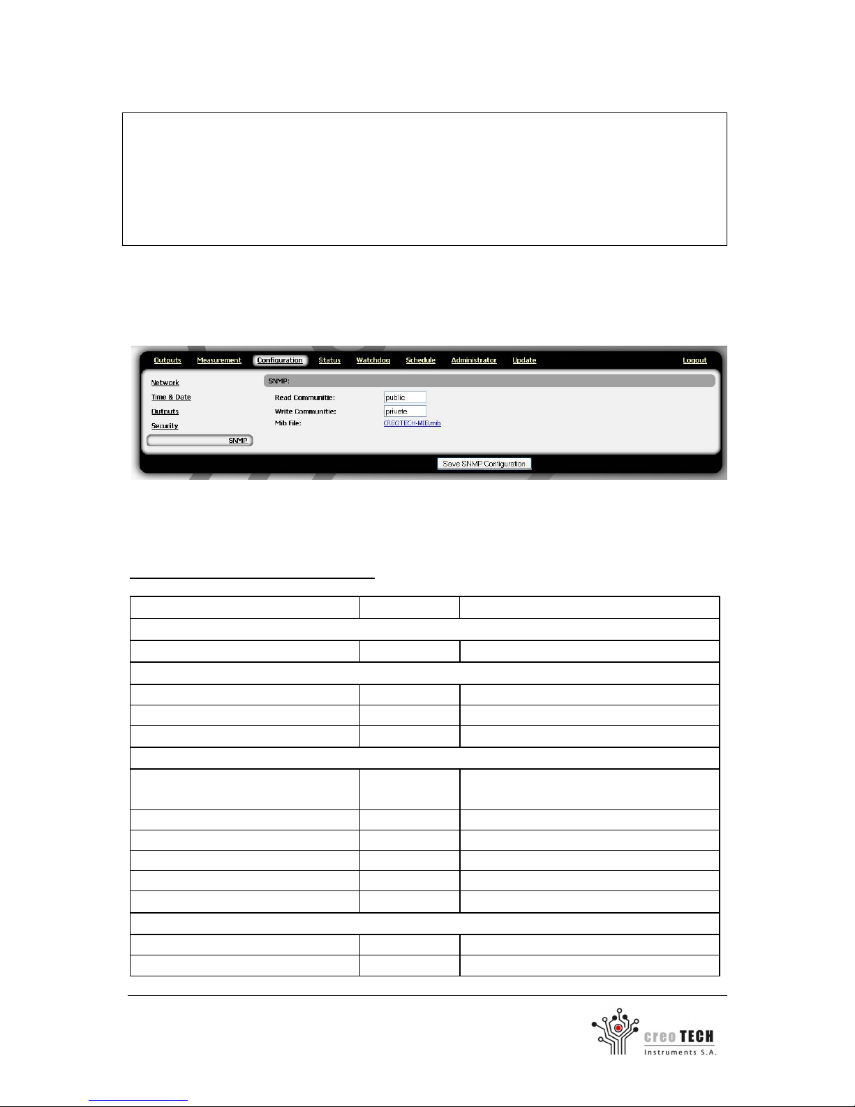
IP Power Strip lets you communicate with it using the SNMPv2 protocol.
Select the Configuration tab and from the menu on the left, an SNMP group.
You can set permissions to read and write, and view the MIB file.
Using SNMP, you can change, and check the status of the outputs.
Commands for Firmware 1.34 and higher
OID Type Description
Device Reset
.1.3.6.1.4.1.39525.1 INTEGER Set to positive value to reset
Device info
.1.3.6.1.4.1.39525.5.4 DisplayString Get device serial number
.1.3.6.1.4.1.39525.5.5 DisplayString Get device firmware
.1.3.6.1.4.1.39525.5.6 DisplayString Get device product ID
Networking
.1.3.6.1.4.1.39525.5.8.1.1 ENUM
Get & Set IP request method static(0),
dhcp(1)
.1.3.6.1.4.1.39525.5.8.1.2 OCTET STRING Get & Set IP
.1.3.6.1.4.1.39525.5.8.1.3 OCTET STRING Get & Set subnet mask
.1.3.6.1.4.1.39525.5.8.1.4 OCTET STRING Get & Set gateway
.1.3.6.1.4.1.39525.5.8.1.5.[1|2] OCTET STRING Get & Set DNS entries (2 rows)
.1.3.6.1.4.1.39525.5.8.1.6 OCTET STRING Get device MAC
Measurements (CTI-PS6-M only)
.1.3.6.1.4.1.39525.5.9.2.1.1.1.1.[1-6] INTERGER Get power outlet voltage RMS
.1.3.6.1.4.1.39525.5.9.2.1.1.1.2.[1-6] INTERGER Get power outlet current RMS
Page 26

26
Creotech Instruments S.A. tel. +48 22 233 10 27
ul. Gen. L. Okulickiego 7/9 e-mail: [email protected]
05-500 Piaseczno, Polska www.creotech.pl
.1.3.6.1.4.1.39525.5.9.2.1.1.1.3.[1-6] INTERGER Get power outlet active power
.1.3.6.1.4.1.39525.5.9.2.1.1.1.4.[1-6] INTERGER
Get power outlet 1 month energy
consumption
.1.3.6.1.4.1.39525.5.9.2.1.1.1.5.[1-6] INTERGER
Get power outlet 3 month energy
consumption
.1.3.6.1.4.1.39525.5.9.2.1.1.1.6.[1-6] INTERGER
Get power outlet 6 month energy
consumption
.1.3.6.1.4.1.39525.5.9.2.1.1.1.7.[1-6] INTERGER
Get power outlet 12 month energy
consumption
Outputs and watchdogs
.1.3.6.1.4.1.39525.5.10.1.1.1.[1-6] INTEGER Power outlet index
.1.3.6.1.4.1.39525.5.10.1.1.2.[1-6] ENUM State of the X power outlet off(0), on(1)
.1.3.6.1.4.1.39525.5.10.2.1.1.[1-6] ENUM
Which watchdog got triggered none(0),
reset(1), ip(2), temp(3), curr(4)
.1.3.6.1.4.1.39525.5.10.2.1.2.[1-6] INTEGER Reset watchdog true(1), false(2)
.1.3.6.1.4.1.39525.5.14.1.1.1.1.[1-6] ENUM
Temperature watchdog active true(1),
false(2)
.1.3.6.1.4.1.39525.5.14.1.1.1.2.[1-6] INTEGER Temperature watchdog triggering value
.1.3.6.1.4.1.39525.5.14.3.1.1.1.[1-6] ENUM IP watchdog active true(1), false(2)
.1.3.6.1.4.1.39525.5.14.3.1.1.2.[1-6] OCTET STRING IP watchdog address
.1.3.6.1.4.1.39525.5.14.3.1.1.2.[1-6] INTEGER IP watchdog boottime
.1.3.6.1.4.1.39525.5.14.3.2.1.1.[1-6] OCTET STRING IP watchdog status
.1.3.6.1.4.1.39525.5.14.3.2.1.2.[1-6] Counter32 IP watchdog failed tries
.1.3.6.1.4.1.39525.5.14.3.2.1.3.[1-6] Counter32 IP watchdog number of resets
.1.3.6.1.4.1.39525.5.14.3.2.1.4.[1-6] Counter32 IP watchdog countdown to powerdown
.1.3.6.1.4.1.39525.5.14.3.2.1.5.[1-6] INTEGER
IP watchdog latest ping result true(1),
false(2)
.1.3.6.1.4.1.39525.5.14.3.2.1.6.[1-6] INTEGER IP watchdog ping result true(1), false(2)
.1.3.6.1.4.1.39525.5.14.3.2.1.7.[1-6] INTEGER
IP watchdog newest ping result true(1),
false(2)
.1.3.6.1.4.1.39525.5.14.3.2.1.8.[1-6] INTEGER IP watchdog ticks till ping response 1
.1.3.6.1.4.1.39525.5.14.3.2.1.9.[1-6] INTEGER IP watchdog ticks till ping response 2
.1.3.6.1.4.1.39525.5.14.3.2.1.10.[1-6] INTEGER IP watchdog ticks till ping response 3
.1.3.6.1.4.1.39525.5.14.3.2.1.11.[1-6] OCTET STRING IP watchdog ticks last ping time
Commands for Firmware 1.32
OID outlets numbers:
1. .1.3.6.1.4.1.39525.11.1.2.0
2. .1.3.6.1.4.1.39525.11.1.2.1
3. .1.3.6.1.4.1.39525.11.1.2.2
4. .1.3.6.1.4.1.39525.11.1.2.3
5. .1.3.6.1.4.1.39525.11.1.2.4
6. .1.3.6.1.4.1.39525.11.1.2.5
Page 27

27
Creotech Instruments S.A. tel. +48 22 233 10 27
ul. Gen. L. Okulickiego 7/9 e-mail: [email protected]
05-500 Piaseczno, Polska www.creotech.pl
Command samples:
Turning on the first socket:
snmpset -c private -v2c <host> .1.3.6.1.4.1.39525.11.1.2.0 i 1
Turning off the fifth socket:
snmpset -v2c -c private <host> .1.3.6.1.4.1.39525.11.1.2.4 i 0
Check the state of the first socket:
snmpget -c public -v2c <host> .1.3.6.1.4.1.39525.11.1.2.0
Check the state of all sockets:
snmptable -c public -v2c <host> .1.3.6.1.4.1.39525.11
Check various values for SNMPv2:
snmpget -v2c -c public <host> .1.3.6.1.2.1.1.1.0
snmpget -v2c -c public <host> .1.3.6.1.2.1.1.2.0
snmpget -v2c -c public <host> .1.3.6.1.2.1.1.3.0
snmpget -v2c -c public <host> .1.3.6.1.2.1.1.4.0
snmpget -v2c -c public <host> .1.3.6.1.2.1.1.5.0
snmpget -v2c -c public <host> .1.3.6.1.2.1.1.6.0
snmpget -v2c -c public <host> .1.3.6.1.2.1.1.7.0
Page 28
28
Creotech Instruments S.A. tel. +48 22 233 10 27
ul. Gen. L. Okulickiego 7/9 e-mail: [email protected]
05-500 Piaseczno, Polska www.creotech.pl
4. Maintenance and cleaning
4.1 Safety precautions
See safety warnings (section 2.2) before using or maintaining the device.
Never open enclosure of the IP Power Strip (may cause electric shock).
4.2 Maintenance and cleaning by users
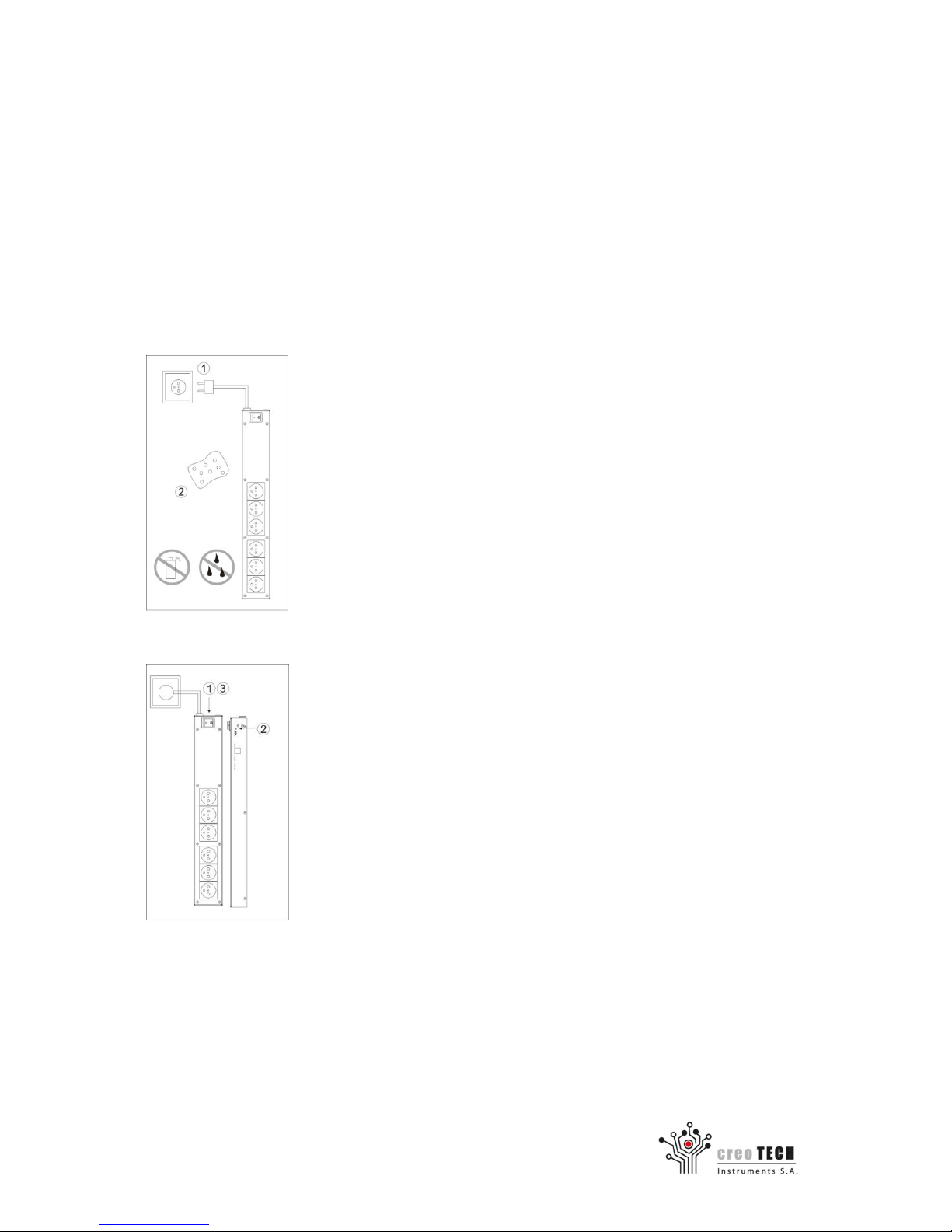
Cleaning the product:
1) Unplug the main power cord from the IP Power Strip.
2) Use a dry sponge to clean the product.
3) Do not use aerosol cleaners, alcohol, thinner, benzene etc. to clean
the product
4) Re-plug the power cord.
Restoring the default settings:
1) Switch the IP Power Strip off using main power switch.
2) Press and hold reset button (using a non-conductive item).
3) While holding reset button switch the IP Power Strip on using main
power switch.
4) When ACT and LINK leds blink, release the reset.
The default factory settings are:
IP address (static):
192.168.1.201
Login:
admin
Subnet mask:
255.255.255.0
Password:
123456
DHCP:
Disabled
Default outlet state:
all OFF
Page 29
29
Creotech Instruments S.A. tel. +48 22 233 10 27
ul. Gen. L. Okulickiego 7/9 e-mail: [email protected]
05-500 Piaseczno, Polska www.creotech.pl
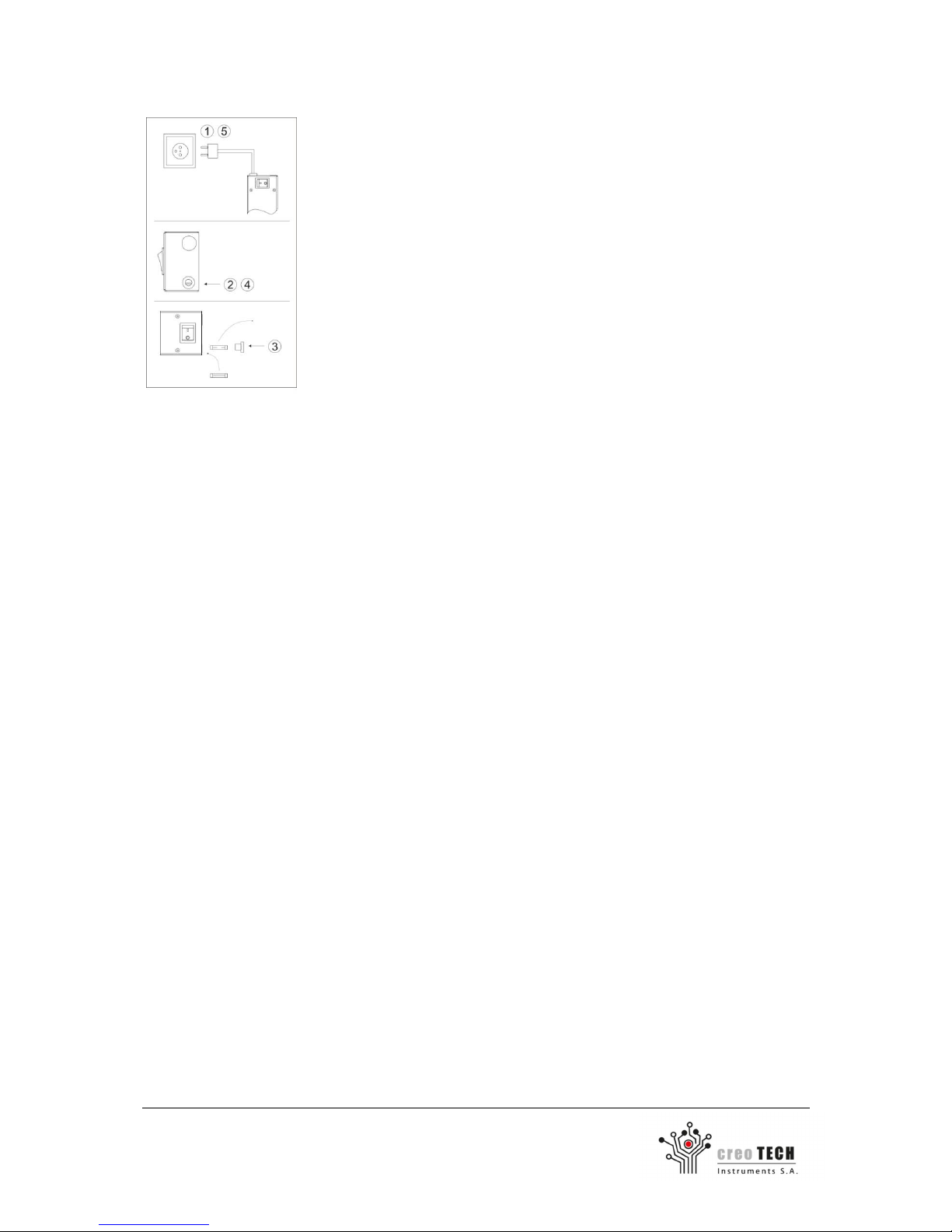
Replacing the blown fuse:
1) Unplug the power cord from the IP Power Strip.
2) Unscrew the fuse holder door and remove the fuse holder.
3) Remove and replace the blown fuse with the new fuse. Make sure
that the fuse is of the same type and current rating (Ø 5 mm x 20 mm, 16 A,
250 VAC, slow-blow fuse).
4) Install the fuse holder door.
5) Re-plug the power cord.
Replacing the real-time clock battery:
IP power strip equipped with a real time clock with battery backup. To replace the battery one
should reported to the manufacturer, battery shouldn't be replaced under any circumstances by
unauthorized person.
Page 30

30
Creotech Instruments S.A. tel. +48 22 233 10 27
ul. Gen. L. Okulickiego 7/9 e-mail: [email protected]
05-500 Piaseczno, Polska www.creotech.pl
4.3 Trouble-shooting
Issue Possible cause and solution
No reaction at all (e.g. no light
indicators)
No power supply is attached – check the main power cable and its
power source.
Only the main switch indicator
is on.
Replace the fuse. Make sure that the equipment connected to the
power strip outlets do not overload it.
It is not possible to access the
power strip through the web
page.
If the LINK LED diode (Ethernet) is off: check the Ethernet cable and
other network equipment (switch, router, etc.)
If the LINK LED diode (Ethernet) is on: check if the Ethernet
configuration is correct.
When connecting directly to the PC use CAT5 crossover cable.
When connecting through switch/router use regular CAT5 cable.
The configuration settings are
not saved.
After the changes in configuration settings are made it is necessary
to reboot the power strip in status tab.
Forgotten password or
username
Restore the factory settings and reconfigure the IP Power Strip by
executing the first start-up procedure or if you are a user - contact
with administrator.
Cannot access www page
during first start-up
Make sure a direct connection between PC and IP Power Strip is
made using CAT5 crossover patch cord.
Firmware upgrade
failed
Execute the procedure of restoring the factory software:
1. Turn off and on the power strip IP using the main switch
2. Wait for about two seconds until the ACT LED lights up
3. Press the reset button and hold it. When ACT LED starts to blink
- release the button
4. Wait two minutes. Do not turn the power off as this may
cause irreversible damage to the device. After two minutes,
turn off and on IP power strip, which will finish restoring the
factory software.
Page 31

31
Creotech Instruments S.A. tel. +48 22 233 10 27
ul. Gen. L. Okulickiego 7/9 e-mail: [email protected]
05-500 Piaseczno, Polska www.creotech.pl
CTI-PS6-MAN-v3.5 10/2015
Entire contents copyright Creotech Instruments S.A.
Reproduction in whole or in part without permission is prohibited.
Creotech Instruments S.A. logo are trademarks of Creotech Instruments S.A
Local distributor:
 Loading...